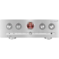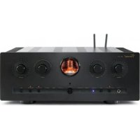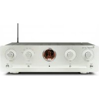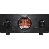
SV-200 - Receiver VINCENT - Free user manual and instructions
Find the device manual for free SV-200 VINCENT in PDF.


User questions about SV-200 VINCENT
0 question about this device. Answer the ones you know or ask your own.
Ask a new question about this device
Download the instructions for your Receiver in PDF format for free! Find your manual SV-200 - VINCENT and take your electronic device back in hand. On this page are published all the documents necessary for the use of your device. SV-200 by VINCENT.
USER MANUAL SV-200 VINCENT
Instructions for use
english

we thank you for the confidence you prove in purchasing our product. It will match your high demands towards sound and manufacturing quality. Though it is understandable that you want to plug and play this product instantaneously, we encourage you to read this manual carefully before installation.
It will help you in handling and operating this machine in your system and obtaining the best possible performance, even if it was installed by your dealer.
Please follow the security precautions, though some of those things may seem obvious.
In the appendix to this manual you will find a glossary explaining some established technical terms.
If there are open questions your audio specialist dealer will help you. He also represents your contact person in case of needed warranty service or repairs after the warranty period and is interested to hear from your experiences with Vincent products.
We wish you plenty of joy with your / our product,
your Vincent-Team
Cher client,
| Safety guidelines | 26 |
| Other instructions | 27 |
| Included in delivery | 28 |
| Description of the appliance | 29 |
| Remote control | 31 |
| Installation | 33 |
| Operating the appliance | 41 |
| Tips | 43 |
| Search for errors | 44 |
| Technical Specifications | 46 |
| Glossary | 47 |
english
7. DIGITAL IN: Optical/Coaxial
natural_image
Simple diagram showing a downward arrow pointing to a small object inside a container (no text or symbols)natural_image
Simple diagram of a mechanical component with an upward arrow, no text or symbols presentnatural_image
Diagram showing a cable connected to four circular components with directional arrows, no text or symbols present.This appliance was produced under strict quality controls. It complies with all established international safety standards. Nonetheless, the following instructions should be fully read and observed in order to prevent any hazard:

Do not open the appliance! Risk of electric shock! There are no parts in the appliance that require maintenance by the user

Maintenance/Alterations
All equipment that is connected to the domestic mains voltage can be dangerous to the user if not handled properly. Leave maintenance work to qualified professionals. The product is only permitted for connection to AC 230Volt/50Hz, for earthed sockets and use in enclosed areas. Altering the product or manipulating its serial number voids the warranty. After a fault, leave the appliance's fuse to be replaced only by a professional with one of the same kind.
Power Cable Connection
Always pull the plug and never the power cable if you want to disconnect the appliance from the mains power. Make sure when setting up the appliance that the power cable is not squashed, severely bent or damaged by sharp edges. Do not touch the power lead with wet or damp hands. Use the power cable supplied or another one from Vincent.


Switching Off
Switch the appliance off every time before you connect or remove other components or loudspeakers, disconnect or connect it to the mains power, leave it unused for a longer period or want to clean its outside. On all amplifiers and receivers, wait approx. 1 minute after this before disconnecting or reconnecting the cable.
Moisture/Heat/Vibration
Contact of electrically operated equipment with liquids, moisture, rain or water vapour is dangerous for such equipment and the user and must be avoi-
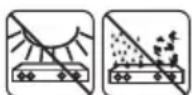
ded without fail. Take care that no liquids or objects get inside the appliance (ventilation slots etc.).
It must be disconnected from the mains power immediately and examined by a professional if this happens. Never expose the appliance to high temperatures direct sunshine or strong vibration.

Heat Build-up
Make sure that a gap of 5 cm remains around the appliance and that the surrounding air can circulate (do not install in enclosed cupboards). Vents must not be covered up.
Volume

The maximum tolerable volume is always reached well below the maximum possible setting on the amplifier. Be careful with the volume setting, therefore, in order to prevent damage to hearing. So that you do not expose yourself to high volumes unintentionally, always set to a low level before changing the input channel.

Cleaning
Pull out the power plug before cleaning the outside of the product. Whenever possible, use a soft, lint-free cloth that has been dampened. Do not use abrasives, solvents, thinners, flammable chemicals, polishes and other cleaning products that leave marks.
Batteries
Take note of the instructions for using batteries in the chapter "Remote Control".
OTHER INSTRUCTIONS
Setting up the appliance
How the system is set up has an effect on the sound quality. Therefore only place it on a suitable, stable surface. To make the most of your system's sound quality, we recommend placing the equipment on Vincent racks and not putting them on top of each other.
Old electronic equipment
This appliance is subject to the conditions set out in the European Directive 2002/96/EC. This is identified by the symbol of a crossed out waste bin on the appliance.
What this means for you as a consumer:
All old electrical and electronic equipment that is no longer used must be disposed of separately from domestic waste using places provided by the authorities. By doing so you can prevent damage to the environment and help to encourage manufacturers to produce more durable or reusable products. For further information about disposing your old appliance, please consult your local authority, waste disposal agency or the shop where you bought the product.
CE sign

This appliance complies with the current EU directives about attaining the CE mark and thus meets the requirements for electrical and electronic equipment (EMC regulations, regulations and regulations for low voltage equipment).
Declarations

This document is a product of Sintron Vertriebs GmbH, 76473 Iffezheim and may not be copied or distributed partly or in full without express, written consent.
Vincent is a registered trademark of Sintron Vertriebs GmbH, 76473 Iffezheim.
Vincent works continually to improve and develop its products. Therefore, the appearance and technical design of the appliance are subject to changes, as long as they are in the interest of progress.
The content of these instructions is for information purposes only. It can be changed at any time without prior notice and does not constitute any obligation on the part of the trademark's owner. The latter assumes no responsibility or liability for errors or inaccuracies, which may be included in these operating instructions.
Storage of the packaging
We strongly recommend that you keep the original packaging in case you need to transport the equipment again at a later date. Transport damages are mainly caused by improper packaging of the HiFi-devices. Because the original packaging fits the equipment accurately it will reduce the risk of damage if transport is necessary.
Explanation of the symbols

The lightening bolt tells you that dangerous voltages are present in the appliance, which can cause an electric shock.

This symbol brings your attention to particularly important information regarding operation and maintenance.

This symbol identifies useful information and advice about how to handle the appliance.
INCLUDED IN DELIVERY
Please check the contents of the packaging, which in addition to the appliance should contain the following accessories:
- 1 power cable
• 1 remote control VRC-8
• 1 coin cell CR2025 - this manual
DESCRIPTION OF THE APPLIANCE
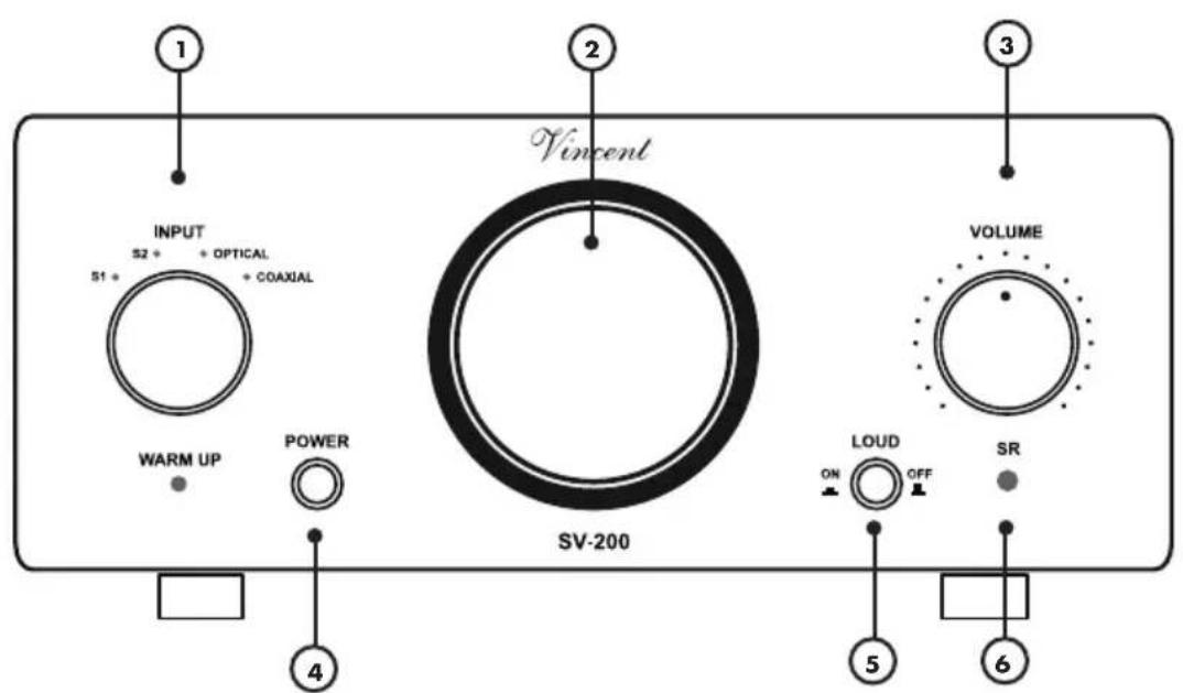
FRONT VIEW
text_image
1 2 3 Vicent INPUT S2 + OPTICAL 51 + COAXIAL WARM UP POWER 4 SV-200 VOLUME LOUD ON OFF SR 5 61. INPUT: Input Selector
This dial allows you to choose one of the six inputs.
2. Display window for the tube
3. VOLUME: Volume dial
This is the knob for the adjustment of the main volume level of the system.
4. POWER
This is the main power switch for turning on and off the device. The preamplifier is separated from the mains voltage when switched off and cannot be set into a standby state.
5. LOUD: Loudness function
This button activates and deactivates an audio signal correction that adapts the loudspeaker audio signal to the human auditory sensation in
6. Infrared remote control receiver
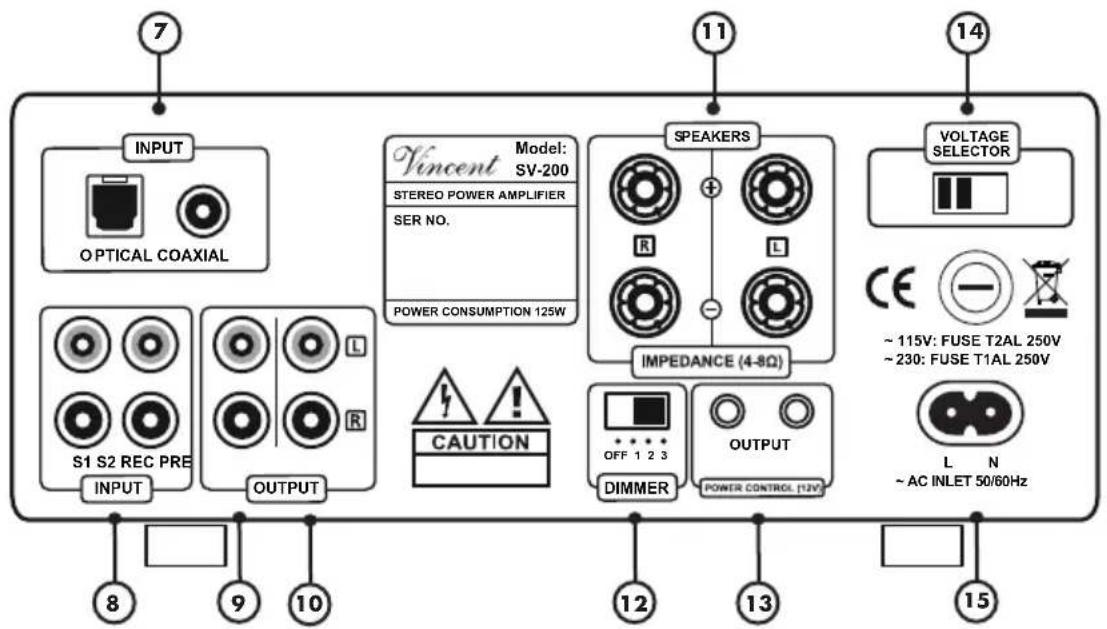
REAR VIEW
flowchart
graph TD
    A["7"] --> B["INPUT"]
    B --> C["OPTICAL COAXIAL"]
    D["11"] --> E["Vincent Model: SV-200"]
    E --> F["STEREO POWER AMPLIFIER"]
    E --> G["SER NO."]
    E --> H["POWER CONSUMPTION 125W"]
    I["14"] --> J["SPEAKERS"]
    J --> K["R"]
    J --> L["L"]
    J --> M["IMPEDANCE (4-8Ω)"]
    N["VOLTAGE SELECTOR"] --> O["CE ~ 115V: FUSE T2AL 250V"]
    N --> P["~ 230: FUSE T1AL 250V"]
    Q["12"] --> R["OUTPUT"]
    S["13"] --> T["POWER CONTROL (12V)"]
    U["15"] --> V["L N ~ AC INLET 50/60Hz"]
    W["8"] --> X["INPUT"]
    X --> Y["OUTPUT"]
    Z["9"] --> AA["S1 S2 REC PRE"]
    AA --> AB["INPUT"]
    AB --> AC["OUTPUT"]
7. DIGITAL IN: Optical/Coaxial
Connections for audio signals of source devices with digital sound such as, for example, DVD players. "Optical" for optical fibre connection and "Coaxial" for connection via coaxial cable.
8. INPUT: input connectors
Here you find two stereo RCA inputs for the source equipment with analogue stereo (line level) audio output.
9. REC OUT: recording output
If desired, you can connect a recording device like a CD recorder or a tape recorder to this output. The stereo signal of this output is identical to the output signal of the selected audio source at one of the pre-amplifier INPUTs. It is independent of the volume setting (3)(23), and the loudness setting (5).
10. PRE OUT: preamplifier outputs
With this pair of RCA connectors you can output the preamplified stereo audio signal of the currently selected source to power amplifier channels or an active subwoofer.
11. SPEAKERS: Speaker connectors
Output sockets with screw clamps for connection of one pair of loudspeakers. You can use loudspeaker cables with 4 mm banana connectors. Please refer to the precautions in the section "Installation" in case two pairs of loudspeakers are connected.
12. Dimmer for the tube illumination
The setting of this switch affects the brightness of the illumination of the tube display window (2).
13. POWER CONTROL (12V) OUTPUT
At these jack connectors the signals for the on/off control (Power Control, Trigger) are emitted.
14. Voltage Selector:
The voltage selector behind the pane allows switching the voltage from 230 V to 110 V.
Refer to safety instructions for further information (p. 36, "Switching the Voltage")
15. AC 220-240V:
Power Connector with Fuse holder
To establish the power supply, connect the plugs of the power cable to the device and to a suitable wall outlet. The small plastic housing holds the fuse. Refer to the security precautions.
REMOTE CONTROL
Point the front of the remote control directly at the front of the appliance, making sure there are no objects between the remote control and the appliance.
The distance between the remote control and the appliance should not be more than 7 m, as the reliability of the remote control is affected beyond this range.
Make sure that you do not point the remote control at an angle to the appliance, as beyond an angle of ±30^ to the centre axis the appliance may not respond as well to the remote control.
Change both batteries if the distance at which the remote control can be used effectively decreases.
BATTERIES
Using batteries
Handling batteries incorrectly can cause battery acid to escape or an explosion in extreme cases. The batteries must be correctly inserted taking note of the polarity, which is marked in the inside of the battery compartment.
In order to make full use of the batteries' life, do not mix new and used batteries. Make sure that you insert batteries of the same type.
Some batteries are rechargeable, others are not however. Take note of the precautions and instructions that are included on all batteries.
Remove the batteries if the remote control is not going to be used for a long time.
Under no circumstances must batteries be short-circuited, taken apart or heated up.
For environmental reasons, used batteries should be disposed of in accordance with local environmental regulations and not put with domestic waste.

Only use coin cell CR2025
Change/inserting the batteries:
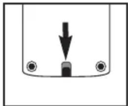
- Open the battery compartment of the remote control by pushing out the clip and pulling out the battery compartment.
natural_image
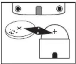
Simple diagram showing a downward arrow pointing to a small object inside a container (no text or symbols)- Remove the optionally used battery and correctly insert the new button cell, as schematically shown in the battery compartment.
text_image
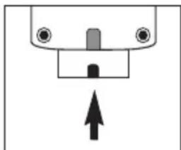
2.5 +- Close the battery compartment of the remote control.
natural_image
Simple diagram of a mechanical component with an upward arrow, no text or symbols presentBUTTONS OF THE REMOTE CONTROL

text_image
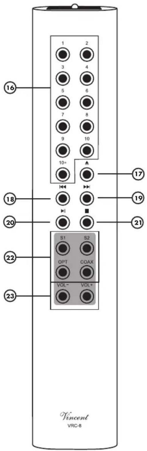
16 1 2 3 4 5 6 7 8 9 10 10+ 17 18 19 20 21 22 23 S1 S2 OPT COAX VOL-VOL+ Vincent VRC-816. Number buttons:
With these buttons you can select the tracks directly.
17. OPEN/CLOSE:
Button to open and close the disc tray.
18. BACK:
Press the button during the handover like in the order to get previous titles.
19. NEXT:
Press the button during playback in the order to get to the following titles.
20. PLAY/PAUSE:
With this button the CD playback can be started and briefly interrupted.
21. STOP:
This button stops a running CD playback
22. Input selector buttons:
Serve the selection of the input device that you want to hear.
23. VOL+ VOL-:
Volume keys. Change the system volume, VOL for louder, VOL- to decrease the volume.
INSTALLATION
Set up the cable links in a sequence as follows. Connect the power cable between device and power supply only after all other connections have been made.

DURING INSTALLATION PLEASE OBSERVE THE FOLLOWING ADVICE:

Protective caps
Prior to the first installation the protective plastic caps must be removed from all the connections used at the rear of the unit.
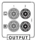
RCA connections
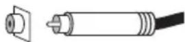
Mechanically identical RCA plugs are available for input and output connections. Make sure that you do not get these connections confused during
installation!
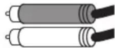
Make sure that you do not mix up the analogue inputs for right and left. The RCA plugs for these are mostly colour coded as follows: red for the right channel, black or white for the left channel.
Contacting the middle pin of the RCA plugs with the outer ring of the RCA chassis jack may lead to damages to the main amplifier if it is switched on! To avoid this hazard, connect or disconnect only in switched-off state and more than one minute after deactivating!
Speaker cable connections
The use of ready-made loudspeaker cables is recommended instead of connecting the cable's central wire (strand) directly to the terminals. Banana plugs or cable lugs ensure high security from short-circuits and damage to loudspeakers or amplifier.
Make sure that bare loudspeaker wires never come into contact with each other or with the metal on the back of the housing.
Make sure that the positive and negative loudspeaker wires are connected correctly. You will notice a reduced sound quality if the connections are the wrong way round.
Only use loudspeakers with a nominal impedance of at least 8 (if two pairs of loudspeakers are connected) and a nominal impedance of at least 4 (if one pair of loudspeakers is connected).
Cable connections
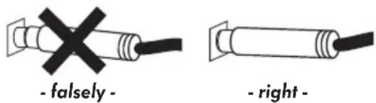
Make sure that all plugs fit tightly. Inadequate connections can cause noise interference, failures and malfunctions.
text_image
- falsely - - right -To make the most of the components' sound potential, only high quality loudspeakers and connecting cables, for example Vincent cables, should be used. Your local stockist will be glad to advise you about this.
CONNECTION OF THE SOURCE EQUIPMENT
Connect the outputs of the source appliances to the inputs (8) of this amplifier. The output sockets on the source equipment are usually indicated by "LINE OUT", "AUDIO OUT" or "FRONT OUT". You will find information about ways to connect source equipment in their operating manuals.

To use a record player you need a so-called phono preamplifier (also called an equaliser pre-amplifier), which is installed in the signal path between the record player and one of the high-level inputs. Some models of record player already include this preamplifier and can be connected directly. You will find further information in this appliance's operating manual.
The stereo sound of appliances that use output connectors other than RCA (DIN plugs, jack plugs) can often also be used with the aid of adaptors.
You can connect up to two devices with analogue RCA stereo high level output such as a CD player in order to provide the audio signals of your input sources to the system. All six inputs represent electrically equivalent standard high level inputs with RCA connection. They have an identical function and differ only in name.

flowchart
graph LR
    A["SV-200 Device"] --> B["RCA-Connection"]
    B --> C["CD-Player, Tuner, DVD-Player, etc."]
    A --> D["INPUT"]
    B --> E["S1 S2"]
    E --> F["LINE OUT"]
CONNECTION OF A RECORDING DEVICE
If you want, you can use the RCA sockets "REC OUT" (9) on the back of the appliance to connect an analogue stereo recording device (e.g. CD recorder, cassette recorder etc.) or another appliance that is intended for receiving the unchanged, fixed stereo output level (line level) from the signal source selected on the amplifier at any given time. The output level is independent of the Volume setting and the Loudness.

flowchart
graph LR
    A["SV-200 Device"] --> B["REC OUT"]
    B --> C["RCA connection"]
    C --> D["LINE IN"]
    D --> E["Recording device, e.g. tape recorder"]
Connect this signal output to the signal input ("LINE IN", "TAPE IN" or "REC IN") on the recording appliance using RCA cables. Please note that some recording equipment can have a slightly detrimental effect on the audio signal quality. Some recording devices have rather low input impedance, which can slightly alter the input signal voltage. For maximal music enjoyment we recommend that you connect to the "REC" terminal only for as long as the recording is actually being made.
CONNECTION OF TWO ADDITIONAL MAIN AMPLIFIER CHANNELS
You only need the "PRE OUT" sockets (10) if you want to use a separate stereo amplifier or two mono amplifiers to supply two additional loudspeakers. This makes sense if you intend to use two more loudspeakers for stereo music playback, for example in a separate zone (another room of your home). These loudspeakers are then connected to the speaker outputs of the additional amplifier(s). The amplifier output connections "PRE OUT" (10) must be connected with the input connectors of the main amplifier, in most cases labelled "INPUT", "POWER AMP IN" or "MAIN INPUT".

flowchart
graph LR
    A["SV-200"] --> B["RCA connection"]
    B --> C["Stereo main amplifier"]
    A --> D["PRE OUT"]
    D --> E["INPUT"]
Instead of the stereo main amplifier shown here you can alternatively use two mono main amplifiers.
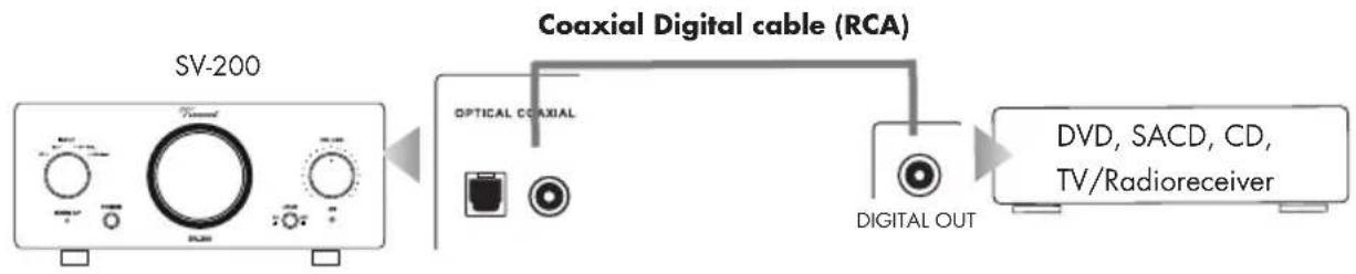
CONNECTION OF SOURCE DEVICES OVER OPTICAL IN AND COAXIAL IN
The integrated D/A converter makes it possible to receive also digital audio signals via an optical and/or coaxial cable and to transmit them analogously to the amplifier. Here, the "Optical IN" and "Coaxial IN" (7) connections serve as input.
Digital audio source with optical signal connection

flowchart
graph LR
    A["SV-200"] --> B["Optical digital cable"]
    B --> C["DVD, SACD, CD, TV/Radioreceiver"]
    B --> D["OPTICAL COAXIAL"]
    D --> E["DIGITAL INPUT"]
    B --> F["OPTICAL DIGITAL OUT"]
Digital audio source with coaxial signal connection
flowchart
graph LR
    A["SV-200 Device"] --> B["Coaxial Digital cable (RCA)"]
    B --> C["DVD, SACD, CD, TV/Radioreceiver"]
    B --> D["DIGITAL OUT"]
    style A fill:#f9f,stroke:#333
    style B fill:#ccf,stroke:#333
    style C fill:#cfc,stroke:#333
    style D fill:#fcc,stroke:#333
SWITCHING THE VOLTAGE
This device is equipped with a switch (14) that can be used to change the country-specific voltage from 230 V to 110 V.

Please never actuate the switch during operation! The voltage must only be switched by a technician, since the device fuse must also be replaced after actuation of the switch! Information about the device fuse can be found on the back of the device.
Unauthorised actuation of the switch will void any warranty claim!
CONNECTIONS FOR THE STANDBY CONTROL (POWER CONTROL)
Many AV-Systems consist of a multitude of individual components. To avoid the necessity of switching them on and off before and after every use, many manufacturers have equipped their devices with what is known as "POWER CONTROL" circuit or "TRIGGER". This kind of remote-controlled standby circuit is used primarily for preamplifier and power amplifiers. Particularly for preamplifiers and main amplifiers this kind of remote standby control is utilized, as power amplifiers are often placed far from other devices near the speakers. To employ these functions, direct or indirect cable connections must be made between the preamplifier (or integrated amplifier) and all the devices which support this function. The "POWER CONTROL" function operates in such a way that each switching on or off of one device in the system (usually the preamplifier) automatically brings about the switching on or off of all the connected devices which support this function. Please keep in mind that all devices which respond to the power control are not disconnected from the mains network when switched off. They are set to a standby state instead. For connecting cables, two-core cables with 3.5 mm jack plugs (mono) are used. For each connection between two devices one of those cables is needed.
If you don't wish to use this function or if the other components do not support it, all you have to do is leave out these cable connections.
The SV-200 is equipped with two output connectors for the power control. Here, the switching signal generated by the amplifier is available for other components of the system. Two HiFi components that are able to react to the power control signal can be connected directly to the amplifier's power control outputs (13). If more than two devices, which can be controlled, are to be connected, then it is necessary to make the power control connection between the amplifier and these further devices through the outputs of the two devices which are connected directly. For that reason, every HiFi component that accepts power control signals is also equipped with a power control output. Thus, in theory it is possible to provide an infinite number of HiFi components with the power control signal. This approach, to loop a signal through a chain of components, is commonly referred to as "daisy chaining".
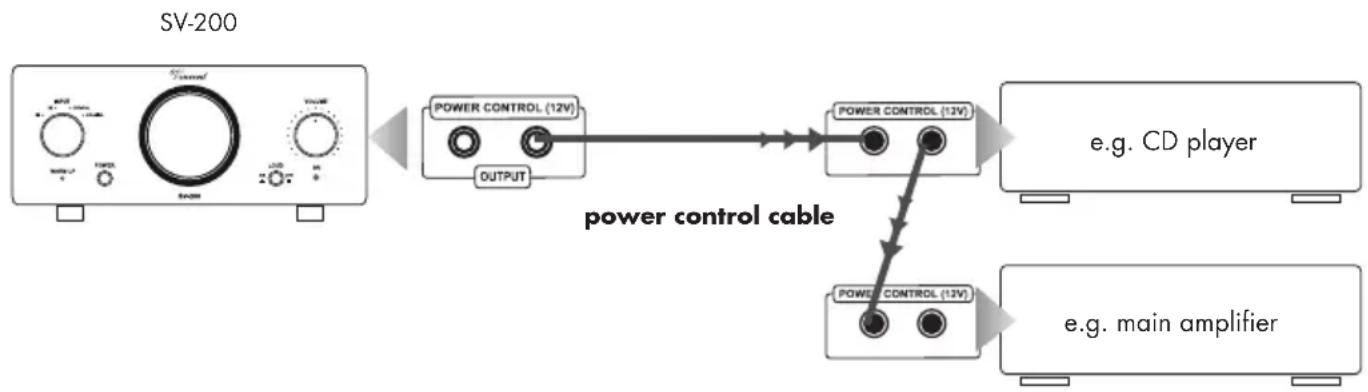
flowchart
graph LR
    A["SV-200 Device"] --> B["power control cable"]
    B --> C["Power CONTROL (12V)"]
    B --> D["OUTPUT"]
    C --> E["Power CONTROL (13V)"]
    D --> F["Power CONTROL (13V)"]
    E --> G["e.g. CD player"]
    F --> H["e.g. main amplifier"]
CONNECTIONS FOR THE STANDBY CONTROL (POWER CONTROL)

Many devices which can be controlled by a switching signal (not preamplifiers or integrated amplifiers), have two terminals which do not differentiate between input and output. In this case either of the two can be selected.
"POWER CONTROL" sockets of preamplifiers or integrated amplifiers must not be interconnected! All receiving devices must not be connected to more than one preamplifier or integrated amplifier (directly or indirectly)!
Check whether the wall socket provides the appropriate mains power, which is the case if it is supplied with 230 V AC 50 Hz. Push the plug on the power cable supplied firmly into the power socket (15) on the back of the appliance. Plug the other end of the power cable into a mains socket.
CONNECTION OF THE LOUDSPEAKERS
A single pair of loudspeakers can be connected to the amplifier SV-200. Both stereo outputs are identically provided with the signal of the currently selected input. For each loudspeaker you will find two connector screws (positive + und negative -) at the amplifier's backside. One side of the speaker cable must be attached here. Each pair of screws has a label "R" or "L" nearby to clarify to which stereo channel it belongs. At the loudspeaker connection terminal there are similar connector screws or connectors. There, the polarity of each screw (+ or -) can be identified as well and the other side of the speaker cable associated with this speaker must be attached. Make sure only connector screws of the same polarity will be connected by each speaker cable wire: a knob marked "+" in the amplifier's terminal must be connected with a speaker's connector screw marked "+" as well.
Our sketch shows all connections necessary for one pair of speakers.
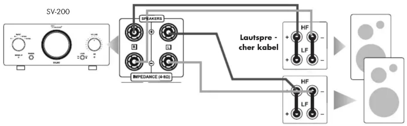
flowchart
graph LR
    A["SV-200 Device"] --> B["SPEAKERS"]
    B --> C["Lautspre-cher kabel"]
    C --> D["Output Display"]
    B --> E["IMPEDANCE (4-8Ω)"]
    E --> C
    style A fill:#f9f,stroke:#333
    style D fill:#bbf,stroke:#333
Right and left loudspeaker
If every speaker is connected in a conventional way (a two core speaker cable for each loudspeaker) and you own loudspeakers that are equipped with Bi-Wiring terminals (four connector screws) you have to make sure that the metal brackets (contact pieces consisting of small metal plates or short pieces of cable which are supplied with the speakers) are applied to the terminal and that each one connects the two knobs of the same polarity (e.g. both connectors marked "+" ). The connector screw labelled "+" and "R" at the amplifier's backside must be connected to one of the bridged, labelled "+" connectors of the loudspeaker assigned to the right stereo channel. Accordingly, the connector screw labelled "-" and "R" at the amplifier's backside must be connected to one of the bridged, labelled "-" connectors of the loudspeaker assigned to the right stereo channel. Connect the left side loudspeaker in the corresponding way.
CONNECTION OF THE LOUDSPEAKERS
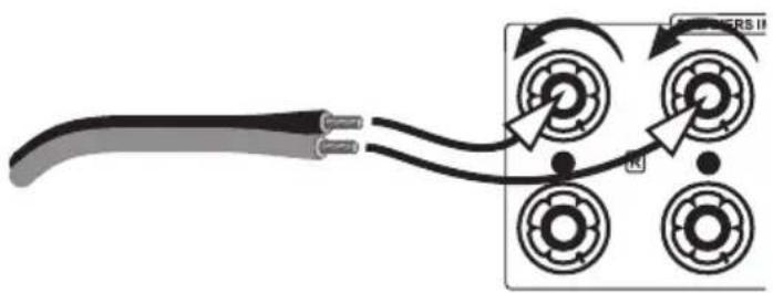
If you are using ready made loudspeaker cables with 4 mm banana plugs, all you need to do is connect the two plugs on each loudspeaker cable end to the two associated speaker connectors. Turn the connector screws clockwise to fasten them.
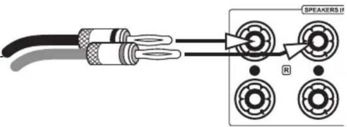
text_image
SPEAKERS II RIf you want to use speaker cables equipped with spade lug connectors, every connector screw must be opened by turning counter clockwise. After
that, the lug must be moved under the screw head. Then, turn the screw clockwise to fasten the lug to the connector. To avoid damages to the amplifier, make sure the connection is tight and no bare metal from the cable lug connector makes contact with the rear panel or with another terminal.
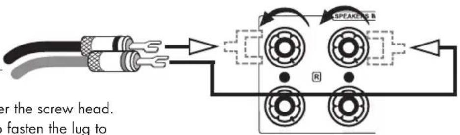
text_image
er the screw head. fasten the lug to SPEAKERS RIf no connector is to be used, remove approximately 1 cm length of insulation from each end of the speaker wire. Twist the braid in order to avoid short circuits. Turn the fastener on the loudspeaker terminal counter clockwise to loosen it and introduce the bare wire end into the exposed connector hole. Then turn the fastener clockwise so that the wire is firmly clamped. Make sure the connection is pretty tight.
natural_image
Diagram showing a cable connected to four circular components with directional arrows, no text or symbols present.OPERATING THE APPLIANCE
| Operation Button(s) Description | ||
| Switch on and off POWER (4) | The preamplifier is switched on and off using this button at the front panel. It has no standby option. When switched off the device is internally separated from the AC power. As a precaution, after switching on, the volume setting (3)(23) of the preamplifier should be reduced. | |
| Select an input | INPUT (1)Input selection keys (22) | At the front panel: If you turn the dial “INPUT”, you select one of the devices connected to the inputs on the back of the SV-200 (8) for playback. Using the remote control: A short touch on the button for the desired input channel (e.g. “S1”) changes to the playback of the audio source connected there.The LED associated to the selected input channel will be illuminated at the front of the appliance. Before switching over the input channel, the volume (3)(23) should be turned down as a precaution! |
| Change the volume | VOLUME (3)VOLUME▲/▼ (23) | At the front panel: Turn the knob “VOLUME” clockwise to turn up the volume and counter-clockwise to turn it down.Using the remote control: Press and hold the button “VOLUME ▲” to raise its value. Use “VOLUME ▼” to lower the volume level.The volume setting controls the speakers and the signal level at the “PRE OUT (10) but does never influence the signal at the output “REC OUT” (9). |
OPERATING THE APPLIANCE
| Operation Button(s) Description | ||
| Switch on/off the audio signal correction for low volume on and off | LOUD (5) | This function is operated from the front panel. It is a feature of audio amplifiers that permits the user to strengthen low and high frequencies compared with middle frequencies at the touch of a button. It thereby corrects the impression of volume at low volume. In an audio system, when the volume is small, low and high frequency ranges are insufficient because of the characteristic of human auditory sensation. This function should only be used at low volume. It has no effect on the signal of the recording output “REC OUT” (9). |
TIPS
Burn in/ Warm up
Your audio components need a certain time period until they reach maximum performance. The duration of this "warm up" time is very different for the various elements of your audio system. Higher and homogeneous sound quality is achieved while keeping the device switched on.
Your audio specialist dealer has enough experience to give you more information.
Net frequency noise
Some audio source devices may in combination with the amplifier cause a humming noise at power line frequency audible from your speakers. Usually, its volume varies with the volume setting of the amplifier. This is no sign of a defect or fault of your audio products but has to be eliminated. Generally, every wall-powered device connected to the ground wire of the power plug can cause this problem when connected to the amplifier.
Experience shows that this problem is mainly caused by antenna-connected components (as TV-sets or Tuners), personal computers, electrostatic loudspeakers, subwoofers, record players or headphone amplifiers that are connected to the audio inputs of the amplifier. Another possible reason for humming noise is electromagnetic interference of other components' power supplies with pick-up-systems of record players (change the place of the record player for a test).
In most electric devices the ground potentials of all signals are connected to each other at one central point, where they have one common connection. If the device uses the protective conductor of the wall outlet, the corresponding wire of the line cord is connected intractably to the metal housing of the device. This is the mostly the point where the central grounding point is attached to. By doing this the housing is able to shield all signals from external radiated noise. Some main amplifiers are equipped with a "Ground Lift"-switch. If it is activated, ground potential of the chassis and the protective ground wire are being separated from the central signal ground point. The protective ground wire keeps its function. Sometimes this helps prevent noise caused by errors in grounding.
If the problem occurs and cannot be solved by yourself your audio specialist dealer will help you.
SEARCH FOR ERRORS
| Symptom | Possible Cause | Countermeasure |
| Unit does not work after pressing the power button | Mains cable is not connected to a suitable mains wall outlet.Mains cable has not been firmly inserted into wall power socket and the device's socket. Otherwise it may be defective.Unit fuse or unit is defective. | Connect to a functioning socket using a suitable mains voltage.Check the power cable. If necessary, exchange it with a suitable mains cable and push its plug firmly into wall socket and the device's power connector.Contact your dealer. |
| No sound on both channels although the unit is ready for use | The currently selected audio source (1)(22) is giving no signal.One of the audio settings of a connected DVD player (analogue/digital) has not been correctly selected.The output of the source device is not connected or is wrongly connected e.g. not connected to the selected input channel terminal of the amplifier.Wrong input channel has been selected at the amplifier.The Volume setting is set too lowThe speaker cables are not properly connected to the amplifier's terminals or are defective. | Switch on the source unit and begin play-back.Correct the settings in the player's setup.Correct the connection.Set the amplifier to the input that your desired source is connected to (1)(22).Carefully increase the volume (3)(23).Check and tighten the speaker cables at the amplifier and at the speakers. |
| No audio playback on one channel | The source equipment is giving signal on only one channel.One of the signal cables between audio source and amplifier inputs has not yet been plugged in or is defective.One of the speaker cables is not correctly connected or is defective. | Check the audio source. You can try to use it at a different amplifier for a test.Check the cable connections, tighten them if necessary.Check and refasten the speaker cables at the speaker terminal of the amplifier and at the speaker's connectors. The cables coming from both the speakers of a speaker pair must not be connected to different terminal sets (e.g. one A and one B) on the back of the amplifier. |
SEARCH FOR ERRORS
| Symptom Possible Cause Countermeasure | ||
| Poor sound quality | The cable connections are not tight, the connectors are dirty or a cable is defective.A record player has been connected to a line level input without using a phono preamplifier. | Check the cables and cable connections.Interconnect a phono preamplifier. |
| The remote control cannot perform any functions | No batteries inserted in the remote control, batteries are not inserted correctly or are depleted.The line-of-sight between the remote control and the unit is obstructed, the range was exceeded or the hand unit was operated from a position too far to one side.The unit is not switched on. | Check and replace the batteries if necessary.Try to point the remote control at the front of the unit only when the sight-line is clear, within a 7-metre distance and, if possible, facing the unit.Switch on the unit. |
| Humming low frequency noise is audible, even as no audio source is playing back | See section "Net frequency noise" in the chapter "Tips". | |
TECHNICAL SPECIFICATIONS
Frequency response:
Nominal Output Power at 8 Ω:
Nominal Output Power at 4 Ω:
Input sensitivity:
Total Harmonic Distortion:
Signal to Noise Ratio:
Input Impedance:
AC power connection type:
Inputs:
Outputs:
Dimensions (W x H x D):
Weight:
Colour:
Tubes:
20 Hz - 20 kHz ±0,5 dB
2 × 25 W (RMS)
2 × 35 W (RMS)
220 mV
< 0.1 % (1 kHz, 1 W)
72 dB
47 kΩ
230 V/50 Hz
2 x Cinch stereo, 1x Coaxial IN, 1x Optical IN
1 x REC Out RCA, 1x PRE Out RCA,
2 x Power Control (3.5 mm jack socket),
2 × 2 speaker clamps
210 × 95 × 320 mm
5 kg
black / silver
2 × 6N1
GLOSSARY
Audio Sources/Source devices
These are the components of your HiFi system and all other appliances, whose sound you want to hear over the system and are thus connected to the pre-amplifier, amplifier or receiver. This includes CD players, DVD players, tuners (radios), cassette players, DAT recorders, personal computers, record players, portable audio devices and many more.
dB Level
This is a way of describing any physical quantity; it is a common measurement for signal voltages and the volume. It is given in decibels (dB). Alter na ting signal voltages below 1V (RMS) are described as "line level" voltages, which are suitable as music signals for amplifier inputs. Inputs on amplifiers (mostly represented by RCA sockets), which are designed for signals on the CD player, tape re corder, DVD player etc. are also referred to as "line level inputs". Those signal inputs must not be confused with inputs that accept preamplified signals.
Dynamic
The volume difference between the quietest and the loudest sounds possible in audio signals (with -out distortion or transition to noise). Dolby-Digital and DTS soundtracks allow very high dynamics and produce excellent cinema-like effects.
Input sensitivity
Term for the smallest average (RMS) input voltage which causes the maximum output power at the maximum volume setting on the amplifier.
Examples: 100 mV to 500 mV (Millivolts) on line level inputs, 2 mV to 5 mV on the phono MM input or 0.1 mV to 0.5 mV on the phono MC input.
RCA
RCA is the American name for a type of coaxial connectors and sockets, originally the abbreviation for "Radio Corporation of America", the name of a United States company. Both the plug and cable consist of a rod-shaped inner lead and a cylindrical-shaped outer lead. This enables a mono audio signal or a video signal to be transmitted. Compared to the XLR plug connector, this type of connection is also called "unbalanced signal connection".
CONSIGNES DE SECURITE
7. Digital IN Optical/Coaxial
natural_image
Simple diagram showing a downward arrow pointing to a central object with two circular base points (no text or symbols)text_image
Diagram showing a battery with an arrow pointing to a circular component and a plus sign, likely indicating a positive charge or polarity.natural_image
Simple diagram of a mechanical component with an upward arrow, no text or symbols presentTOUCHES DE LA TELECOMMANDE
text_image
16 1 2 3 4 5 6 7 8 9 10 10+ 17 18 19 20 21 22 23 S1 S2 OPT COAX VOL-V VOL+ Vincent VRC-Bflowchart
graph LR
    A["SV-200 Device"] --> B["Cable coaxial (RCA)"]
    B --> C["DIGITAL OUT"]
    C --> D["DVD, SACD, CD, TV/Radio receiver"]
    B --> E["OPTICAL COAXIAL"]
    E --> F["DIGITAL INPUT"]
COMMUTATION DE TENSION
natural_image
Pure electrical circuit lines without any symbolsUTILISATION DE L'APPAREIL
Please keep the receipt, store it together with this manual. The receipt is your proof for the beginning of the warranty period. Note the serial number in the following box, you can read it from the rear side of the device.