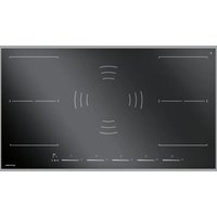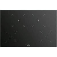
1PKC80N - Cooker BARAZZA - Free user manual and instructions
Find the device manual for free 1PKC80N BARAZZA in PDF.


User questions about 1PKC80N BARAZZA
0 question about this device. Answer the ones you know or ask your own.
Ask a new question about this device
Download the instructions for your Cooker in PDF format for free! Find your manual 1PKC80N - BARAZZA and take your electronic device back in hand. On this page are published all the documents necessary for the use of your device. 1PKC80N by BARAZZA.
USER MANUAL 1PKC80N BARAZZA
EN Use and installation manual
text_image
Technical diagram showing a bent pipe with an arrow indicating direction, alongside a detailed close-up of a 2 mm measurement scale.Fig. 3
text_image
20 mm min. 50 mm 54 mmFig. 4
text_image
Fig. 4Fig. 5
text_image
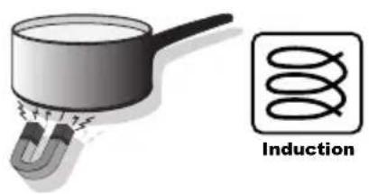
InductionA
text_image
Diagram showing six cooking methods with crossed cooking panes and pots, likely illustrating heating or cooking process.B

natural_image
Three schematic diagrams showing cross-sectional views of a container with handles, no text or symbols present.Fig. 6/A
1 PIDC60N

text_image
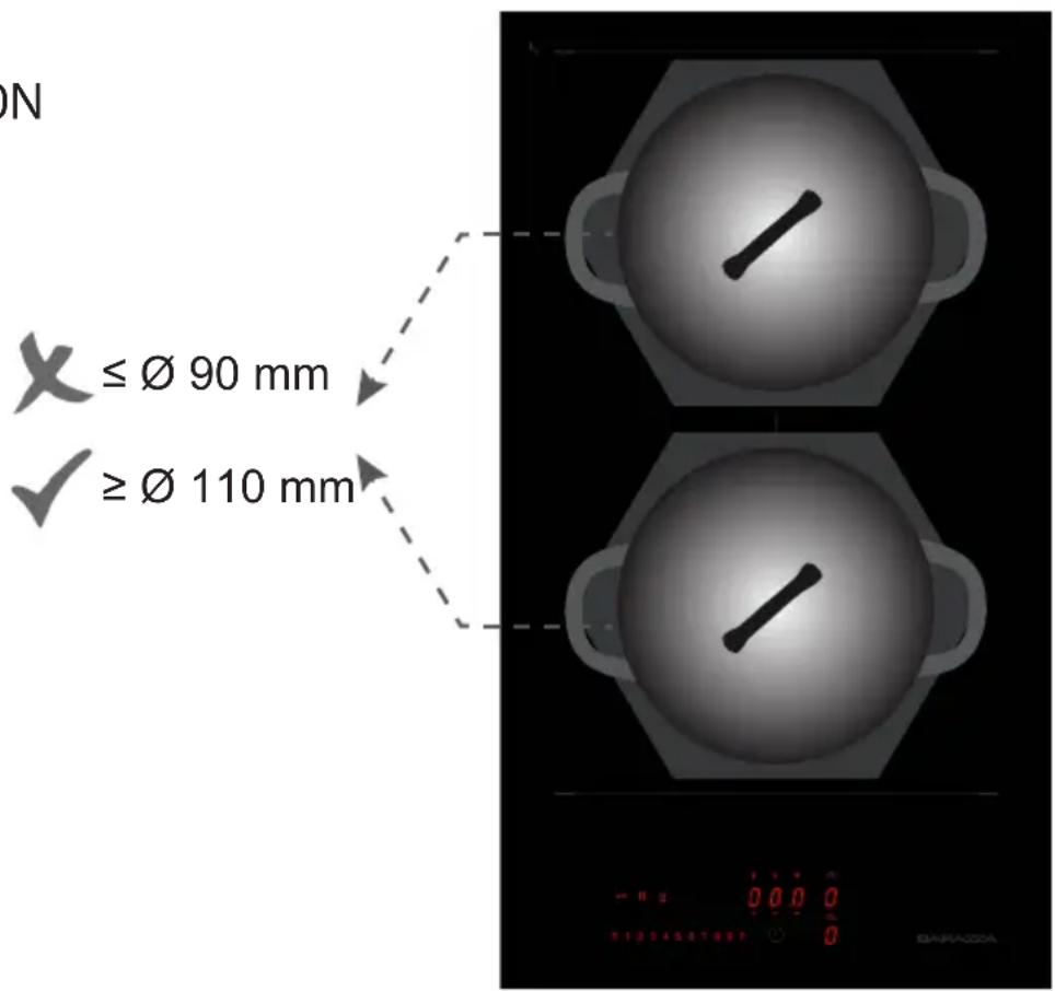
X ≤ Ø 90 mm ✓ ≥ Ø 110 mm X ≤ Ø 90 mm ✓ ≥ Ø 110 mm X ≤ Ø 190 mm ✓ ≥ Ø 230 mm X ≤ Ø 190 mm ✓ ≥ Ø 230 mmFig. 6/B
1PIDC30N
text_image
ON X ≤ Ø 90 mm ≥ Ø 110 mm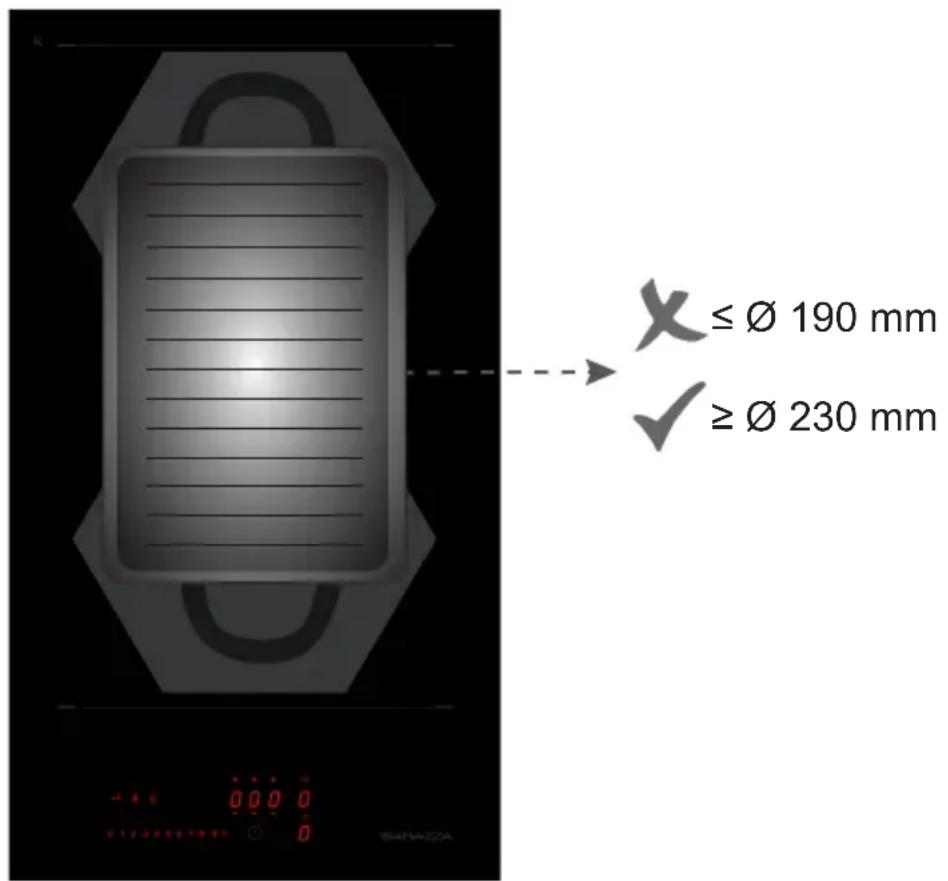
text_image
≤ Ø 190 mm ≥ Ø 230 mmFig. 6/C
1 PIDC80N
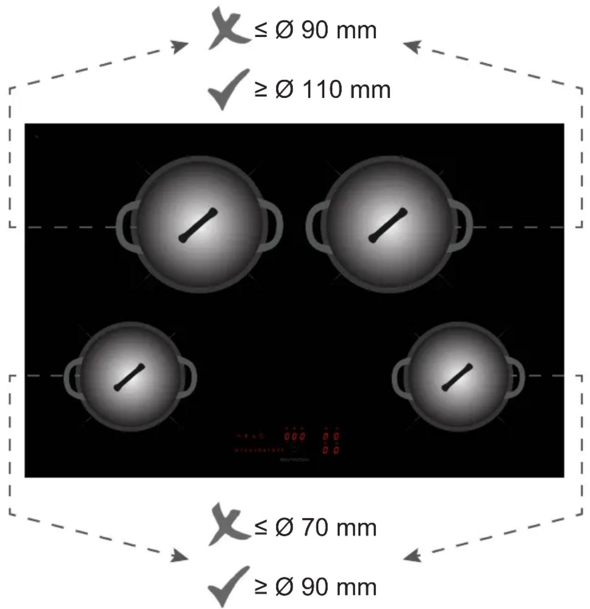
text_image
X ≤ Ø 90 mm ✓ ≥ Ø 110 mm X ≤ Ø 70 mm ✓ ≥ Ø 90 mmFig. 6/D
1PIDC90N
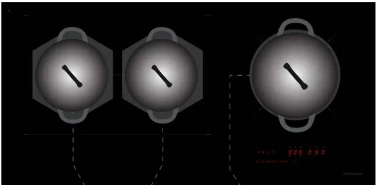
natural_image
Three identical circular diagrams with a diagonal line inside, connected by dashed lines to a digital display showing red '0.00 0.00' (no text or symbols on diagrams)≤ 90 mm
X ≤ ∅ 90 mm
√ ≥ ∅ 110 mm
√ ≥ ∅ 110 mm
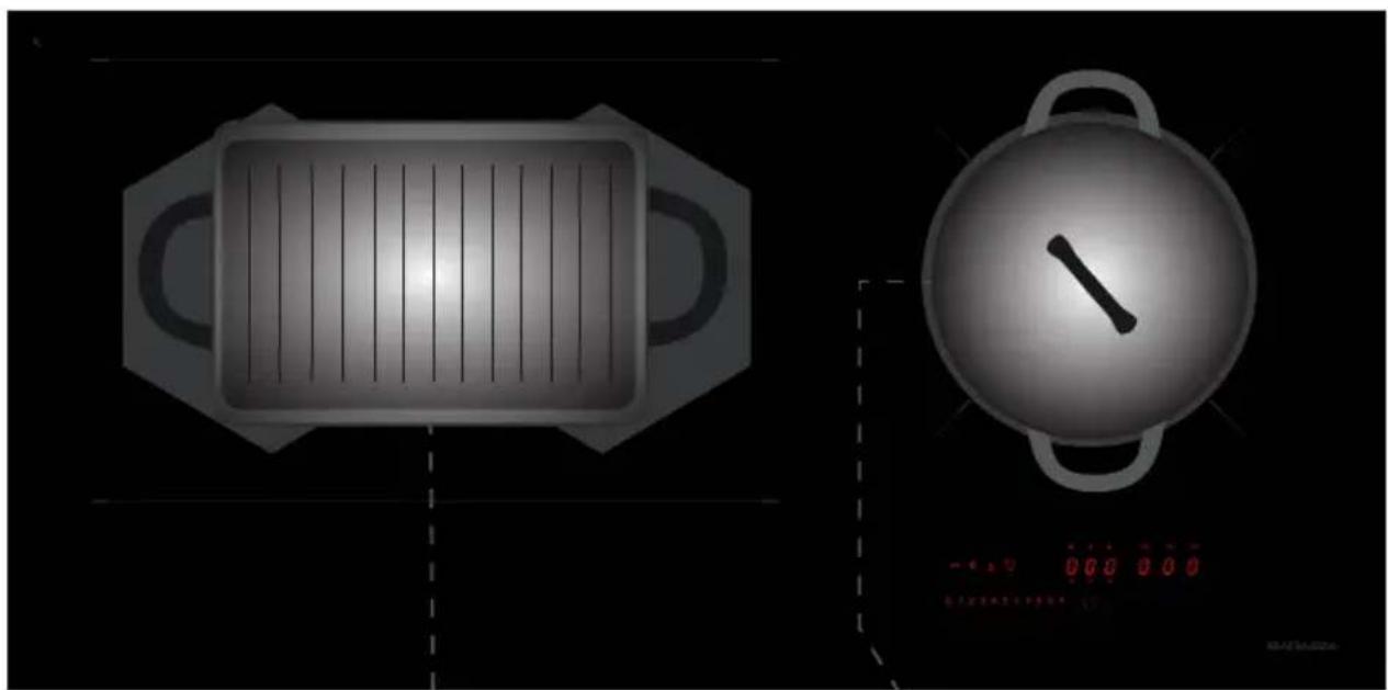
natural_image
Two technical illustrations: a rectangular stove with vertical slats and a circular pot with a diagonal handle, both on black background (no text or symbols)X ≤ ∅ 190 mm
X ≤ ∅ 90 mm
√ ≥ ∅ 230 mm
√ ≥ ∅ 110 mm
Fig. 6/E
1 PIDC120N
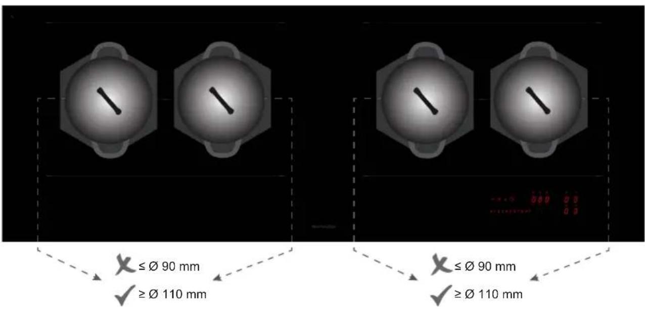
text_image
≤Ø 90 mm ≥Ø 110 mm ≤Ø 90 mm ≥Ø 110 mm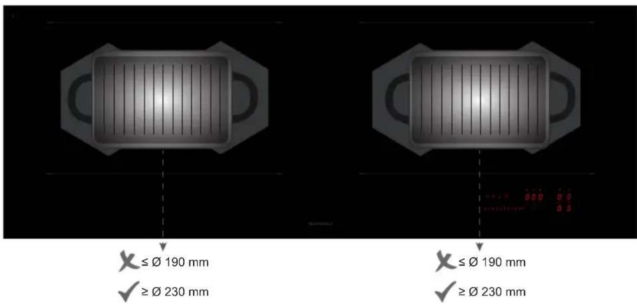
text_image
X ≤ Ø 190 mm ✓ ≥ Ø 230 mm X ≤ Ø 190 mm ✓ ≥ Ø 230 mmFig. 7/A
1 PIDC30N
text_image
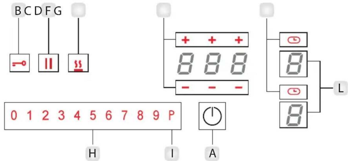
BCDFG - || ## 0 1 2 3 4 5 6 7 8 9 P H I A + + 8 8 8 - - - 8 8 - L 8 8EN
A_Power on Key
B_Key lock
C_Pause and Recall
D_Keep warm key
F_Timer level increment / Timer level decrement
G Timer On
H_Power level setting display
I Booster
L_Cooking zone display
IT
text_image
N L2 L1 35 24 1 2Ph+N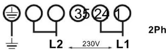
text_image
L2 ③5 ②4 1 230V L1 2Ph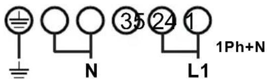
text_image
± N ③5 ②4 1 L1 1Ph+N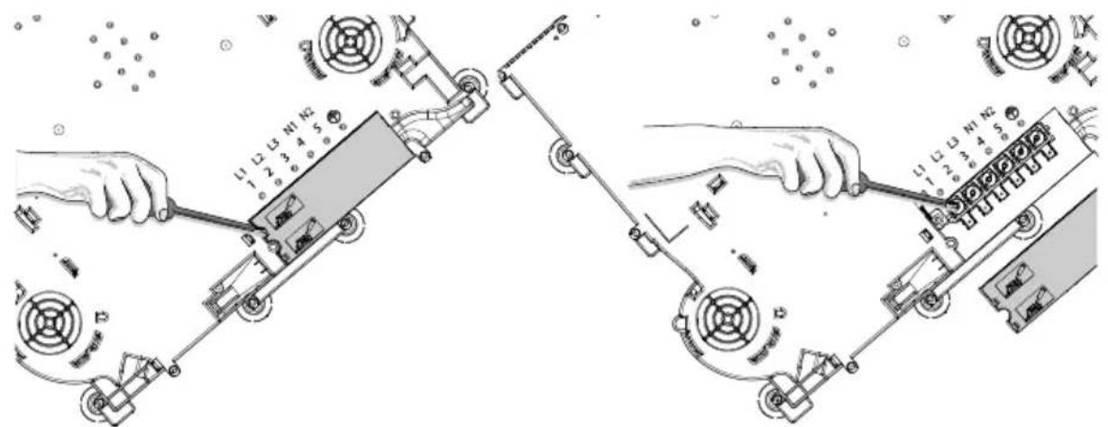
text_image
Technical diagram showing two mechanical assembly steps with labeled components and directional arrows indicating motion or movement.Fig. 9
natural_image
Illustration of a hand using a power tool to clean or brush on a dark surface (no text or symbols)EN | Induction Hob | User instructions
GENERAL INFORMATION
Carefully read this use and maintenance manual, where important information about installation, use and maintenance safety is provided. Keep this manual for future reference. Any installation operation (electric connections) shall be performed by specialized personnel, in compliance with all standards and regulations in force.
SAFETY WARNING
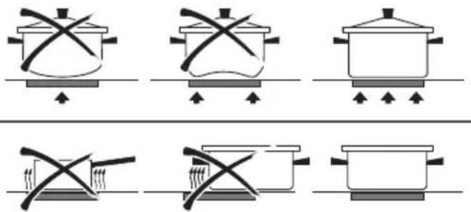
The use of flat-bottomed pots, with a diameter equal to or slightly bigger than the heated area, is recommended. (Fig.6). Do not use pots that have a rough base, in order to prevent the hob thermal surface from being scratched. This appliance is not intended for use by children or in-firm people without supervision.
IMPORTANT
- Avoid the overflow of liquids by reducing the heat supply when boiling or warming liquids.
- Do not leave any heating element switched on, if there are no pots, or if the pots are empty.
- Once cooking is completed, turn the concerned heating element off, by using the control shown below.
- This appliance is not intended for use by people (children included) with limited physical, sensorial or mental abilities,
or lacking of experience and knowledge, unless they are supervised or well instructed about the use of the appliance, by a person who is responsible for their safety.
- Children should be supervised to assure that they do not play with the appliance.
- If the hob surface is cracked, turn the appliance off and disconnect it from the electric network, so as to avoid the possibility of electric shock.
INSTALLATION INSTRUCTIONS
These installation instructions are intended for a specialized installer and are meant as guidelines for the hob installation, adjustment and maintenance, in compliance with any regulations and standards in force. If a built-in oven or any other appliance generating heat is to be mounted directly under the vitro-ceramic hob, IT IS NECESSARY THAT SUCH AN APPLIANCE (the oven) AND THE VITRO-CERAMIC HOB ARE PROPERLY INSULATED. Failure to comply with this precaution might result in the incorrect operation of the TOUCH CONTROL system.
- Positioning:
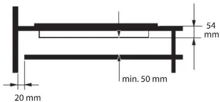
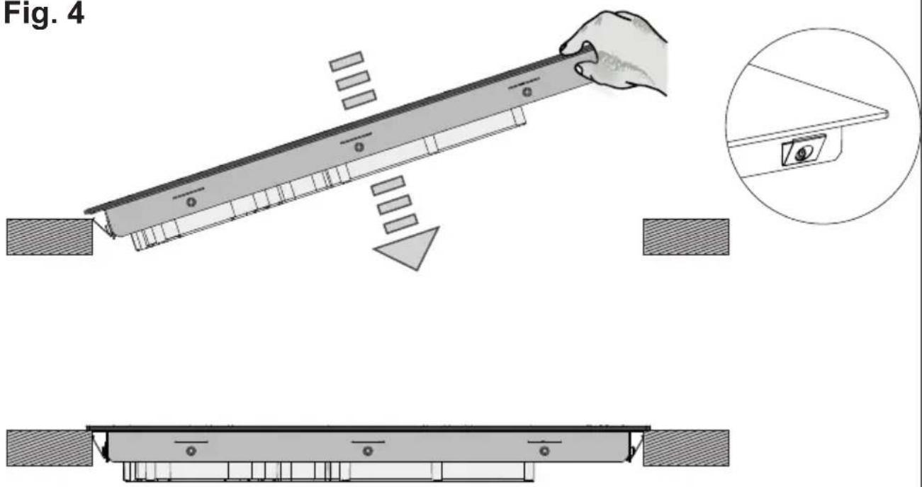
This household appliance has been designed for built-in installation onto a worktop, as shown in the figure (Fig. 1- Cut dimensions). Use sealing material along the whole perimeter (Fig.2). This operation is necessary in order to prevent any liquid from entering inside the hob, being that the flatness of the top, the glass and their coupling cannot be assured. Gently push the appliance into the built-in hole (Fig.4). If, after installation, the lower part of the appliance is accessible from the lower part of the cabinet, it will be necessary to mount a spacing panel at the distances given (Fig.3).
• Electric connections (Fig.8):
- The installation of this appliance and the connection to the electrical network should be entrusted only to an electrician perfectly to the fact of the normative regulations and which respects them scrupulously.
- Protection against the parts under tension must be ensured after the building-in.
- The data of connection necessary are on the stickers place on the hob casing near the connection box.
- The connection to the main must be made using an earthed plug or via an omnipolar circuit breaking device with a contact opening of at least 3 mm.
- The electrical circuit must be separated from the network by adapted devices, for example: circuit breakers, fuses or contactors.
- If the appliance is not fitted with an accessible plug, disconnecting means must be incorporated in the fixed installation, in accordance with the installation regulations.
- The inlet hose must be positioned so that it does not touch any of the hot parts of the hob or even.
Caution!
This appliance has only to be connected to a network 230 V\~ 50/60 Hz.
Connect always the earth wire.
Respect the connection diagram.
The connection box is located underneath at the back of the hob casing. To open the cover use a medium screwdriver. Place it in the slits and open the cover.
Caution!
Be careful that the cables are correctly engaged and tightenet.
We cannot be held responsible for any incident resulting from incorrect connection or which could arise from the use of an appliance which has not been earthed or has been equipped with a faulty earth connection.
USE AND MAINTENANCE
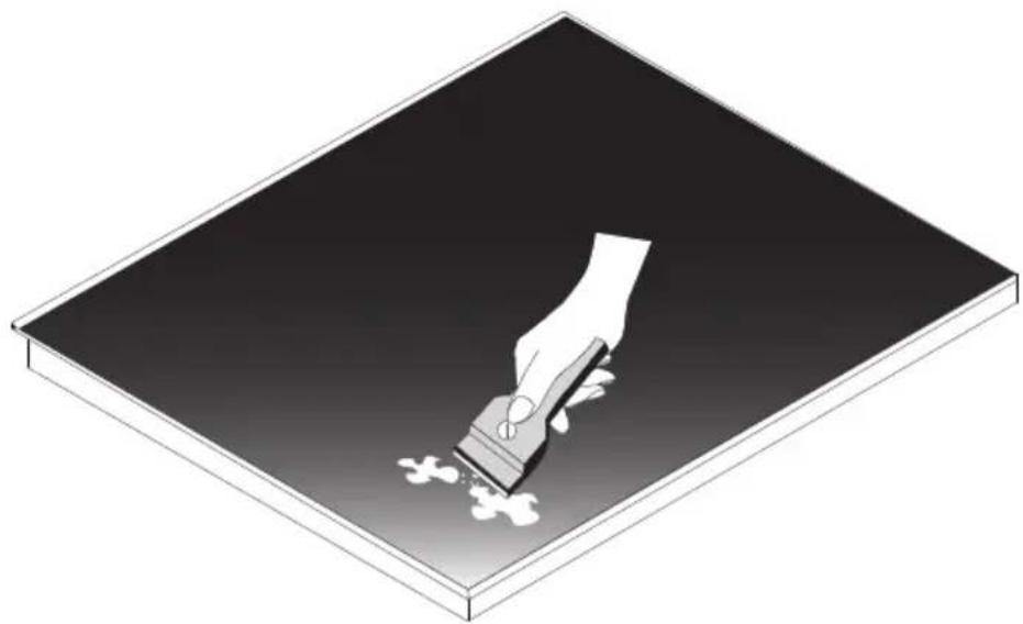
- Maintenance (Fig.9):
Remove any food residue and grease drops from the cooking surface, by using the special scraper provided on request.
Clean the heated area in the best way possible, using suitable products and a paper towel, then rinse with water and wipe away with a clean cloth.
Through the use of the special scraper (optional), promptly remove any pieces of aluminum foil and plastic material, which might have accidentally melted, or sugar or food remains, and/or remains of sugary foods, from the heated surface. In this way, any possible damage to the surface is prevented.
The use of abrasive sponges or irritating chemical cleaners, such as sprays for ovens or cleaning agents is not allowed under any circumstance.
- Use:
Use the touch control system in the corresponding position according to individual cooking needs. Keep in mind that the higher the number, the more heat is produced.
The command offer a convenient handling as selections are performed by touching directly on the display:
- the acitive selection is displayed with high intensity;
• available selections are displayed with a low intensity; - unavailable selections are not lighted.
- Function (Fig.7):
A - On/Off key
B - Control Lock key
C - Pause/recall key
D - Keep warm key
E - Chef Cook
F-Timer level increment / Timer level decrement
G - Timer On
H - Power level setting display
I - Booster
L - Cooking zone display
- Switching the cooking top ON/OFF:
Touch A key to switch the top on, the power led lights up. The power levels for all cooking zones is 0 (the cooking zone displays are OFF).
The cooktop switches OFF automatically after 20 sec. if all cooking levels are set to 0 and no operation is performed. To switch the appliance you have to just touch the A Key. For safety reasons, switching OFF the cooktop via the ON/OFF key is always possible.
EN
- Pan detection:
This cooktop is fitted with an interactive control system that makes it very easy and comfortable to use. After switching on the cooktop, when you put a cookware on the glass, the control system automatically detects it, and the display of relative cookzone shows 0. You then just have to set the expected cooking level.
If you remove the pan on that cookzone, the display shows ♀
- Switching the cooking area ON/OFF:
Put a cookware on the desired cooking zone and press your finger on L keys zone. Then the command shows the H zone. Press H key zone to go to position 9 (max. power) or to go to position 1 (min. power). The power of the single cooking zone can be adjusted in 9 different positions and will be shown on the relative luminous display with a number from "1 to 9".
To swicth OFF that cooking zone you have to press 0 in the H key zone, and automatically the display of the zone shows 0 (in the L key zone).
- Booster function:
The booster enables the induction to dissipate a higher power for a cooking zone for a short period of time (5 min).
As the booster function may reach high temperatures, it must only be used for cooking processes using water. Oil or fat may start to burn if booster is used.
Choose the desire cooking zone L, then type the P symbol on the H zone. The booster for the selected cooking zone is activated, and now the relative display shows P.
To remove the function, select a cooking level for the cooking zone the booster function is currently active. The booster function is terminated and the cooking zone is heated with the new selected cooking level.
- Residual heat indication:
If the temperature of the cooking zone is still high (over 60^ ) after it has been switched off, the relative display will indicate the H symbol (residual heat). The symbol will only switch off when the burn risk is no longer present.
- Timer function:
There are 2 different types of timers. If , more than one timer is set, the timer will always display the lowest remaining time. Both the timers can be adjusted within a range of 1 min to 9 h 59 min.
- Stand alone Timer / Cooking zone Timer:
The Stand alone timer has the behavior of an egg timer. To active this function, ensure that no cooking zone has been selected, the timer show "--", touch the timer, which display 00 flashing for the next 10 sec. Adjust the desired start time digit for digit +/- , do not perform any action for about 5 sec. The timer starts counting backwards. Beneath 10 min, the display shows the current time accurate to the second. If it has reached 0, a signal tone will be emitted. To change the value of the Stand-alone timer, the user has to ensure that no cooking zone has been selected, then touch the timer key, set the new desired time, and finally after 5 sec, the timer starts counting backwards starting with the new time. To disable this function, first of all ensure that no cooking zone has been selected, then touch the timer key, the current time value is displayed flashing, set the Stand-alone time to"000", at this point the function is deactivated.
The Cooking zone Timers can be used to switch a cooking zone OFF automatically after the set time has run out. To activate this function, the user can select the corresponding cooking zone, touch the telative Timer key G, then adjust the desired start time (+/-), if do not perform any action for about 5 sec, the timer starts counting backwards. To change the value of the cooking zone timers, select the corresponding cooking zone, touch the time, and set the new desired time (+/-), do not perform any action for 5 sec., the the timer starts counting backwards starting with the new time. To disable this timer, the user have to set the cooking zone time to "000".
- Pause function:
Pause function is a feature to "freeze" the cooktop for max. 10 min. For example, if the user is leaving the cooktop for a short period of time. During the pause function is active, no cooking zone is dissipating any power, and all timers (including
egg timer) are suspended, moreover the booster function and heat-up automatic is stopped.
To activate this function press C, all displays (L zone) show //. To de activate press C and arbitrary other key within 10 sec.
- Recall function:
This feature enables recovering power levels and timer settings after the cooktop has been switched OFF unintendedly. For example, the cooktop has just been switched off, the user can switch the cooktop ON again via the ON/OFF key (A key) within 6 sec. Then the Pause symbol will flash for 6 sec., now the user have to touch the Pause symbol (C key), at this point the Recall function becomes active. All power levels, timers and heat-up automatics set before are recovered.
- Control Lock key :
Key lock is a functionality intended to lock the keys during the cooktop is in operation or in pause state. This is useful for cleaning purposes as the touch control is unable to differentiate a wet cloth from a finger. When the cooktop is switched ON, the user can touch the Key Lock (B key) for 1 sec., and all keys except the key Lock and ON/OFF are locked. When the key lock is active, pressing all the unlit keys (all except ON/OFF and Key Lock) will result in a reject tone. To deactivate the key lock, touch the Key Lock again, at this point the cooktop can be operated regularly.
- Child Lock key :
This function is useful to protect the cooktop against unintended operation, for example by children. If locked, the cooktop may be turned ON, but no cooking zone, heating level or timer may be selected. To active this function, the user have to power the cooktop ON, touch and hold L zone for an arbitrary cooking zone for 3 seconds, slide the H zone, from 0 to 9. This sequence must be finished within 10 seconds. The display shows L for active childlock. To disable the function: power the cooktop ON, touch and hold L zone for 3 sec., then slide the H zone from 9 to 0 within 10 sec. Now the child lock key is de.activated.
- Bridge function (available just for the octa zones):
EN
Bridging of 2 cooking zones is the connection of 2 single cooking zones, so they can be controlled and will behave as one large cooking zone. This enables using cookware which has a larger bottom surface than a single cooking zone. To active this function, the user have to touch both cooking zone's simultaneously (L zone), in this way the cooking zones are bridged, and one display shows n, and the other the power level. To disable the bridge, the user have to touch both cooking zone's simultaneously. In this way, the cooking zones are split into 2 separate zones again.
- Heat-up Automatic:
Heat-up automatic is a feature which enables heating up a cold pot with full heating power and returning automatically to the desired cooking level. The time during the cooking zone is heated with full power is depending on the selected cooking level. To active the Heat up automatic, you have to hold continuous the desired cooking level (H zone) for at least 3 sec, the display shows A To disable this function, touch and hold the cooking zone command (L zone) for 3 sec. or select as smaller cooking level.
| Cooking level | Heat-up Automatic time (sec) |
| 1 | 48 |
| 2 144 | |
| 3 230 | |
| 4 312 | |
| 5 408 | |
| 6 120 | |
| 7 168 | |
| 8 216 | |
| 9 not available | |
| P not available |
EN
- Chef Cook Function:
Chef Cook function is a features which enables 3 cooking zones with different heating powers. Starting from the left to the right.
To activate this function, touch the Chef Cook function key.
To disable it, touch the Chef Cook function key. The power levels for all cooking zones are set to 0.
The following power levels are set and dissipated as soon as a suitable cookware is placed onto the cooking zones:
| Number zone | Power level |
| 2 | 2 |
| 1 | 6 |
| 4 | 9 |
- Warming level:
This function is used to keep boiled food warm. The power level is between 0 and 1. To activate the warming level you have to select the zone (L zone), and press the D key. The display will show

• Power management:
The hob support power management to prevent the mains connection from overloading. The power management is prioritizing: the cooking zone which heating power has been increasing at last will get the desired heating power, and the other cooking zone will be reduced. The reduction of power will be signaled to the operator by flashing OFF of the cooking level (L zone) and the its power will be reduced.
- Power settings:
The power of the all hob can be set from its maximum [7.4 kW or 3.7 kW (for the hob with two cooking zones)] to a minimum of 1.4 Kw, using a step of 100w (0,1Kw), until a minimum of 1,4w by the user menu.
The User menu is intended for end customer to adapt the Touch Control to his personal needs.
To enter in the User Menu, the command is in standby mode, touch ON/OFF Command to power up the Touch Control. Touch the ON/OFF command again within 3 sec. to set the Touch Control to standby mode again. Special function Command starts pulsating (for 60 sec. max). The menu is automatically exited after that. Press and hold down pulsating the Command. Then press all cooking zone selection Command in clockwise direction, starting with the left front cooking zone selection Command. Skip cooking zone selection Command which are not available.
In the following table there are described the implemented user menu items:
| Item Meaning | Change-able | Value Format | Remark | |
| U0 | Max. power per line conductor | Yes 2.4 ... | 5 | Setting the max. allowed power per line conductor.The max. power is defined inside the service menu and can only be reduced in steps of 0.1 kW until the minimum power. |
| U1 | Filter setting Yes 0,1,2 | Filter changes:0 - 150h (default)1 - 300h2 - 400h | ||
| U2 | Volume for button tones | Yes 0...3 | Adjustment of the volume for button tones0: no button tones1: min. volume2: mid. volume3: max. volumeNotes:For normative reasons, button tones for switching ON and OFF cannot be disabled. They will be emitted with last volume level which has been set before disabling the button tones.Tones for errors are always emitted with max. volume (setting 3) and cannot be disabled | |
| U3 | Volume for signal tones | Yes 0...3 | Adjustment of the volume for signal tones (ex: when timer runs out)0: min. volume...3: max. volume | |
| U4 | Display brightness | Yes 0...9 | Adjustment of the brightness for the display0: Max. brightness...9: Min. brightness | |
| U5 | Timer animation | Yes 0...1 | 0: No Timer animation1: Timer is animated 10 min. before expiration | |
| U7 | Behavior when timer has run out | Yes 0...2 | 0: Signal tone for 120 sec.1: Signal tone for 10 sec.2: No tone | |
EN
EN
• Operation Time Limitation:
The Operation Time Limitation is an additional safety feature to turn OFF cooking zone after certain time with no operation to the corresponding cooking zone by the user. The time after which the cooking zone is turned OFF is mentioned in the table below.
Each user operation related to the cooking zone will reset this time limit.
| Cooking level | Max. Operation time (h) |
| Warming level 1 | 2 |
| 1 | 6 |
| 2 | 6 |
| 3 | 5 |
| 4 | 5 |
| 5 | 4 |
| 6 1.5 | |
| 7 1.5 | |
| 8 1.5 | |
| 9 1.5 | |
| P 5 min. |
TIPSONSAVINGENERGY
- Use a lid whenever possible to minimise heat loss.
- Select a smaller pan when cooking small quantities. A smaller pan uses less energy than a larger pan with very little in it.
• Cook with as little water as possible. - Once food has come to the boil or the oil in the pan is hot enough for frying, reduce the heat to a lower setting.
- Use a pressure cooker to reduce cooking times.
DISPOSAL OF OLD ELECTRICAL APPLIANCES
The European Directive 2002/96/EC on Waste Electrical and Electronic Equipment (WEEE), requires that old household electrical appliances must not be disposed of in the normal un-
sorted municipal waste stream. Old appliances must be collected separately in order to optimise the recovery and recycling of the materials they contain and reduce the impact on human health and the environment.
The crossed-out dustbin symbol on the product reminds you of your obligation regarding separated waste collection. Consumers should contact their local public service or their local dealer for more information on the correct disposal of exhausted household appliances.
THE MANUFACTURER DECLINES ALL RESPONSIBILITY FOR EVENTUAL DAMAGES CAUSED BY BREAKING THE ABOVE WARNINGS. THE WARRANTY IS NOT VALID IN THE CASE OF DAMAGE CAUSED BY FAILURE TO COMPLY WITH THE ABOVE-MENTIONED WARNINGS.
Information for household electric hobs In acc. with regulation (EU) No. 66/2014
EN
| Model name/ identifier 1PIDC30N 1PIDC60N 1PIDC80N 1PIDC90N 1PIDC120N | |||||
| Type of hob built-in built-in built-in built-in built-in | |||||
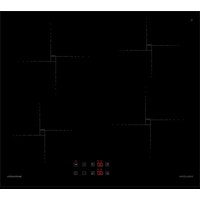
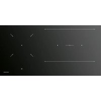
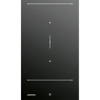
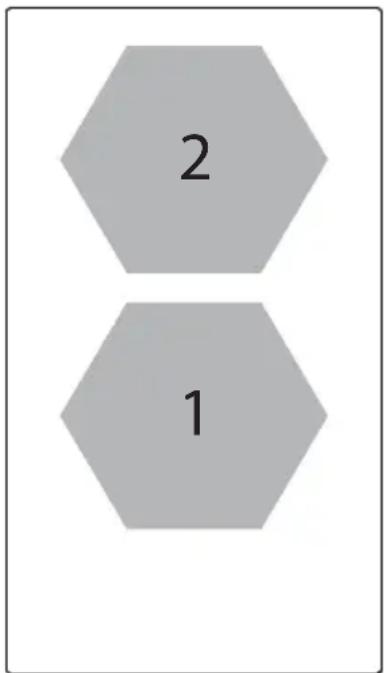
| Number of cooking zones and/or areas | 24434 | ||||
| Heating technologyInduction cooking zones and co-oking areas, radiant cooking zones | 1. = Induction2. = Induction | 1. = Induction2. = Induction3. = Induction4. = Induction | 1. = Induction2. = Induction3. = Induction4. = Induction | 1. = Induction2. = Induction3. = Induction | 1. = Induction2. = Induction3. = Induction4. = Induction |
| For circular cooking zones:diameter of useful surface area/mm cooking zone.For non-circular cooking zones or areas: lenght and width of useful surface area per electric cooking zone or areamm | 1. = Octa2. = Octa | 1. = Octa2. = Octa3. = Octa4. = Octa | 1. = ∅ 1602. = ∅ 2003. = ∅ 2004. = ∅ 160 | 1. = Octa2. = Octa3. = ∅ 200 | 1. = Octa2. = Octa3. = Octa4. = Octa |
| Energy consumption per cookingzone or area calculated per Kg( EC_electric cooking )Wh/Kg | 1. = 189,72. = 189,7 | 1. = 189,72. = 189,73. = 189,74. = 189,7 | 1. = 1792. = 193,33. = 193,34. = 179 | 1. = 189,72. = 189,73. = 193,3 | 1. = 189,72. = 189,73. = 189,74. = 189,7 |
| Energy consumption for the hobcalculated per kg ( EC_electric cooking )Wh/Kg | 189,7 | 189,7 | 186,1 | 190,9 | 189,7 |
text_image
2 1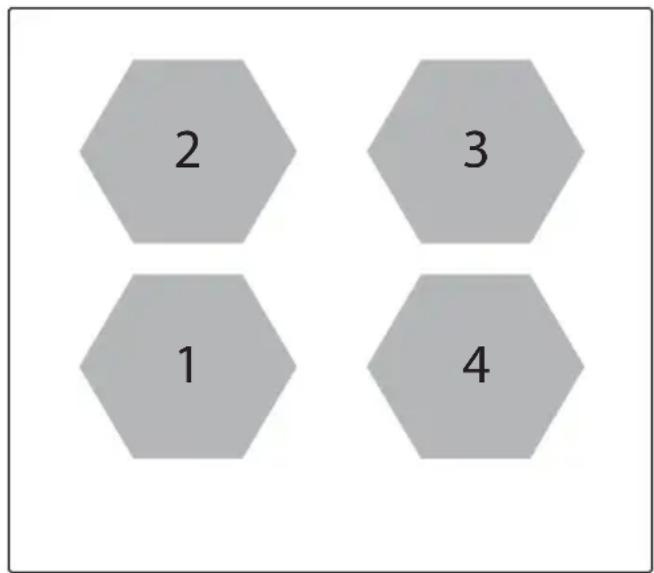
text_image
2 3 1 41PIDC60N
1PIDC30N
EN
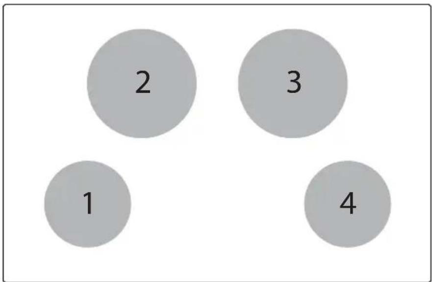
text_image
2 3 1 41PIDC80N
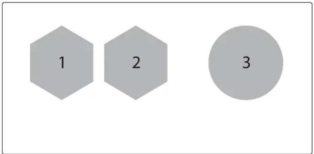
text_image
1 2 31PIDC90N
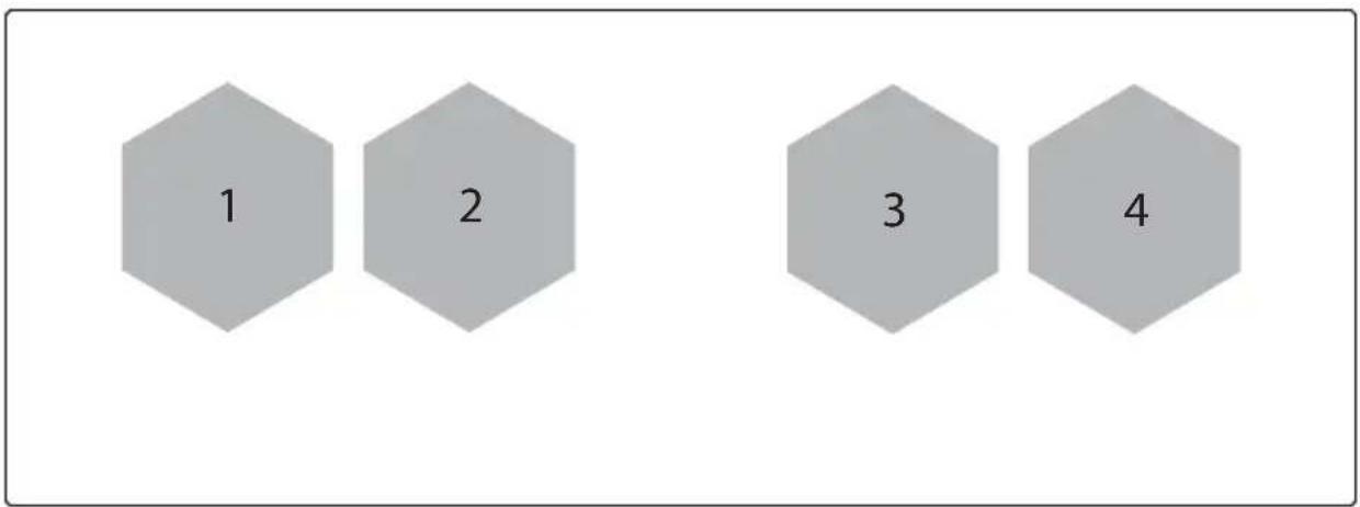
text_image
1 2 3 41PIDC120N
| Error Code | Meaning Behavior | Possible Causes | Remedy | |
| E2 | Overheat of temperature sensor for cooking zone | Corresponding cooking zone is turned OFF | Empty cookware Do not heat-up empty pots | |
| Wrong cookware Use appropriate cookware | ||||
| Pot or glass temperature is too high. Electronic temperature too high | Cool down system | |||
| E3 | Wrong pot Corresponding cooking zone(s) is/are turned OFF | Cookware is losing its magnetic characteristics | Use appropriate cookware | |
| Internal error in generator's circuitry | Contact technical support | |||
| Pot creates on the module an improper operating point which can destroy devices, e.g IGBT. | 1. The error is automatically cancelled after 8s and the cooking zone can be used again. in case of further upcoming errors the pots have to be changed.2. Contact technical support. | |||
| E4 | Configuration error Cooking zone cannot be turned ON | Induction module is not configured yet | Contact technical support. | |
| Induction module configuration data error | Erase and re-configure cooking zone.Contact technical support. | |||
| E5 | No communication between User Interface and Induction Generator | Cooking zone cannot be turned ON | LIN cabling or power supply cabling defective (e.g. missing line conductor) | Contact technical support. |
| No mains voltage on slave boars | Contact technical support. | |||
| Internal error in generator's or filter's circuitry | Contact technical support. | |||
| (Mixed version) HiLight Relay Voltage Error - Defect hardware device | Contact technical support. | |||
| Error configuration data | Contact technical support. | |||
EN
| E6 | Power supply voltage is out range (voltage and/or frequency) | Cooking zone cannot be turned ON | Power supply voltage is out of range (see technical data for details) | Contact technical support. |
| Wrong mains frequency or mains voltage phase signal problems | Contact technical support. | |||
| Internal error in generator's circuitry | Contact technical support. | |||
| E7 | Internal error Cooking zones are turned OFF | - | Contact technical support. | |
| E8 | Fan failure Corresponding cooking zone is turned OFF | Fan blocked by dust or fabrics | Clean and remove foreign bodies | |
| Fan or module electronics defective | Contact technical support. | |||
| E9 | Temperature sensor error for cooking zone | Corresponding cooking zone is turned OFF | Temperature sensor line for cooking zone is open or short-circuited | Contact technical support. |
| EA | Internal error Cooking zones are turned OFF | - Contact technical support. | ||
| Flash checksum error | Contact technical support. | |||
| IGBT- Idle current too high | Contact technical support. | |||
| Heat sink sensor broken or shorted | Contact technical support. | |||
| EEPROM- data Error | Contact technical support. | |||
| Coil selection error Defect inductor or wrong inductor | 1. Re-plug2. Contact technical support. | |||
| MCU internal register setting | Contact technical support. | |||
| Gate power voltage out of range | Contact technical support. | |||
| ADC startup test failure ADC bandgap voltage invalid | Contact technical support. | |||
| Capacitor Control wrong signal Defect hardware device | Contact technical support. | |||
| EH | Temperature sensor stuck for cooking zone | Corresponding cooking zone is turned OFF | Not enough temperature change after switch on the hob | Cool down the glass |
| No temperature change (min. 10 K / 5 min) after cooking zone is energized | Contact technical support. | |||
| ER03 | Continuous key activation detected | Cooktop switches off after 10 sec. | Water or cookware placed on TC's SmartKiis | Remove water or cookware from the glass |
| ER20 | Internal error inside TC Cooktop switches off | - Contact technical support. | ||
| ER21 | Over temperature Cooktop switches off | Temperature sensor on TC has detected a temperature > 85°C | Let the cooktop cool down (error disappears if temperature is <75°C). Contact technical support. |
| ER22 | Internal error inside TC Cooktop switches off after3.5-7.5 sec. | - Contact technical support. | |
| ER31 | Configurations inside Touch Control and induction are incongruent | ER31 is displayed continuously | The configuration data inside the induction generator is different from the configuration inside the TC |
| ER36 | Internal error inside TC Cooktop switches off | - Replace TC | |
| ER42 | Secondary power supply implausible | 12V or 5V too high / too low | |
| ER47 | No communication to at least one LIN subscriber | ER47 is displayed continuously | LIN cable damaged No power voltage supply for LIN subscriber LIN subscriber defective |
EN