
Comtesse - Model making Krick - Free user manual and instructions
Find the device manual for free Comtesse Krick in PDF.

User questions about Comtesse Krick
0 question about this device. Answer the ones you know or ask your own.
Ask a new question about this device
Download the instructions for your Model making in PDF format for free! Find your manual Comtesse - Krick and take your electronic device back in hand. On this page are published all the documents necessary for the use of your device. Comtesse by Krick.
USER MANUAL Comtesse Krick
Building Instruction
COMTESSE
Order-No. ro1072
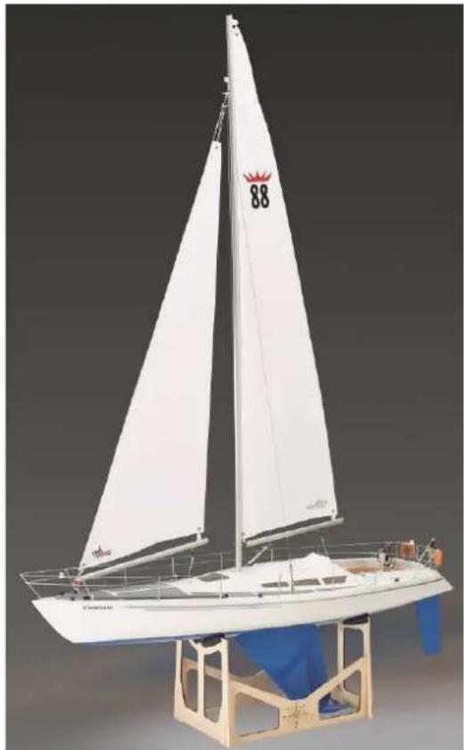
We congratulate you on your purchase of the model sailing yacht "COMTESSE". This model is essentially intended for beginners, but also gives the experienced ship model builder a lot of pleasure during construction and operation.
To build the model you will need the following adhesives, fillers and paints:
- Superglue Krick/Deluxe Roket Hot thin (Order-No. 44050)
- Superglue Krick/Deluxe Roket Rapid medium (Order-No. 44051)
- Two-component adhesive 5 min epoxy 100g (Order No. 80479)
-
Wood glue UHU Wood waterproof 75g (Order-No. 48515)
-
Two-component adhesive Stabilit Express 30g (order no. ro5015)
- Pore Filler (Lord Nelson Pore Filler Order No. 80110)
-Colour spray white (order no.320010), blue 210 (order no.316210),light grey (primer). - Masking tape 493269
- Ballast (order no. 60102) 2 packs of 1000 gr each
- Epoxy resin Aeropoxi Order no. 44010
The following tools represent the basic equipment for building the "COMTESSE":
- Handicraft knife (Order No. 416002)
- Hand drill (order no. 473841)
- Sandpaper Files (Order No. 491016)
- Sanding block (order no. 490080)
- Abrasive paper grain 180, 320, 400 and 600 (set order no. 490190)
- Round file approx. 6mm
- Drill 0.1mm 1.5 mm,2 mm,3 mm,4 mm,5 mm,6 mm
- Side cutter (Order No. 455550)
PVC adhesive tape or paper adhesive tape is also required for masking when varnishing. In the Krick assortment you find the suitable adhesive tape e.g. order number 493269. This adhesive tape is available in different widths. Do not use crepe tape!
The construction of the model is facilitated by the numerous photos of the construction phases.
Before starting building, you should clearly identify these parts using the parts list, building instructions and construction plan. During the construction process, only the parts you need should be removed carefully and with the help of a sharp knife.
It is much easier for you to start building ship models if you contact an experienced model builder. He can help you with questions and problems and gives you the guarantee that your own "COMTESSE" will be a working and beautiful model. If you do not have an experienced model builder in your circle of acquaintances and/or friends, please contact a model building club in your area or ask the model building dealer from whom you purchased this kit. In every ship model building club you will find active ship model builders who will be happy to help you
We wish you much pleasure with the following construction of your model.
It is important for the bonding of laser parts that the burn-off at the laser edges is grinded off. These burnt edges do not bond with adhesives of any kind.
Technical data
Hull length 950 mm
Width 230 mm
Draught approx. 210~mm
Total height 1500 mm
Mast height 1200 mm
Sail area approx. 30dm^2
Ballast content approx. 1800 gr.
Total displacement approx. 3200 gr.
Accessories not included but required
1 ro 1073 Fitting set Comtesse
Contents: railing supports, railing cables, parts for bow and stern pulpit, spinnaker trees, rudder stand, compass, life jackets, winches, cleats and many other small parts
1 servo for rudder adjustment
Optional accessories
1 ro 1071 Wing keel
1 ro 1074 Propulsion set Comtesse
Suitable remote control system
Basically, a 2-channel remote control (e.g. roF2201) is sufficient to control the rudder and the sail control. If the propulsion set is also installed, a remote control with at least 3 channels (e.g. roF4024 or roF4009) is required.
General instructions for the construction process
The numbering of the parts essentially corresponds to the sequence of the construction process, whereby the number in front of the point indicates the construction stage and the number behind the point indicates the corresponding component. Before the start of construction, please obtain an overview of the respective construction steps in conjunction with the building instructions and the plan, the instruction steps and the parts list.
Prime all wooden parts once or twice with pore filler before installation. Sand with fine sandpaper after each coat. Roughen the adhesive surfaces with sandpaper before gluing.
The construction of the model
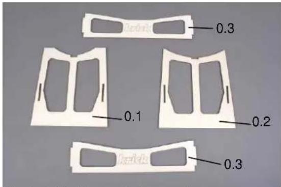
Stage 0, the boat stand, parts 0.1 - 0.3
Fig. individual parts of the stand
Glue the boat stand together from parts 0.1 to 0.3. Grind all edges with sandpaper so that the burn-off residue is removed from the laser cutting.
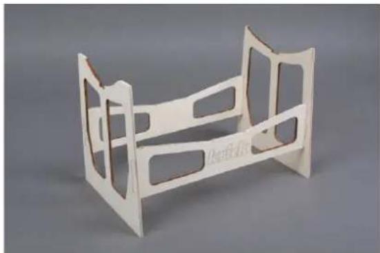
Fig. stand glued together
Stage 1, preparations for hull, parts 1.1 to 1.9
Grind off the surrounding seam on the hull.
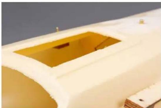
Cut out the dome at the rear. Mark the opening for the sliding hatch as seen from above and cut it out by scribing several times.
Dome and sliding hatch are shown in drawing 1 A with grid pattern.
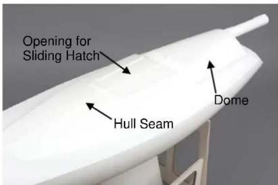
Fig. hull processing
The following holes must be drilled in the hull:
3 mm for eye bolts 1.6 and 1.14 for jib suspension and shrouds.
5 mm for the rudder bearing
6 mm for the mast bearing
Optional: 6mm for the sterntube if the drive set is to be installed. See also section X Installation of the propulsion unit.
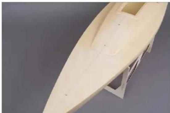
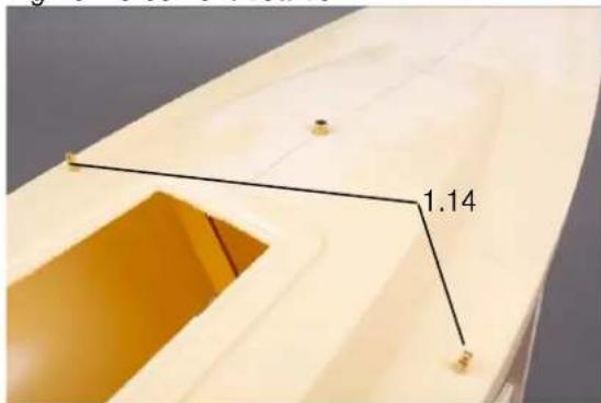
Fig. holes in deck
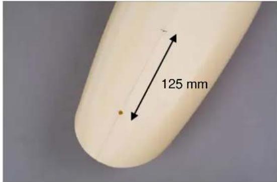
Fig. holes on underside of hull
Drill the holes exactly according to drawings 1A and 1B.
When drilling the holes, drill very accurately to avoid large gaps, especially with the rudder bearing D 5 mm. The tube should fit very tightly so that it can be easily aligned and remains in position until the adhesive has hardened.
Optional:
If the propulsion set is to be installed, drill the hole for the stern tube D 6 mm at a distance of 125mm from the rudder tube.
Make the front reinforcement and attachment for the jib mount from parts 1.2 to 1.5.
Prime all wooden parts with pore filler before gluing them into the hull.
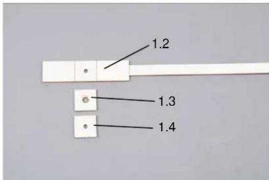
Fig. front reinforcement board
After gluing parts 1.2 and 1.3, insert the hexagon nut M3 and glue part 1.4 to the end. Make sure that no adhesive gets into the thread.
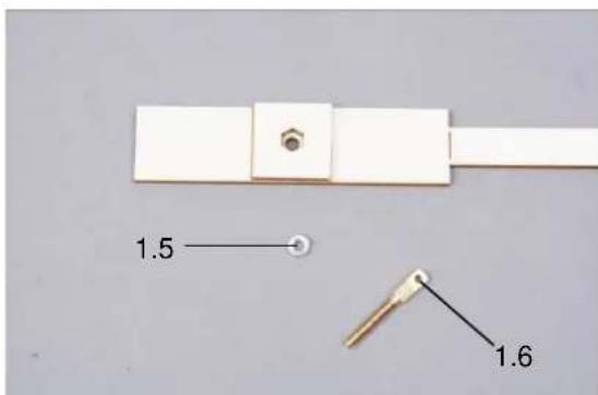
Fig. front reinforcement board with nut M 3 and eyebolt M 3
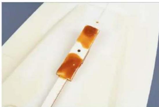
Coat the upper side of board 1.2 with StabilitExpress. Insert the board with the handle into the hull and screw the eye bolt 1.6 through the deck from above to secure and tighten. Clamp the handle to the edge of the sliding hatch until the adhesive has cured. Make sure that no glue gets to the screw thread, otherwise the eyebolt is stuck and cannot be loosened any more. After the adhesive has dried, break off the handle at the predetermined breaking points.
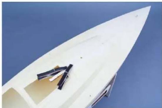
Fig. reinforcing board in position
Now also make the lateral reinforcement boards for the shroud fastening in the same way from parts 1.10 to 1.12.
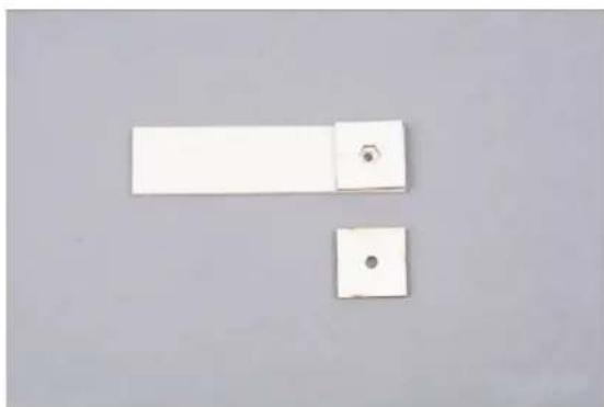
Fig. lateral reinforcement boards
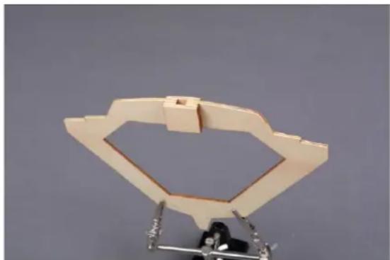
Now the main bulkhead can be made with the mast mounting from parts 1.7 to 1.9.
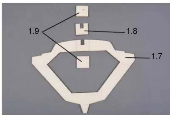
Fig. parts main bulkhead
First glue part 1.8 to part 1.7 at the marked point. Then glue both parts 1.9 from the front and rear over the cutout.
Now paint the frame and the reinforcement boards several times with pore filler.
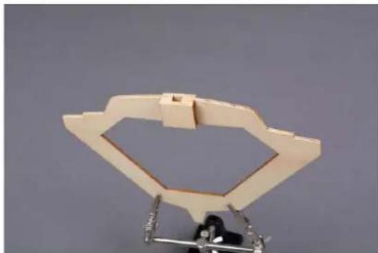
Fig. main bulkhead glued
Now the bulkhead can be fitted into the hull. Push the bulkhead into the hull until it is vertically under the hole for the mast foot. To check, insert the mast foot through the hole.
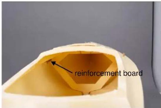
Fig. reinforcement boards
Now push the reinforcement plates for the shroud fastening into the slots in the frame and check the position by screwing in the eyebolts, part 1.14.
If everything fits, fix the frame with super glue in some places. Then glue the frame with Stabilit Express. Make sure that no glue gets into the side trays for the reinforcement boards of the walls.
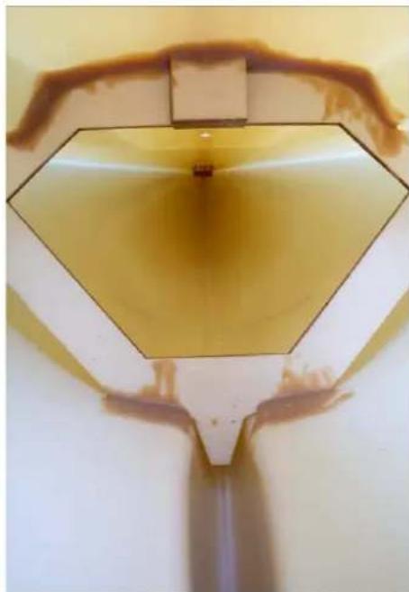
Fig. frame glued in
In the next step glue in the two reinforcement boards for the shrouds.
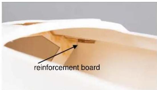
Fig. reinforcement boards
Fit the rear hull reinforcement 1.15 and glue with Stabilit Express.
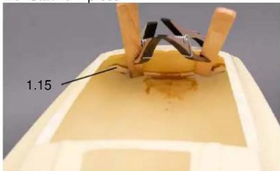
Fig. rear hull reinforcement
To press on the hull reinforcement, wooden strips can extend the clamps.
Stage 2, the rudder system, parts 2.1 to 2.8
Push the rudder bearing 2.1 into the hull from below and push the rudder support 2.2 over it.
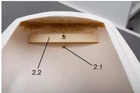
Insert the rudder from below and align it. Align the rudder so that it is exactly aligned with the keel when viewed from behind. When viewed from the side, align the rudder so that it is evenly spaced from the hull over its entire width. The rudder must be freely rotatable in both directions of rotation.
Fix the rudder bearing and support with super glue.
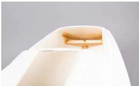
Fig. glued rudder bearing
Then glue the rudder bearing and the support with Stabilit Express.
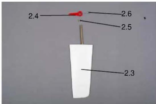
Install the rudder using parts 2.3 to 2.6.
Stage 3, RC board installation and ballast
In the next step make the RC board and glue it into the hull.
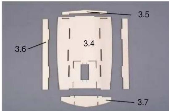
Fig. parts for RC board
Sand the parts cleanly at the glued joints and glue them together.
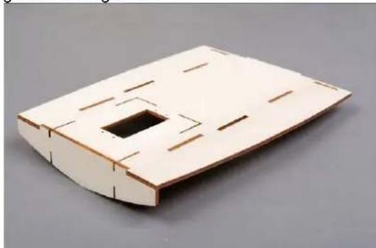
Fig. RC board ready for installation
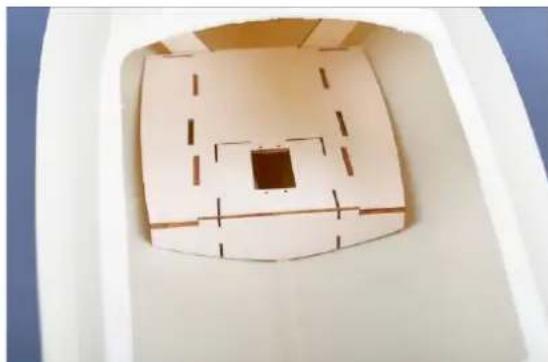
Fig. RC board positioned in hull
Before gluing the RC board in place, coat it several times with a pore filler.
The RC board can only be glued in after the ballast has been filled. If the drive set is to be installed at a later date, the cut-out for the motor holder can also be cut out later.
If you operate the Comtesse without driver ro1074 and without wing keel ro1071, fill 1800 g ballast shot 60102 into the keel. Cover the granulate with epoxy glue so that the layer is firm and complete.
If you want to install the drive, you have to reduce the ballast by 200 g, i.e. fill in 1600 g. If you also want to use the wing keel ro1071 with 800 g, you have to further reduce the inner ballast. We recommend reducing the internal ballast by 600 g to 1200 g or to 1000 g respectively.
By lightly tapping against the side of the ship, you can compact the ballast and reduce the voids to a minimum. As an intermediate layer you can fill in a layer of epoxy resin (e.g. Aeropoxi, order no. 44010) to fix the ballast grains. In any case, you must do this as the last layer. The ballast should be covered smoothly with resin. If the resin runs off too deep into the keel, refill one layer again. Do not fill in too much resin at once, as the resin heats up during curing and can otherwise deform the hull.
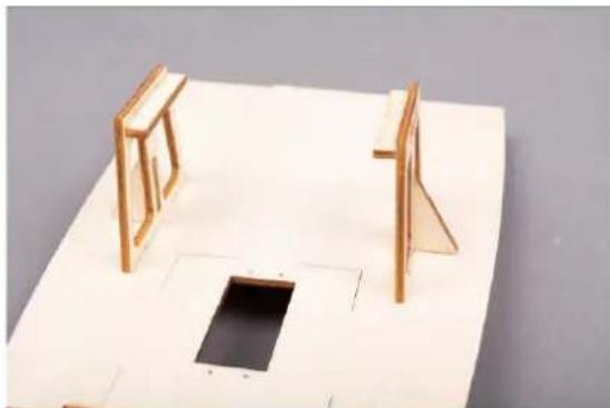
After the ballast is glued in the hull, the RC board can be glued in place. Next, assemble the frame for the sail winch from parts 3.8 to 3.12.
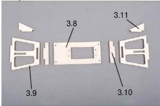
Fig. Sail winch frame
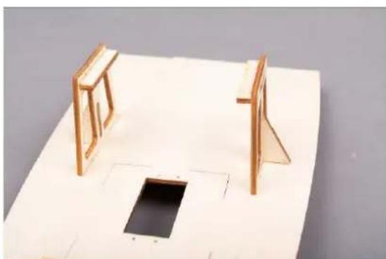
Fig. Supports glued
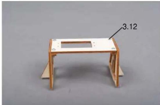
Fig. Sail winch frame complete
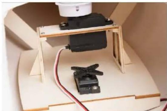
Fig. Sail winch frame on RC board
The winch frame can now be put for a test on the RC board. If everything fits, paint the winch frame several times with pore filler and then glue it to the RC board.
You can now make the connection between the servo and the rudder.
Place the servo in the provided recess in the RC board and attach parts 2.7 and 3.12 to the servo and rudder. Connect with the two collars.
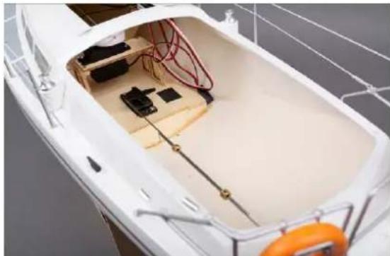
Fig. rudder linkage

Stage 4, cockpit and sliding hatch parts 4.1 -4.18
Fig. cockpit
Trim the cockpit 4.1 according to the markings. A Lexan scissor with short, stable cutting edges (e.g. order no. 455533) is best suited for cutting out.
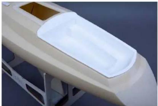
Fig. cockpit fitted in hull
Insert the cockpit into the hull opening and fit. If necessary, regrind the edges.
Screw the cockpit to the hull using 6 countersunk screws 4.23. Slightly countersink the 6 holes with a countersink or a larger drill so that the screws are flat.
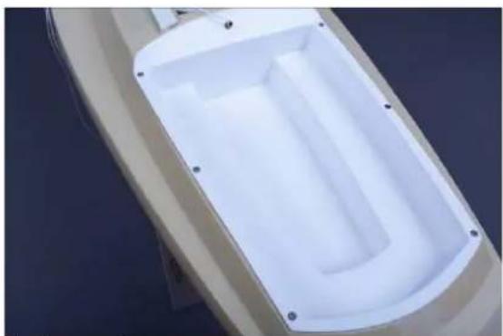
Fig. cockpit mounting
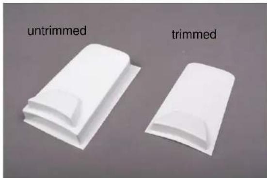
Fig. sliding hatch
Cut the sliding hatch 4.13 according to the markings and place it over the hull opening. Check that the sliding hatch fits into the recess, otherwise sand the edges.
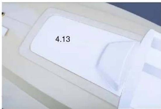
Fig. fitting the sliding hatch
Adjust the frame 4.14 and glue it on e.g. with UHU Allpast (order no. 48410).
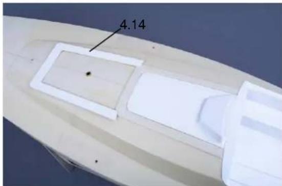
Fig. sliding hatch and frame
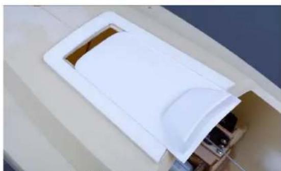
Fig. glued frame, fit sliding hatch
Make the two sheet feedthroughs from parts 4.10 to 4.12.
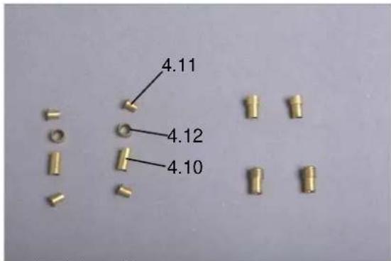
Fig. sheet feed-through
Glue the stop ring 4.12 onto the sleeve 4.10 and then glue in a tubular rivet from above and below.
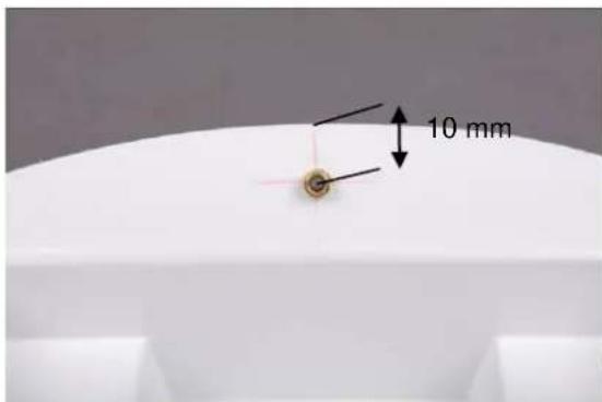
Fig. sheet feed-through in the cockpit
Mark and drill in the middle of the cockpit, 10 mm from the top edge, the hole for the mainsail sheet feed-through (sheet from the winch to the mainsail). If necessary, file a little at the edge of the cockpit cut-out in the hull so that there is enough room for the sheet feed-through.
Glue the two bushings in place. Here superglue can be used.
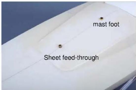
Fig. sheet feed-through jib sheet and mast foot
Also glue the mast foot part 4.18 into the hull.
Now we can paint the model. To do this, align the model in the stand so that the nose tip is 33cm high.
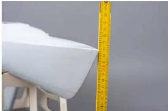
Fig. Align bow
Now draw a line 25cm high, as waterline.
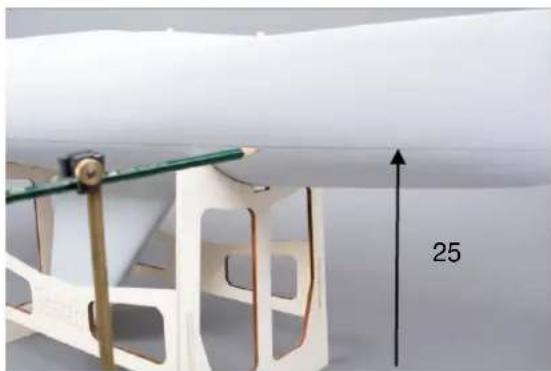
Mark waterline
You can use the waterline marker (order no. 473780) for this purpose.
You can now, depending on what you want to paint first, mask the corresponding area of the hull and paint the rest. Note, that it is advisable to paint the light colour first and then the dark one.
The sliding hatch and the cockpit are painted separately.
Stage 5, the mast, parts 5.1 to 5.21
Glue the pin part 5.2 with 5 min epoxy into the mast so that it protrudes 14mm
Drill the mast part 5.1 according to detail drawing "5A" and dimensional data.

Fig. drill holes for downhaul and boom fitting

Fig. holes for shroud mounting
Bend 2 plates part 5.11 and 5.13 as shown in the illustration.
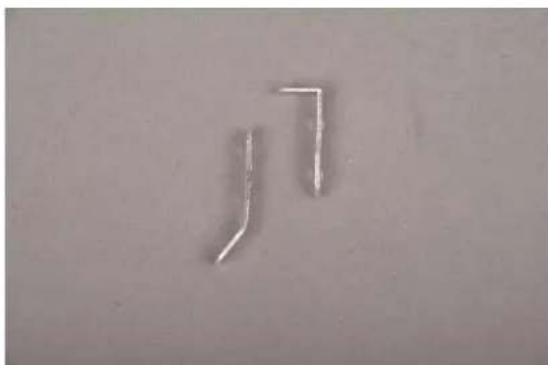
Fig. lamp holder and hanger for shrouds
Screw the two parts to the mast with 2 screws 5.14.
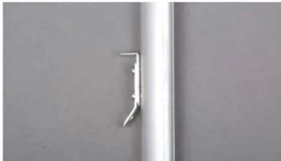
Fig. hanger for shrouds and console for top light
Hook the S-hook 5.3 into the eyebolt 5.4 and screw on a nut 5.5. Insert the ring bolt through the mast and tighten with a second nut.
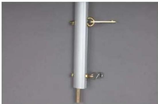
Fig. mounting of boom fitting and downhauls
Hook the plate for the boom into the eye socket. Drill a 2.5mm hole for this purpose first. Tighten the eyebolt for test purposes. The plate is glued into the main boom in stage 6.
The shrouds 5.9 are made from one piece of steel wire. To do this, cut a piece of steel wire strand for the two shrouds part 5.9 to 2.2m in length. Pull the steel strand through the lower hole of the mast plate to the middle and press it directly underneath the plate with a crimp sleeve 5.10.
Stage 6, Booms, parts 6.1-6.15
Provide the main boom 6.1 with 2 holes 2mm according to drawing "6A".
Screw one nut M 2 part 6.4 each on 2 ring bolts 6.2 up to the end of the thread. Insert the eyebolts through the holes and tighten with 2 nuts M 2.
Glue the plate 5.6 with 5 min epoxy on the side with the hole spacing 68~mm
Now push the plate with the side, not deburred for the eye-screw, into the boom below the bar and glue it in place.
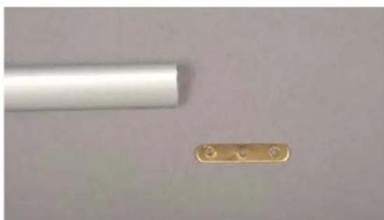
Fig. Position plate
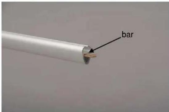
Fig. Position plate
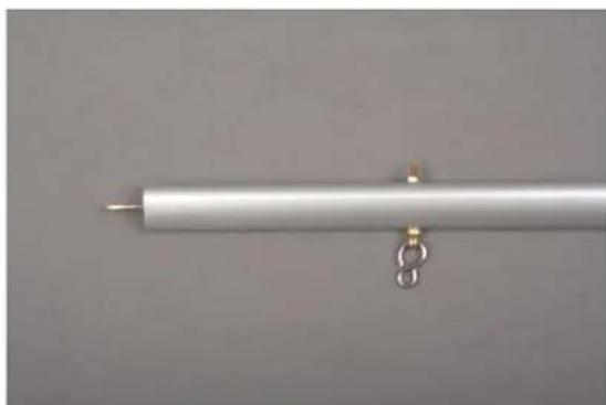
Fig. S-hook
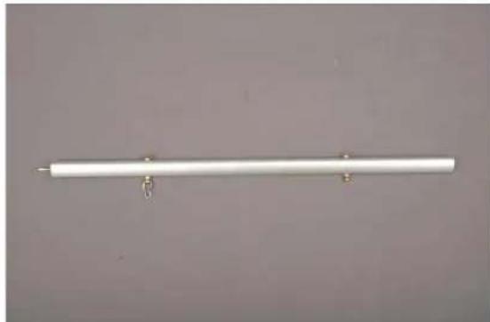
Fig. boom complete
Drill the jib boom 6.6 according to detail drawing "6B". File a rectangular slot 2 × 5 mm under the front cross hole.
Mount the eyebolt with the nuts M 2 as described for the main boom.
Push a swivel from below into the slot of the boom and fix it with the screw 6.11 and nut 6.12.
Hook an S-hook part 6.13 into the front end of the boom.
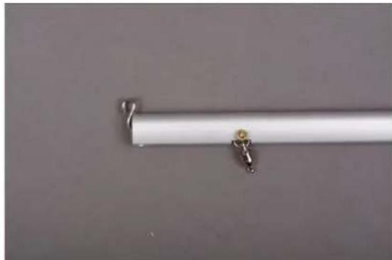
Fig. Swivel and S-hook
An S hook 6.5 into the front eyebolt.
Stage 7, the mainsail, parts 7.1 - 7.9
First glue the reinforcing tape 7.1 to the luff. Mark every 15cm with a pencil from the edge at a distance of 9.5mm . Glue the reinforcing tape along the marking on one side and then turn it over.
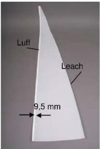
Fig. Mainsail
Next cut the reinforcing tape 7.2 into 25 × 25 mm wide triangles. Stick these as reinforcements on both sides at the corners.

Fig. reinforcement corners
Now divide the slotted tube 7.3 into 10 mm pieces. Push these pieces onto the luff as luff sliders at a distance of 8 - 10 cm and fix them with superglue of medium viscosity.

Fig. luff sliders
Stage 8, the foresail, setting up the rig, parts 8.1 - 8.14
The next step is to make the foresail.
Make the forestay from the remaining wire rope. First make a loop at one end, using a crimp sleeve 8.12.
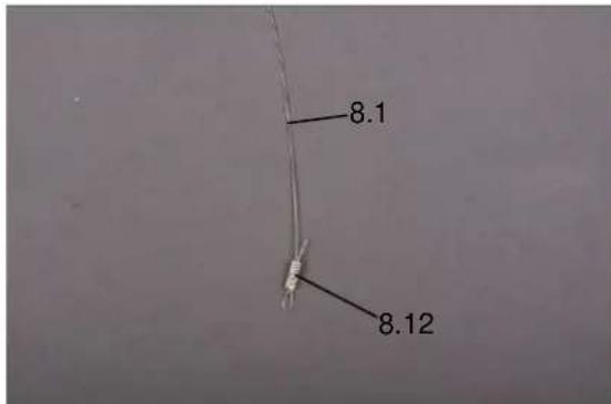
Fig. loop
Press the crimp sleeve flat with a pair of pliers.
Mark the fold edge of the luff at a distance of 15 mm from the leading edge of the sail.
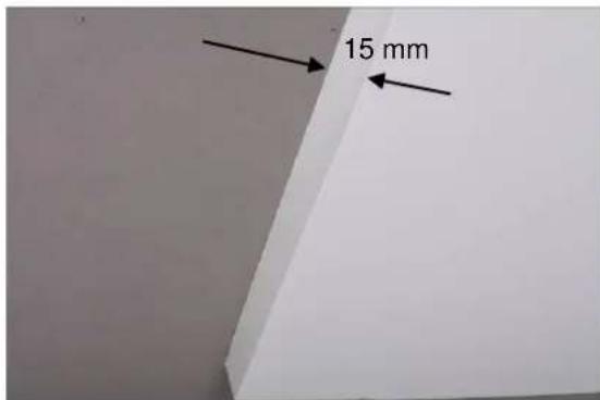
Fig. fold edge
Kink the sail at this line and fold the edge with a ruler or similar. Then glue the double-sided adhesive tape part 8.5 to the front edge so that a hemstitch is created when you glue it to each other.
The forestay is inserted into this hemstitch.
This can be done in 2 ways. You can either fix the forestay on your worktable in such a way that it lies in the folded edge and then glue the hem over it. Or push the finished forestay later into the previously glued hollow hem. Makesure that the forestay can move freely.
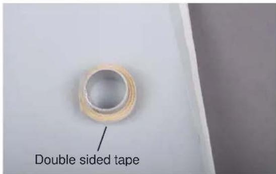
Fig. Apply adhesive tape
Now you can start setting up the rigg.
Fig. eyelets mainsail
Pull off the covering tape and glue the edge against each other.
To do this, first prepare the two shroud tensioners from parts 5.18 to 5.21.
Fig. forestlay
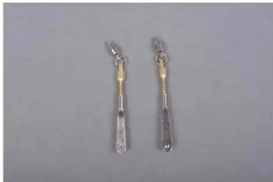
Fig. shroud tensioner
Now also make a loop at the other end of the forestay so that the final length is 950mm .
Now fasten the foresail to the foresail boom.
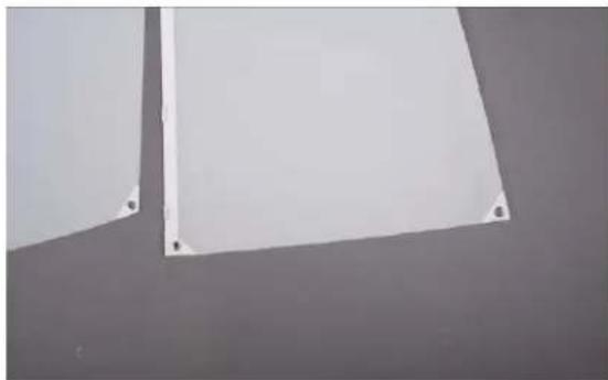
As with the mainsail, glue the reinforcements of the 8.6 adhesive tape onto the corners of the foresail.
For this purpose make the bracket from parts 6.14 to 6.16.
Finally, place the eyelets in each of the 3 sail corners to fasten the sails. To make the holes, sharpen the punch 7.10 and punch the holes in the corners (light hammer punch).
Now put one of the eyelets (rivet 7.5) with washer 7.6 through each hole and put another washer 7.6 on the opposite side. Now the eyelets can be flanged around. This can be done with a suitable riveting pliers or punch or simply with a Phillips screwdriver and light hammer blows.
Fig. bracket and top fitting
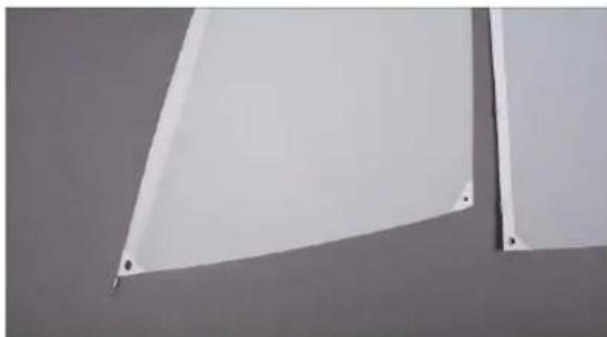
Fig. eyelets foresail
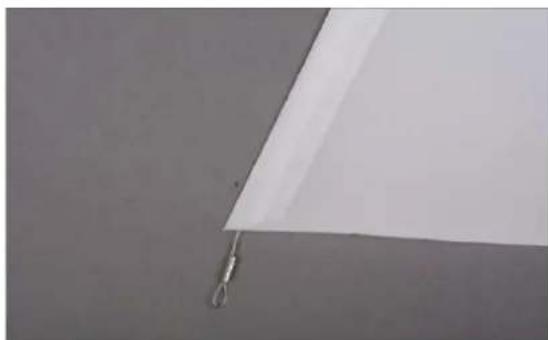
Attach the forestay to the S-hook. Tie the sail to the bracket with strap 8.10 and attach the carbine 6.17 to the boom.
Fasten the jib sail with a short strap 8.10 in such a way that an even distance is maintained between the lower edge of the sail (lower leech) and the foresail boom.
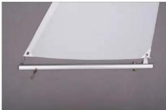
Fig. foresail with foresail boom
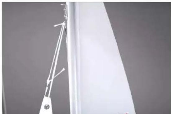
Fig. foresail attachment
Proceed with the main boom as with the foresail. The bracket is made as with the foresail boom.
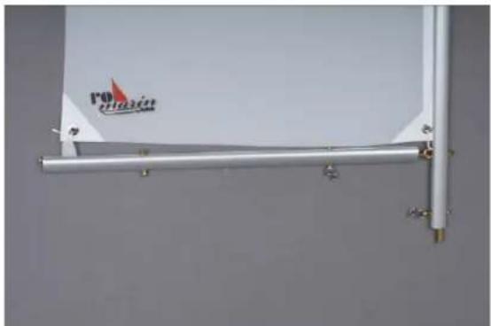
Fig. main boom
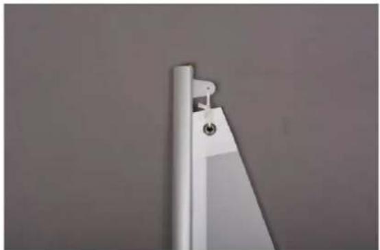
Fig. top fitting
Make the top fitting from parts 5.15 to 5.17 like the bracket fitting of the foresail and main boom and fix the sail with a strap.
Tie a 400 mm long piece of rigging yarn to the upper loop of the foresail as a luff line 8.11.
Place the mast in the mast foot and hook the carbine into the eye bolt 1.6 of the foresail boom's swivel bearing.
Guide the rigging yarn piece 8.11 through the bracket on the mast, tighten slightly and knot.
Now attach the shrouds to each side of the hull. Slide a crimp sleeve onto the shroud rope and through the hole in the shroud tensioner swivel. Slide through the crimp sleeve and push it downwards. Prepare the 2nd shroud in the same way. Align the mast vertically in all directions and then press the crimp sleeves together with a pair of pliers.
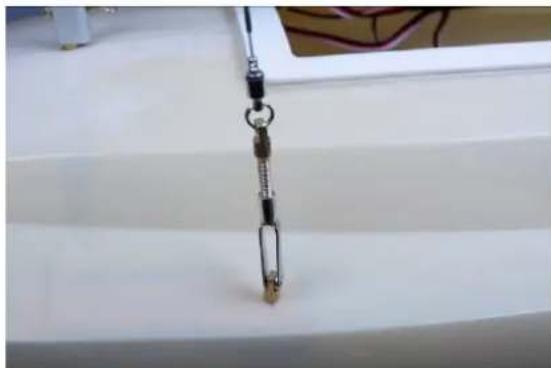
Fig. shroud mounting
Now install the sail winch (not included in the kit).
Lead the two sheets 8.13 and 8.14 through the deck ducts and fix them to the drum of the winch. Screw the winch to its place. Bring the winch with the remote control stick into its forward position (sail / sheet completely open, free). Now insert the drum of the winch and fix it with the central screw. Now move the stick of the remote control to the rear position (sail / sheet completely closed, tightened). Now the necessary sheet length is wound on the drum.
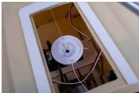
Fig. sail winch mounted
Knot in a carbine hook at the free end of the sheets. Adjust the foresheet so that the foresail boom opens approx. 40~mm . For the main boom, adjust the sheet so that the boom is absolutely in the middle of the hull.
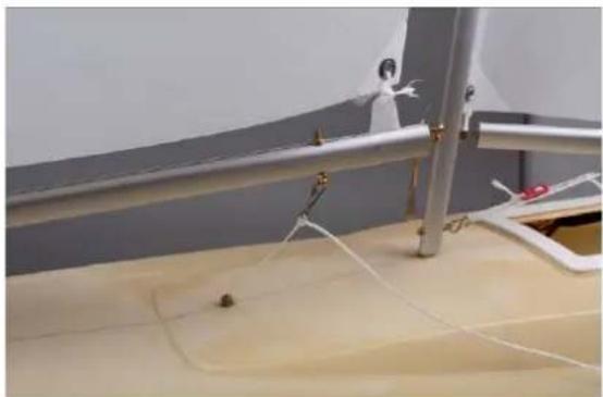
Fig. foressheet
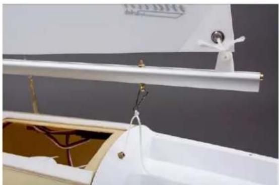
Fig. main sheet
For the following works it is necessary to remove the rig (mast with sails and trees).
To do this, unhook the sheets with the snap hooks. Release the tension of the shrouds and unhook the two shroud tensioners. Finally unhook th snap hook from the foresail boom. Now the complete rig can be removed.
Now would be the latest time to paint the hull.
Stage 9, bow and stern pulpit, parts 9.1 - 9.19
For the construction of the bow and stern pulpit, fixtures must be manufactured. Cut out the drawings "9A" and "9B" on plan 1 and glue them with paper glue onto a thicker wooden board.
Drill the holes 2mm
Make the spacer blocks "D" from balsa wood and glue them to the drawings with superglue according to the dotted lines.
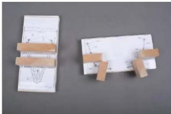
Fig. auxiliary devices
Before assembly, the tube parts must be cut with some excess length, which is not described in detail every time.
Bend the bow pulpit parts 9.1 and 9.2 as well as the railing supports 9.3 and 9.4 according to the detail drawing "9C" and cut them exactly to length.
Provide the railing supports 9.3 and 9.4 for the pulpit with the washers 9.5 and insert them into the holes of the mounting board.
Push three split pins 9.6 onto the upper bow pulpit rail. To do this, carefully expand the eye of the split pins according to the diameter of the railing. Push the split pins into the reling supports at the top.
Place the lower pulpit rail 9.2 on the blocks and fix it with needles.
Align the complete pulpit. Solder the railing supports to the upper and lower pulpit rails. Slide the washers onto the board and solder them to the railing supports as well. It must be soldered short but hot.
Solder in the pins 9.9 for the railing cables. Drill small holes in the railing
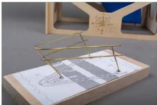
Fig. bow pulpit
Make the rear pulpits on the board with the drawing "9B". Care must be taken that a left and right stern pulpit are manufactured.
Bend the upper railing cables 9.10 and 9.11 and the lower railing cables 9.12 according to drawing "9D".
Cut the railing support 9.13 to length.
Fit slides and supports with washers 9.14 and push them together with split pins 9.15.
Align and solder the parts as described for the bow pulpit using the spacer blocks.
Drill and solder the holes for the pins 9.16 of the railing cables.
Bend the holders 9.17 for the life jackets and solder them to the upper rear pulpit rail.
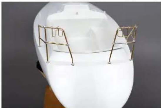
Fig. rear baskets with holders for life jackets
Now you can paint the pulpit and the two stern pulpits.
Stage 10, Railing and bathing ladder, parts 10.1 - 10.11
Once the hull has been painted, the bow and stern pulpits and railing supports can be attached.
Drill the holes for the railing supports 10.1 with 2mm at a distance of 120~mm , starting at the bow pulpit. Insert the stanchions, do not glue them.
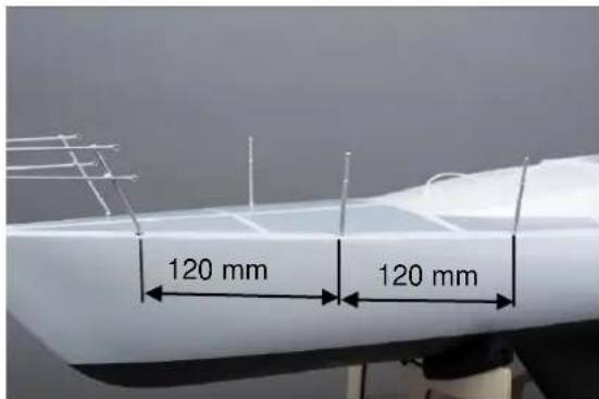
Fig. Installing railing stanchions
Cut the railing cables 10.2 to approx. 1m (extra length).
Provide the railing cables with a crimp sleeve 10.3 one after the other, push it through the front split pins 9.9 and push the end through the crimp sleeve and press it together.
Guide the railing pull through the railing supports, aligning the supports.
Tension the railing cable slightly, thread it through the rear split pin 9.16 and press it together with a crimp sleeve 10.3. Now the railing stanchions can also be glued.
Bend the U-shaped bathing ladder bracket 10.4 according to drawing "10 A".
Push on and solder the rungs 10.6 provided with 2 split pins.
A soldering aid consisting of a small board with corresponding spacer strips helps soldering.
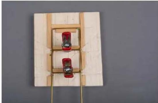
Fig. soldering aid bathing ladder
Fit the lower rung with split pins 10.5 and insert into the ends of the brackets and solder tightly.
Cut the rotation axis to length, put it into the rung 10.7 with the same protrusions left and right and solder it in - drawing "10B".
Bend the bathing ladder according to drawing "10B" according to the stern bevel.
Place the bathing ladder on the transom and align it with the stern pulpit.
Mark and drill the holes for the split pins 10.9. Push the split pins onto the axis of rotation, place them in the transom and fix them with superglue. The bathing ladder must remain swivel-mounted.
Turn the bathing ladder upwards. Insert the axle 10.10 into the rung 10.11, which has been cut exactly to length. Bend the ends downwards at right angles. Drill two 1 mm holes directly below the middle rung 10.6.
Insert the axle into the holes on the transom and glue it in place so that the bathing ladder is locked in place when the transom flaps up.
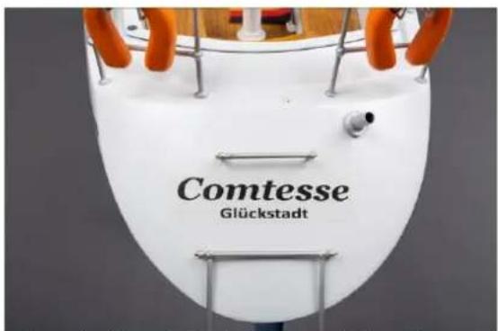
Fig. bathing ladder folded down, additional rung
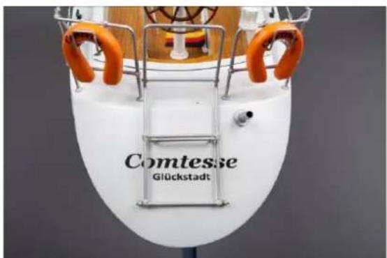
Fig. bathing ladder folded up, locked in position
Stage 11, fittings and finishing work
Steering column and steering wheel
Make the steering column with steering wheel from parts 4.2 - 4.11.
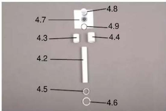
Fig. parts steering column
Slide parts 4.3 and 4.4 into each other so that a 3mm recess is made at the top to accommodate the compass rose and the compass glass. Push both parts onto the steering column 4.2 in such a way that a flush support is created on the inside. Cut out the compass rose and glue it onto the base 4.9. Glue both into the compass housing.
Slide the foot 4.5 onto the bottom of the compass column. Then push the flange 4.6 onto the bottom and glue it in place. Finally, glue in the compass glass. For this purpose Tacky Glue, order number 44085 can be used.
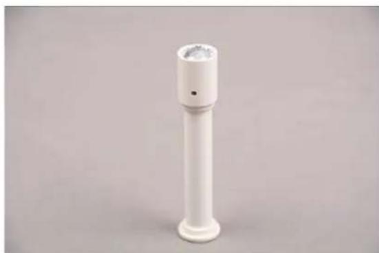
Fig. finished steering column
Glue the steering wheel 4.10 to the axle 4.11. Drill a 2mm hole in the steering column and insert the steering wheel.
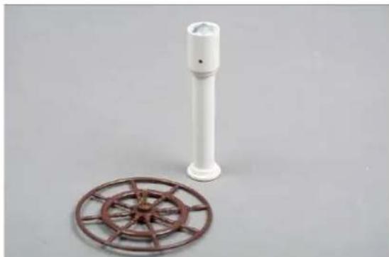
Fig. steering column and steering wheel
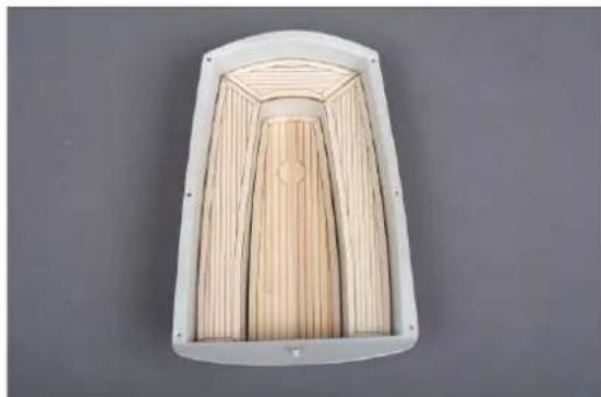
Fig. benches and floor
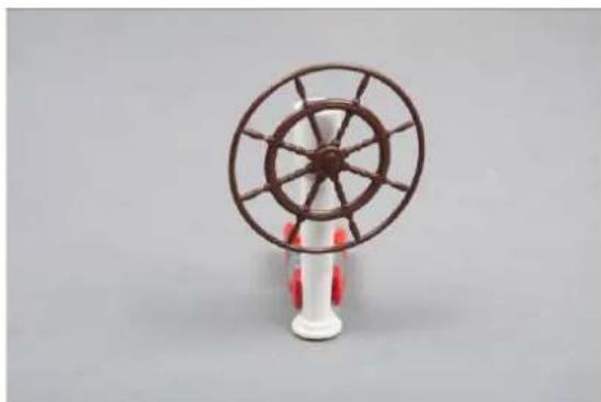
Fig. steering column with steering wheel
The next step is to install the windows, skylight and companionway.
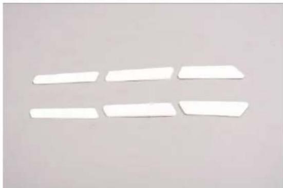
Fig. Windows
Now paint the cockpit floor and the benches part 4.21 to 4.24 several times with pore filler as primer and sand. If you want to stain the wooden parts, you must do this before the treatment with pore filler.
Cut out the windows from the decal sheet and glue them onto the ABS windows. After painting the hull, attach to the body.
The parts can then be lacquered with a colourless glossy or silk matt lacquer.
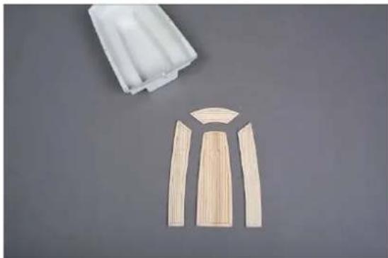
Fig. cockpit and wooden parts for cockpit

Fig. skylight
Do the same with the skylight.
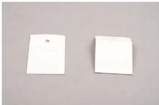
Fig. companionway
Carefully bend the companionway at the mark and adjust it to the cockpit wall. Slide the hole over the deck passage of the main sheet. Paint the companionway and stick it on after painting the cockpit.
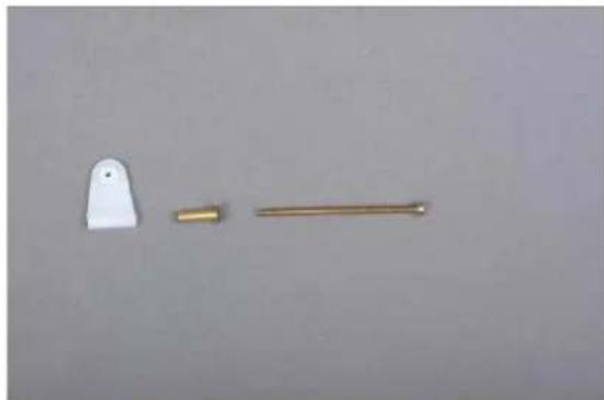
Drill a 5 mm hole in the transom for the foot of the flagpole. Glue the brass tube 11.1 at one end with 5 min. epoxy so that no water can enter the hull later. Then glue the tube into the hull.
Afterwards slide the flange 11.2 over the tube and glue it in place.
Insert the flag stick 11.4 into the foot. Attach the flag 11.3 to the flagpole.
Grind the life jackets round, paint them, apply stickers, hang them into the holders 9.17 and secure them with superglue.
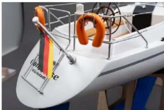
Fig. flagpole and life jackets
For the two winches from parts 11.12 glue 4 pieces each together for the pedestals. Then adjust to the cockpit slope. Varnish the bases several times with pore filler and then paint. Attach the pedestals to the hull. Drill two 1.6 mm holes and screw on the winches.
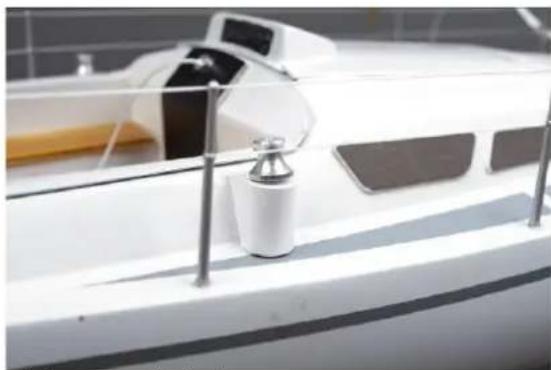
Fig. winch base and winches
Attach the cleats 11.8 to the stern, midships near the shroud tensioners and to the bow.
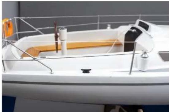
Fig. cleat rear
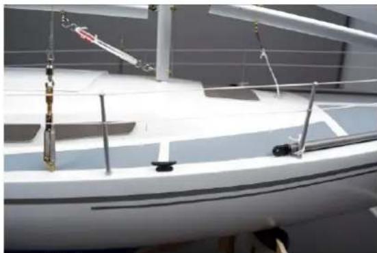
Fig. cleat midships
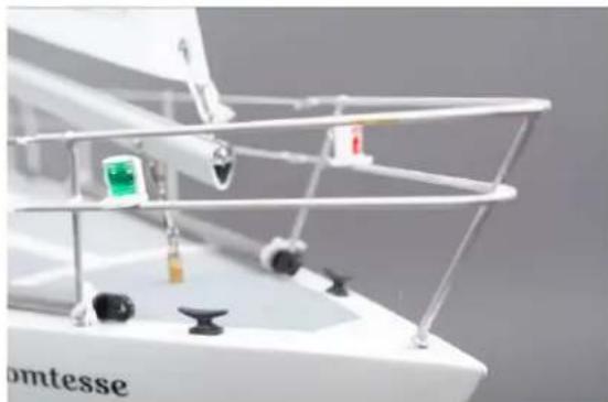
Fig. cleat bow
Put the plugs 11.10 to the spinnaker booms 11.9 and tie them to the railing with ropes.
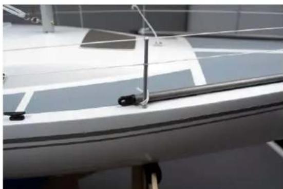
Fig. Spinnacker booms
Finally apply the decals.
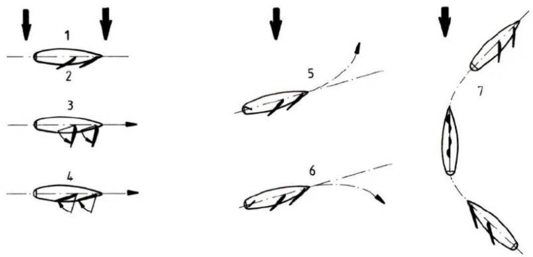
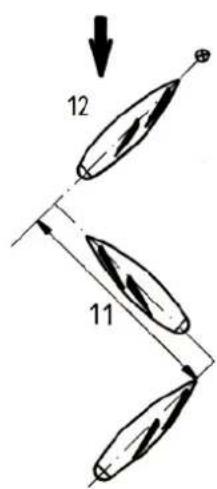
Some general basic terms of sailing, drawing "12"
-
Weather side: The side facing the wind.
-
Lee side: The side facing away from the wind.
- Slacken sail: Pay out the sheets to allow the sails to swing out.
- Close haul sail: Pull in the sheets to haul the sails in.
By opening or tightening the sheets, the sails are brought into the most favourable position to the wind with the course unchanged.
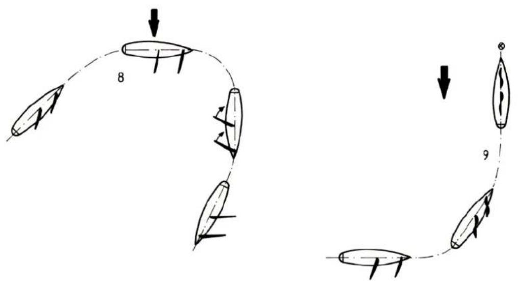
- luffing: Alter the boat's course using the rudder to bring the boat closer to the wind. This means reducing the angle between course and wind direction.
6.Bearing away: Alter the boat's course using the rudder to turn the boat away from the wind, i.e. to increase the angle between the boat's course and the wind direction. - Going about: Manoeuvre for altering course, Whereby the bow turns through the wind.
- Gybing: Manoeuvre for altering course, Whereby the stern turns through the wind.
-
Heaving to: Manoeuvre for bringing the The boat to a halt. The bow of The boat is turned into the wind, so that the sails no longer produce thrust (shivering).
-
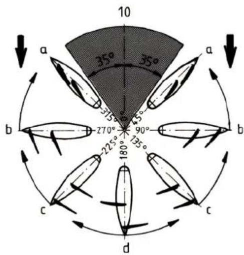
Directions:
a) Luffing. Sailing the boat at the most acute angle to the wind.
b) Sailing with wind abeam.
c) Sailing with free wind.
d) Sailing downwind.
- Beat: Straight run between two changes in direction.
- Tacking: Approach towards an upwind target point in an area which is not directly accessible, i.e. to sail towards a target point using several cross-wind beats, eventually working upwind.
The maiden run
For the first test runs seek out a fairly large, calm stretch of water, and wait for a day with constant wind, of a light to moderate strength. It is best to start from the bank towards which the wind is blowing.
Assemble the model completely.
Switch the radio control system on and set the sails to a middle position. Place the boat in the water and push it away from the bank. If you closehaul the sails the boat will turn obliquely into wind and sail away from you. The sails can now be close-hauled as far as possible. Depending on the wind strength, the Comtesse will heel (lean over); don't worry - it cannot capsize. As the boat is steered closer and closer to the wind direction, at a particular angle the sails will start to shiver (flap about). The boat is now facing into wind and will come to a halt. Both sails should start shivering at the same moment. If one sail shivers too early, tighten the corresponding sheet slightly.
When you wish to return to the bank, turn the boat and run the sails right up. The boat will now sail directly downwind. In this direction all sailing boats exhibit a lack of directional stability, because of the asymmetrical effect of the wind, and you will need to correct the course with the rudder from time to time.
To avoid damaging of the boat, practise setting off and heaving to under sail. Setting off presents no problem - you can simply give the boat a push. To heave to you have to slow the boat down, otherwise it will run into the bank at full tilt, which might cause damage. A sailing oat is braked by running the sail up fully and turning the boat into the wind. The sails will flutter and produce no more thrust.
Once you feel familiar with the boat, you will naturally want to set yourself tasks, perhaps steering towards particular points, or sailing round turn markers. When two model skippers meet, you will find that a friendly, competitive regatta atmosphere soon builds up, which will add considerably to the excitement.
Sail trimming
The sails are trimmed to optimise the boat's performance for particular conditions. By trimming we mean atterring the curvature (belly) of the sails. In a strong wind the sails are trimmed flat, while in lighter winds the sails are set with a very pronounced belly.
The belly of the jib and mainsail is altered by adjusting the screws 6.14 on the peak fittings.
There are plenty of informative books available, if you wish to study and learn more about the art of sailing.
We reserve the right to alter technical specifications.
Optional, installation of the drive set
If you would like to have an electric drive in your Comtesse, here are the installation instructions for the optional drive set, which is not included in the kit.
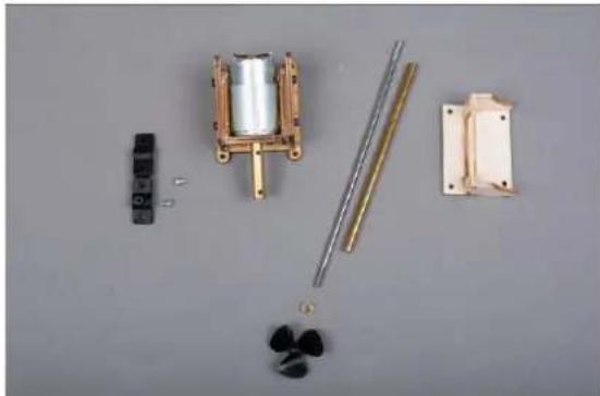
Fig. Components of the drive set
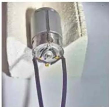
First solder the interference suppression capacitors to the motor so that both capacitors 103 (value 10 nf) run from the terminal lug to the motor housing. Grind the motor housing very well at the soldering point. Solder the third capacitor 473 (value 47 nf) between the two terminal lugs. Insulate the capacitor legs with shrink tubing.
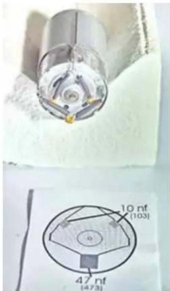
Motor interference suppression
Next solder on the connecting cables.
Assemble the engine mount.
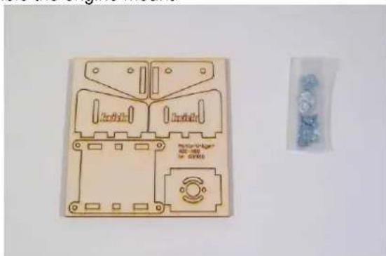
Fig. engine mount kit
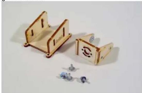
Fig. Motor mount glued
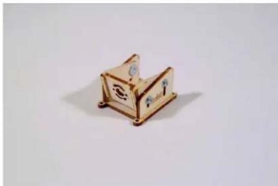
Abb Fig. Drill lubrication hole in sterntube
Now use the guide of the grease nipple and drill through the sterntube.
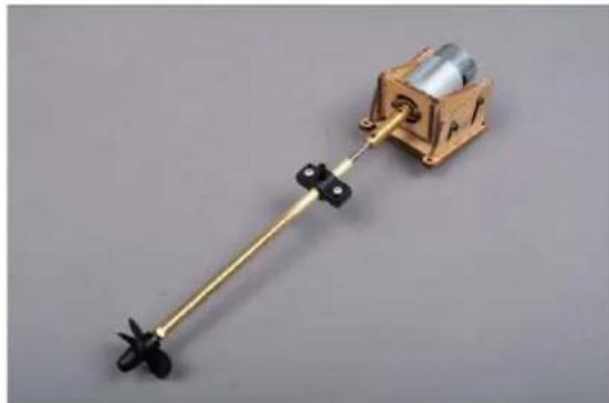
Fig. motor mount assembled
Screw the motor into the motor mount and secure the coupling with shaft to the motor.
Now make the lubrication of the shaft with the plastic lubricating nipple fixed to the stern tube.
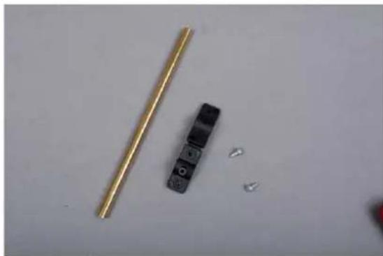
Fig. mounted drive
Slide the complete unit into the hull and align it. It is important to ensure that the complete unit runs smoothly without force. Align the adjustable motor mount and tighten the screws. If smooth running is guaranteed, the gluing can be started. Use Stabilit Express for this purpose. First glue the sterntube into the hull. After the adhesive has cured, check the smooth running again and then glue the engine mount with Stabilit Express.
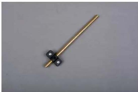
Fig. lubrication nipple
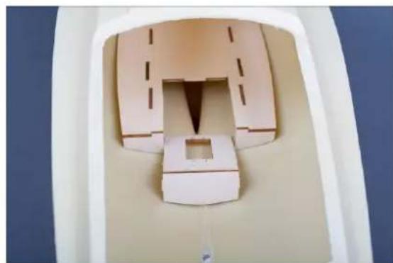
Fig. separating for the drive
Fig. lubrication nipple with sterntube
Cut out the servo area on the RC board at the markings.
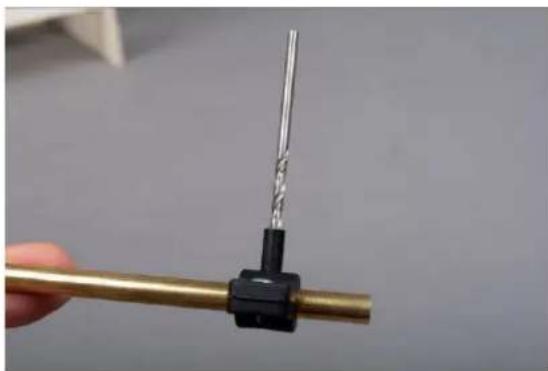
Screw on the lubrication nipple 15mm before the end of the sterntube and fix it on the sterntube with superglue.
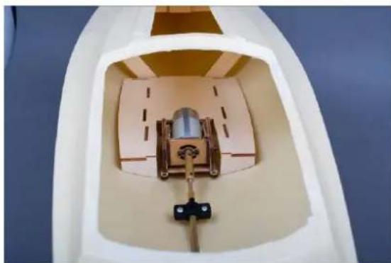
Fig. Placing the drive in the hull
Now place the complete propulsion unit in the hull and align it.
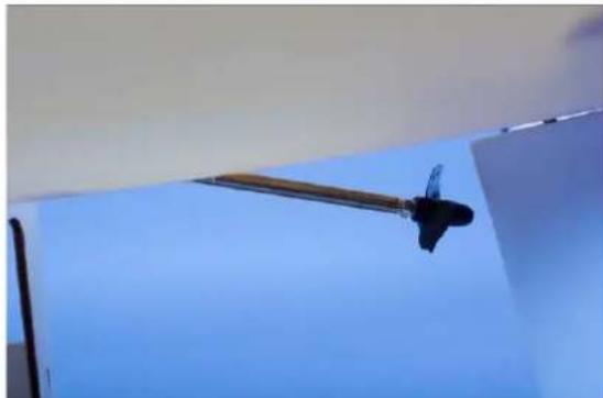
Fig. drive
Finally glue in the RC board.
At the position of the motor the servo was removed before. Therefore now a new mounting for the servo must be placed.
Now the installation of the drive is finished.
Now the bracket and the rudder servo can be installed.
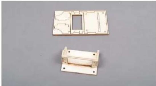
Fig. laser board and finished servo mount
Place the servo in the bracket and position both on the side of the RC board. Fasten the bracket to the RC board with 2 screws A-16.
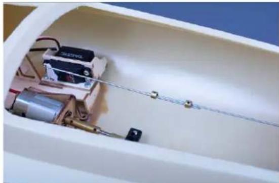
Fig. servo mount with servo
Hook in parts 2.7 and 3.12 and connect them with the two set collars.
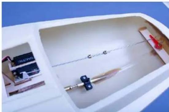
Fig. connection servo and rudder
Parts list Comtesse
Parts with the note "BS" are included in the fitting set, order no. ro1073. Parts with the note "AS" are included in the drive set, order no. ro1074.
| No. | Description | Material | Dimensions mm | Note | Qty. |
| Stage 0 Stand | |||||
| 0.1 | Side | Plywood | 5 mm | Lasersheet 1 | 1 |
| 0.2 | Right side | Plywood | 5 mm | Lasersheet 1 | 1 |
| 0.3 | Connection | Plywood | 5 mm | Lasersheet 1 | 2 |
| Stage 1 Hull | |||||
| 1.1 | Hull | ABS | Prefab | 1 | |
| 1.2 | Reinforcement board | Plywood | 3 mm | Lasersheet 2 | 1 |
| 1.3 | Nut support | Plywood | 3 mm | Lasersheet 2 | 1 |
| 1.4 | Cover disc | Plywood | 3 mm | Lasersheet 2 | 1 |
| 1.5 | Hex nut | Metal | M 3 | Bag 1 | 1 |
| 1.6 | Eyebolt | Metal | M 3 | Bag 1 | 1 |
| 1.7 | Frame | Plywood | 3 mm | Lasersheet 2 | 1 |
| 1.8 | Doubling | Plywood | 3 mm | Lasersheet 2 | 1 |
| 1.9 | Cover | Plywood | 3 mm | Lasersheet 2 | 2 |
| 1.10 | Reinforcement board | Plywood | 3 mm | Lasersheet 2 | 2 |
| 1.11 | Nut support | Plywood | 3 mm | Lasersheet 2 | 2 |
| 1.12 | Cover disc | Plywood | 3 mm | Lasersheet 2 | 2 |
| 1.13 | Hex nut | Metal | M 3 | Bag 1 | 2 |
| 1.14 | Eyebolt | Metal | M 3 | Bag 1 | 2 |
| 1.15 | Hull reinforcement | ABS | 1,5 mm | Lasersheet 3 | 1 |
| Stage 2 Rudder | |||||
| 2.1 | Rudder bearing | Brass | Ø 4 x Ø 5 x 30 | Bag 1 | 1 |
| 2.2 | Rudder support | Plywood | 4 mm | Lasersheet 2 | 1 |
| 2.3 | Rudder | Plastic/brass | Prefab | 1 | |
| 2.4 | Rudder lever | Plastic | Prefab | Bag 1 | 1 |
| 2.5 | Collar | Metal | Ø 4 x Ø 7 x 5 | Bag 1 | 1 |
| 2.6 | Hex screw | Metal | M3 x 10 | Bag 1 | 1 |
| 2.7 | Rudder linkage | Steel | Ø 1,5 x 200 | Bag 2 | 1 |
| Stage 3 RC-Installation | |||||
| 3.1 | Ballast | Iron shot | 1,8 kg | Not contained | |
| 3.4 | RC mounting plate | Plywood | 3 mm | Lasersheet 2 | 1 |
| 3.5 | Reinforcement | Plywood | 3 mm | Lasersheet 2 | 1 |
| 3.6 | Longitudinal reinforcement | Plywood | 3 mm | Lasersheet 2 | 2 |
| 3.7 | Support | Plywood | 3 mm | Lasersheet 2 | 1 |
| 3.8 | Winch plate | Plywood | 3 mm | Lasersheet 2 | 1 |
| 3.9 | Post | Plywood | 3 mm | Lasersheet 2 | 2 |
| 3.10 | Support | Plywood | 3 mm | Lasersheet 2 | 2 |
| 3.11 | Brace | Plywood | 3 mm | Lasersheet 2 | 2 |
| 3.12 | Screw | Steel | Ø 2,2 x 6,5 | Bag 1 | 4 |
| 3.12 | Steering linkage | Steel | Ø 1,5 x 200 | Bag 2 | 1 |
| 3.13 | Grub screw | Steel | M3 x 3 | Bag 1 | 2 |
| 3.14 | Collar | Steel | Ø 3 innen | Bag 1 | 2 |
| Stage 4 Cockpit | |||||
| 4.1 | Cockpit | ABS | Vac forming | 1 | |
| 4.2 | Steering column | ABS | Ø 10 x 70 | BS Bag 1 | 1 |
| 4.3 | Spacer ring | ABS | Ø 12 x 15 | BS Bag 1 | 1 |
| 4.4 | Compass housing | ABS | Ø 14 x 18 | BS Bag 1 | 1 |
| 4.5 | Foot | ABS | Ø 12 x 5 | BS Bag 1 | 1 |
| 4.6 | Flange | ABS | 1,5 mm | Lasersheet 3 | 1 |
| 4.7 | Compass rose | Paper | Plan 1 | 1 | |
| 4.8 | Compass glass | Glass | Prefab | BS Bag 1 | 1 |
| 4.9 | Underlay | ABS | 1,5 mm | Lasersheet 3 | 1 |
| 4.10 | Steering wheel | Plastic | Injection moulded | BS Bag 1 | 1 |
| 4.11 | Axle | Brass | Ø 2 x 15 | BS Bag 1 | 1 |
| 4.12 | Sheet feedthrough | Brass | Ø 4 x 8 | Bag 3 | 2 |
| 4.13 | Rivet | Brass | Prefab | Bag 3 | 4 |
| 4.14 | Stop sleeve | Brass | Ø 5 x 3 | Bag 3 | 2 |
| 4.15 | Sliding hatch | ABS | Tiefzieheit | 1 | |
| 4.16 | Frame | ABS | 1,5 mm | Lasersheet 3 | 1 |
| 4.17 | Skylight | ABS | 1,5 mm | Lasersheet 3 | 1 |
| 4.18 | Companionway | ABS | 1,5 mm | Lasersheet 3 | 1 |
| 4.19 | Superstructure windows 3 pcs. | ABS | 1,5 mm | Lasersheet 3 | 2 |
| 4.20 | Mastfoot | Brass | Ø 6 x 5 x 16 | Bag 3 | 1 |
| 4.21 | Bench left | Plywood | 3 mm | Lasersheet 2 | 1 |
| 4.22 | Bench right | Plywood | 3 mm | Lasersheet 2 | 1 |
| 4.23 | Central bench | Plywood | 3 mm | Lasersheet 2 | 1 |
| 4.24 | Cockpit floor | Plywood | 3 mm | Lasersheet 2 | 1 |
| 4.25 | Countersunk screw | Steel | 2,2 x 6,5 | Bag 3 | 6 |
| Stage 5 Mast | |||||
| 5.1 | Mast | Alu | Prefab 1190mm lg | bundle 1 | 1 |
| 5.2 | Pin | Brass | Ø 4 x 40 | Bag 4 | 1 |
| 5.3 | S-Hook | Metal | Prefab | Bag 4 | 1 |
| 5.4 | Eyebolt | Metal | M2 x 20 | Bag 4 | 1 |
| 5.5 | Nut | Metal | M2 x 20 | Bag 4 | 2 |
| 5.6 | Bracket | Brass | 1 x 5 x 25 | Bag 4 | 1 |
| 5.7 | Eyebolt | Metal | M 2,5 x 40 | Bag 4 | 1 |
| 5.8 | Nut | Metal | M 2,5 | Bag 4 | 1 |
| 5.9 | Shrouds | Steel cable | Ø 0,5 x 2200 | Bag 7 | 1 |
| 5.10 | Crimp sleeve | Prefab | Bag 4 | 1 | |
| 5.11 | Lamp support | Alu | 0.5 x 5 x30 | Bag 4 | 1 |
| 5.12 | Yacht lamp | Plastic | Prefab | BS Bag 1 | 1 |
| 5.13 | Bracket | Alu | 0,5 x 5 x 30 | Bag 4 | 1 |
| 5.14 | Self tapping screw | Steel | Ø 2,3 x 6,5 | Bag 4 | 2 |
| 5.15 | Flange sleeve | Brass | Ø 5 x 7 | Bag 4 | 1 |
| 5.16 | Screw | Brass | M 2 x 25 | Bag 4 | 1 |
| 5.17 | Top fitting | Plastic | Injection moulded | Bag 4 | 1 |
| 5.18 | Clevis | Steel | Prefab | Bag 4 | 2 |
| 5.19 | Eyebolt | Brass | M 3 | Bag 4 | 2 |
| 5.20 | Swivel | Steel | Prefab | Bag 4 | 2 |
| 5.21 | Crimp sleeve | Prefab | Bag 4 | 2 | |
| Stage 6 Main- and Foresailboom | |||||
| 6.1 | Main Boom | Alu | 285 mm long | Bag 2 | 1 |
| 6.2 | Eyebolt | Brass | M 2 x 20 | Bag 5 | 2 |
| 6.3 | Nut | Brass | M2 | Bag 5 | 2 |
| 6.4 | Nut | Brass | M2 | Bag 5 | 2 |
| 6.5 | S-Hook | Steel | Prefab | Bag 5 | 1 |
| 6.6 | Foresail Boom | Alu | 310 mm lang | Bag 2 | 1 |
| 6.7 | Eyebolt | Brass | M 2 x 20 | Bag 5 | 1 |
| 6.8 | Nut | Brass | M2 | Bag 5 | 1 |
| 6.9 | Nut | Brass | M2 | Bag 5 | 1 |
| 6.10 | Swivel | Steel | Prefab | Bag 5 | 1 |
| 6.11 | Screw | Brass | M 2 x 10 | Bag 5 | 1 |
| 6.12 | Nut | Brass | M 2 | Bag 5 | 1 |
| 6.13 | S-Hook | Steel | Prefab | Bag 5 | 1 |
| 6.14 | Flange sleeve | Brass | Ø 5 x 7 | Bag 5 | 2 |
| 6.15 | Screw | Brass | M 2 x 40 | Bag 5 | 2 |
| 6.16 | Boom Fitting | Plastic | Injection moulded | Bag 5 | 2 |
| 6.17 | Carbine | Prefab | Bag 5 | 3 | |
| Stage 7 Mainsail | |||||
| 7.1 | Reinforcing tape | Sail tape | b 20 x 1100 | Bag 8 | 1 |
| 7.2 | Reinforcing tape | Sail tape | b 30 x 140 | Bag 8 | 1 |
| 7.3 | Sail slides | Plastic | Ø 3 x 2 x 150 | Bag 8 | 1 |
| 7.4 | Mainsail | Sailcloth | Prefab | Rolle | 1 |
| 7.5 | Rivet | Metal | Ø 3 x 3,5 | Bag 6 | 3 |
| 7.6 | Washer | Metal | Ø 3,2 | Bag 6 | 6 |
| 7.7 | Cord | Takelgarn | Ø 1 | Bag 7 | 2 |
| 7.8 | Hold-down | Takelgarn | Ø 1 x 300 | Bag 7 | 1 |
| 7.9 | Line tensioner | Plastic | Injection moulded | Bag 6 | 1 |
| 7.10 | Punch | Brass | Ø 3 x 30 | Bag 7 | 1 |
| Stage 8 Foresail | |||||
| 8.1 | Luff cable | Steel cable | Ø 0,5 x 1100 | Bag 7 | 1 |
| 8.2 | Crimp sleeve | Metal | Prefab | Bag 6 | 2 |
| 8.3 | S-Hook | Metal | Prefab | Bag 6 | 2 |
| 8.4 | Foresail | Sailcloth | Prefab | Rolle | 1 |
| 8.5 | Sail tape | dbl. sided | 1000 lg | Bag 8 | 1 |
| 8.6 | Reinforcing tape | Sail tape | b 30 x 140 | Bag 8 | 1 |
| 8.7 | Rivet | Metal | Ø 3 x 3,5 | Bag 6 | 3 |
| 8.8 | Washer | Metal | Ø 3,2 | Bag 6 | 6 |
| 8.10 | Cord | Rigging yarn | Ø 1 | Bag 7 | 2 |
| 8.11 | Leech cord | Rigging yarn | Ø 1 x 400 | Bag 7 | 1 |
| 8.12 | Crimp sleeve | Metal | Prefab | Bag 6 | 2 |
| 8.13 | Foresheet | Rigging yarn | Ø 1 x 600 | Bag 7 | 1 |
| 8.14 | Main sheet | Rigging yarn | Ø 1 x 800 | Bag 7 | 1 |
| Stage 9 Bow pulpit / Stern pulpit | |||||
| 9.1 | Bow pulpit top | Brass tube | Ø 2 see plan | 240 lg. Bd. 1 | 1 |
| 9.2 | Bow pulpit bottom | Brass tube | Ø 2 see plan | 240 lg. Bd. 1 | 1 |
| 9.3 | Rail stanchion front | Brass tube | Ø 2 see plan | 60 lg. Bd. 1 | 1 |
| 9.4 | Rail stanchion rear | Brass tube | Ø 2 see plan | 65 lg. Bd. 1 | 2 |
| 9.5 | Washer | Metal | Ø 2,2 inner | BS Bag 2 | 3 |
| 9.6 | Split pin | Metal | Ø 1 x 15 | BS Bag 2 | 3 |
| 9.7 | Lamp body | plastic | Ø 7 x 9,5 | BS Bag 1 | 2 |
| 9.8 | Lamp support | ABS | Laserteil | Lasersheet 3 | 2 |
| 9.9 | Split pin | Metal | Ø 1 x 15 | BS Bag 2 | 4 |
| 9.10 | rail above right for stern pulpit | Brass tube | Ø 2 see plan | 210 lg. Bd. 1 | 1 |
| 9.11 | rail above left for stern pulpit | Brass tube | Ø 2 see plan | 210 lg. Bd. 1 | 1 |
| 9.12 | Rail bottom | Brass tube | Ø 2 see plan | 80 lg. Bd. 1 | 2 |
| 9.13 | Rail stanchion for stern pulpit | Brass tube | Ø 2 see plan | 55 lg. Bd. 1 | 2 |
| 9.14 | Washer | Metal | Ø 2,2 inner | BS Bag 2 | 6 |
| 9.15 | Split pin | Metal | Ø 1 x 15 | BS Bag 2 | 6 |
| 9.16 | Split pin | Metal | Ø 1 x 15 | BS Bag 2 | 4 |
| 9.17 | Holder for life jacket | Brass | Ø 1 see plan | 95 lg. Bag 9 | 2 |
| 9.18 | Lamp body | Plastic | Ø 7 x 9,5 | BS Bag 1 | 1 |
| 9.19 | Lamp support | ABS | Laser part | Lasersheet 3 | 1 |
| Stage 10 Rail / Bathing ladder | |||||
| 10.1 | Stanchion | Brass | Prefab | BS Bag 2 | 10 |
| 10.2 | Rail | Steel wire | Ø 0,5 x 1000 | BS Bag 3 | 4 |
| 10.3 | crimp sleeve | Metal | Prefab | BS Bag 3 | 8 |
| 10.4 | bathing ladder bracket | Brass tube | Ø 2 nach Plan | 245 lg. Bd. 1 | 1 |
| 10.5 | Split pin | Metal | Ø 1 x 15 | BS Bag 2 | 6 |
| 10.6 | Rung | Brass tube | Ø 2 see plan | 37 lg. Bd. 1 | 2 |
| 10.7 | Bottom rung | Brass tube | Ø 2 see plan | 37 lg. Bd. 1 | 1 |
| 10.8 | rotation axle | Brass | Ø 1 x 46 | Bag 9 | 1 |
| 10.9 | Split pin | Metal | Ø 1 x 15 | BS Bag 2 | 2 |
| 10.10 | Axle | Brass | Ø 1 nach Plan | Bag 9 | 1 |
| 10.11 | Rung | Brass tube | Ø 2 x 32 | 32 lg. Bd. 1 | 1 |
| Stage 11 Fittings | |||||
| 11.1 | Foot for flagpole | Brass tube | Ø 5 x Ø 4 x 20 | BS Bag 4 | 1 |
| 11.2 | Flange | ABS | Laser part | Lasersheet 3 | 1 |
| 11.3 | Flagg | Fabric | Prefab | BS Bag 4 | 1 |
| 11.4 | Flagpole | Plastic | Prefab | BS Bag 4 | 1 |
| 11.5 | Life jacket | Plastic | Prefab | BS Bag 4 | 2 |
| 11.6 | Winch drum | Alu | Ø 12 x 10 | BS Bag 4 | 2 |
| 11.7 | Screw | Steel | M2 x 20 | BS Bag 4 | 2 |
| 11.8 | Cleat | Plastic | Injection moulded | BS Bag 4 | 6 |
| 11.9 | Spinnacker boom | Alu | Ø 6x0,5 x 248 | Bd. 1 | 2 |
| 11.10 | Plug | Plastic | Injection moulded | BS Bag 4 | 4 |
| 11.11 | Cord | Yarn | Ø 1 x 100 | Bag 7 | 4 |
| 11.12 | Winch support | Plywood | Laser part | Lasersheet 1 | 8 |
| Parts List Drive Gear | |||||
| A-1 | Motor | Prefab | AS Bag 1 | 1 | |
| A-2 | Suppression set | Prefab | AS Bag 1 | 1 | |
| A-3 | Motor mount | Laser part | AS Bag 1 | 1 | |
| A-4 | Screw | Metal | M3 x 10 | AS Bag 1 | 4 |
| A-5 | Drive nut | Metal | M3 | AS Bag 1 | 4 |
| A-6 | Washer | Metal | M3 | AS Bag 1 | 4 |
| A-7 | Stern tube | Steel | Ø 6 x Ø 4 x 135 | AS Bag 1 | 1 |
| A-8 | Shaft | Steel | Ø 4 x 175 | AS Bag 1 | 1 |
| A-9 | Locking nut | Brass | M 4 | AS Bag 1 | 1 |
| A-10 | Propeller | Plastic | Ø 35 mm | AS Bag 1 | 1 |
| A-11 | Coupling | Brass | Prefab | AS Bag 1 | 1 |
| A-12 | Grub Screw | Steel | M 3 x 3 | AS Bag 1 | 4 |
| A-13 | Lubricating nipple | Plastic | Prefab | AS Bag 1 | 1 |
| A-14 | Screw | Steel | M 2,5 x 8 | AS Bag 1 | 2 |
| A-15 | Servo mount | Laser part | AS Bag 1 | 1 | |
| A-16 | Screw | Steel | Ø 2,9 x 9,5 | AS Bag 1 | 2 |
| A-17 | Screw | Steel | Ø 2,9 x 6,5 | AS Bag 1 | 2 |
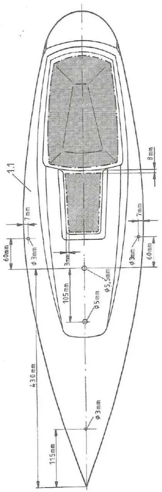
Fig. 1 A Drill holes in deck
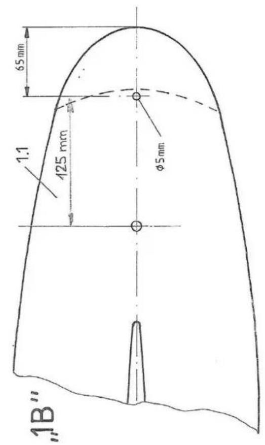
Fig. 1B Hull underside
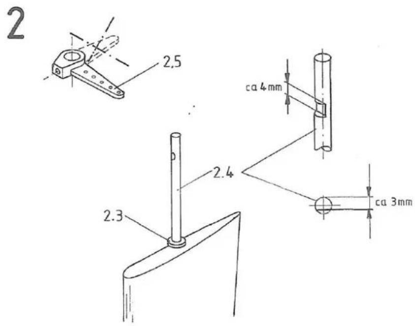
Fig.2 Rudder
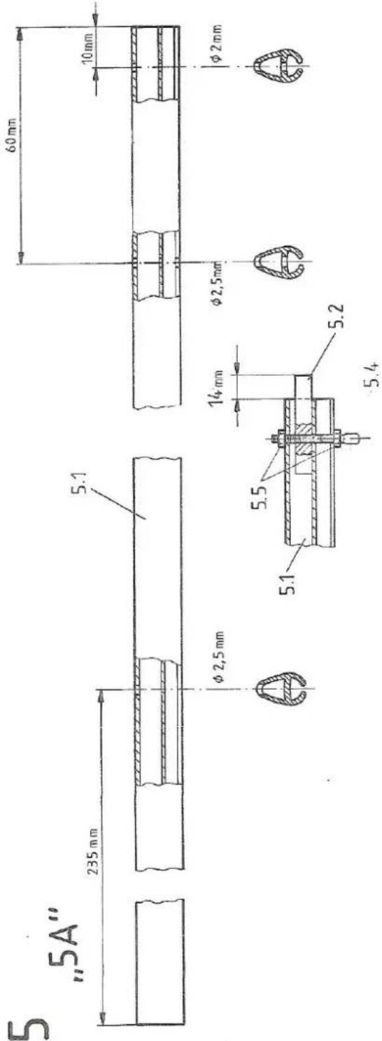
Fig. 5 Mast
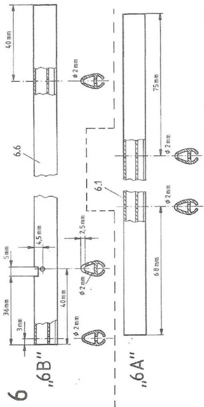
Fig. 6 Booms
12
krick
Vue: couple principal assemble
Vue: supports colles

Vue: support de treuil complet