DW6KR7071BB - Dishwasher SAMSUNG - Free user manual and instructions
Find the device manual for free DW6KR7071BB SAMSUNG in PDF.

User questions about DW6KR7071BB SAMSUNG
0 question about this device. Answer the ones you know or ask your own.
Ask a new question about this device
Download the instructions for your Dishwasher in PDF format for free! Find your manual DW6KR7071BB - SAMSUNG and take your electronic device back in hand. On this page are published all the documents necessary for the use of your device. DW6KR7071BB by SAMSUNG.
USER MANUAL DW6KR7071BB SAMSUNG
Serie DW6*R707*/DW6*R705*/DW6*R704*

text_image
SAMSUNGInhalt
natural_image
Symbol of a trash bin crossed with no text or symbols, representing waste sorting or disposal (no text present)natural_image
Line drawing of a kitchen sink with a circular inset showing a dial indicator (no text or symbols)
natural_image
Technical line drawing of a kitchen sink and adjacent appliances, showing internal components and wiring (no text or symbols)natural_image
Line drawing of a hand holding a smartphone against a wall-mounted shelf (no text or symbols)natural_image
Technical diagram showing a structural component with an arrow indicating rotation, and a magnified inset of a bracket detail (no text or symbols)text_image
Diagram illustrating a kitchen ventilation system with labeled components and airflow direction arrowstext_image
Diagram showing a screwdriver inserted into a base plate with labeled components C, D, and others.
text_image
A F 30 mm C E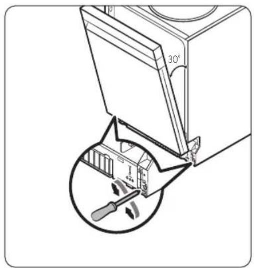
text_image
30°natural_image
Diagram of screwdriver installation on a flatbed electronic device (no text or symbols)natural_image
Technical diagram showing screwdriver installation with downward arrows indicating assembly or repair (no text or symbols present)natural_image
Technical diagram showing a structural component with an inset magnified view of layered materials (no text or symbols)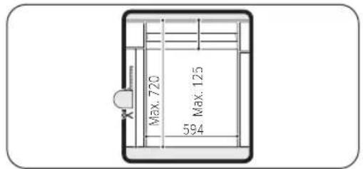
text_image
Max. 720 594 Max. 125
text_image
Diagram illustrating a device with labeled components and directional arrows, likely illustrating a process or assembly.natural_image
Technical line drawing of a refrigerator with a door and side panel, showing internal components and airflow direction (no text or symbols)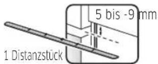
natural_image
Technical line drawing of a door frame assembly with no visible text or symbols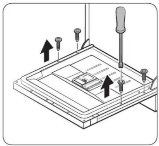
natural_image
Technical diagram of a mechanical assembly with screwdrivers and a base plate, showing upward force arrows (no text or symbols)natural_image
Technical diagram showing screwdriver installation on a device with arrows indicating downward motion (no text or symbols present)natural_image
Line drawing of an open refrigerator with internal compartments and a hand inserting a cable (no text or symbols)natural_image
Illustration of a hand using a tool to adjust or install a metal bracket, with an inset showing the same component (no text or symbols present)natural_image
Line drawing of an open refrigerator with internal compartments and storage racks (no text or symbols)text_image
Diagram illustrating screwdriver tool positioning a mechanical component with directional arrows and magnified view of the component.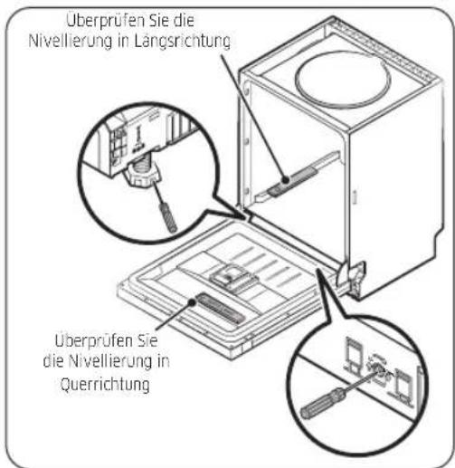
natural_image
Diagram showing two views of a car interior with a magnified inset highlighting the curved arm (no text or symbols present)natural_image
Pure technical line drawing of a structural joint or bracket (no text or symbols)natural_image
Technical diagram showing a mechanical bracket assembly with an arrow indicating direction (no text or symbols present)text_image
Diagram showing a mechanical or structural component with labeled parts and directional arrows indicating movement or force.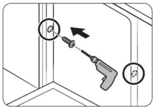
text_image
Diagram showing a screwdriver inserted into a corner with a magnified inset, illustrating the process of tool application.
text_image
Diagram showing a mechanical or structural component with two circular insets highlighting features, one with an arrow pointing to a circular feature.VORSICHT
natural_image
Diagram showing a panel being inserted into a metal sheet, with an inset magnified view of the cutting edge detail (no text or symbols present)natural_image
Diagram showing a hand using a saw to cut through a metal frame (no text or symbols present)natural_image
Diagram showing a structural joint with an arrow indicating direction (no text or symbols present)text_image
Diagram showing electrical wiring connections with labeled components and directional arrows, including a magnified inset of a mechanical component.
text_image
545,4
natural_image
Diagram showing a black arrow pointing to a gray rectangular block on a diagonal line, with no text or symbols present.text_image
Diagram showing electrical connections with labeled components and a magnified view of a mechanical component.text_image
Diagram showing cable installation with labeled components and a magnified inset highlighting a mechanical component.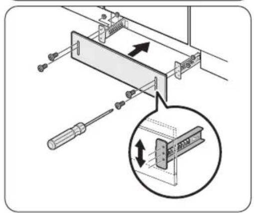
text_image
Technical diagram showing a mechanical assembly with screwdriver and directional arrows, including a magnified inset of a component detail.Deutsch 37
natural_image
Diagram of a refrigerator internal structure with an inset showing a mechanical component (no text or symbols)natural_image
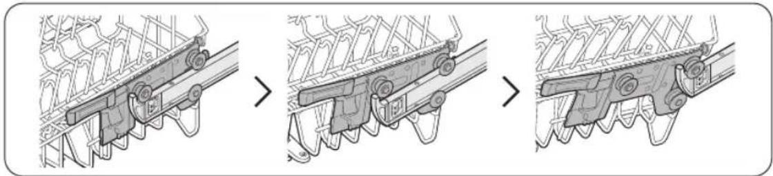
Three-step diagram showing mechanical assembly with no visible text or symbolsDeutsch
Modelle DW6*R707*/DW6*R705* Modelle DW6*R704*
HINWEIS
text_image
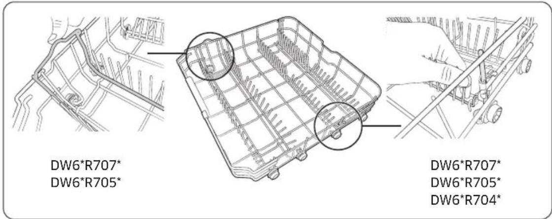
DW6*R707* DW6*R705* DW6*R707* DW6*R705* DW6*R704*Oberkorb
natural_image
Technical line drawing of a mechanical component with multiple circular features and grid lines (no text or symbols)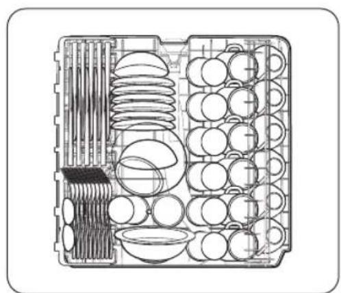
natural_image
Technical line drawing of a multi-compartment kitchen or storage unit with cutlery and circular components (no text or labels)Modelle DW6*R707*/DW6*R705* Modelle DW6*R704*
Deutsch 43

natural_image
Technical diagram of a heat exchanger or cooling unit with internal wavy patterns and no visible text or symbolsnatural_image
Technical line drawing of a mechanical assembly with cylindrical components and mounting brackets (no text or symbols)natural_image
Hand inserting a device into a plastic case with a black arrow indicating the component (no text or symbols present)natural_image
Line drawing of a device being placed into a tray with a lid (no text or symbols)natural_image
Isometric technical diagram of a mechanical component with an arrow indicating direction (no text or symbols)natural_image
Illustration of a hand pouring liquid onto a flat surface with a small inset device (no text or symbols)natural_image
Illustration of a hand inserting a device into a folder with an arrow indicating rotation (no text or symbols)natural_image
Illustration of a bottle pouring liquid into a tray with a small inset showing a droplet (no text or symbols)natural_image
Diagram of a mechanical device with a black arrow indicating a component, no text or symbols presentnatural_image
Diagram showing a gear mechanism interacting with a mechanical component (no text or symbols)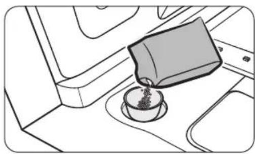
natural_image
Line drawing of a coffee cup pouring liquid into a container on an airplane (no text or symbols)
natural_image
Diagram of a mechanical device with a gear and curved arrow indicating rotation (no text or symbols)Modelle DW6*R707*, DW6*R705*
text_image
POWER 01020403050608 ECO 55° 60° 65° 60° 8:88 START Cancel & Drain (Start) 07Modelle DW6*R704*
text_image
POWER 01020403050608 ECO (5sec) 8:88 START 07 Control & Drain (5sec)Modelle DW6*R707*, DW6*R705*
text_image
AUTO 45°-65° | ECO | 60° | 65° | 40° | 60° | 0708 010203040506Modelle DW6*R704*
text_image
AUTO 45°-65° | ECO | 60° | 65° | 40° | 60° | 07 010203040506natural_image
Diagram of a refrigerator interior showing the exterior wall and side arm, with an inset circular view highlighting a mechanical component (no text or symbols present)Unterer Sprüharm
natural_image
Mechanical assembly diagram showing a rotating component with a ruler and gear (no text or symbols)natural_image
Technical illustration of a mechanical component with a central cylindrical housing and surrounding components (no text or symbols)natural_image
Diagram of a mechanical component with a circular housing and directional arrow, no text or symbols present
natural_image
Diagram of a mechanical component with a cylindrical base and a circular housing, showing a downward arrow indicating rotation (no text or symbols present)Deutsch 61
Wartung und Pflege

natural_image
Line drawing of a sink with two fixtures, one cylindrical and one threaded, no text or symbols present
natural_image
Line drawing of a sink with a hand mixer and faucet, no text or symbols present
natural_image
Diagram of a mechanical component with a rotating arrow indicating rotation (no text or symbols)natural_image
Technical line drawing of a mechanical component with multiple circular holes and a central oval feature (no text or symbols)Unterkorb
natural_image
Cross-sectional diagram of a mechanical assembly with multiple threaded components (no text or labels)BesteckkorbOberkorb

text_image
Technical diagram of a layered structure with numbered components and directional arrows indicating flow or movement.
natural_image
Technical line drawing of a mechanical assembly with gears and housing (no text or symbols)Unterkorb

natural_image
Cross-sectional technical drawing of a mechanical assembly (no visible text or labels)BesteckkorbOberkorb
text_image
Diagram of a cell membrane with labeled organelles and numbered cells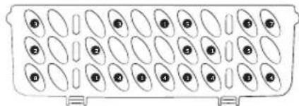
text_image
Diagram showing a grid of oval cells with numbered labels inside, likely representing a cell division or arrangement.
Séries DW6*R707*/DW6*R705*/DW6*R704*

text_image
SAMSUNGTable des matières
natural_image
Symbol of a trash bin crossed with no text or symbols, representing waste sorting or disposal (no text present)natural_image
Line drawing of a kitchen sink with a circular inset showing a dial indicator (no text or symbols)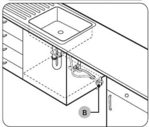
natural_image
Technical line drawing of a kitchen sink and adjacent appliances, showing internal components and wiring (no text or symbols)natural_image
Line drawing of a hand holding a smartphone against a wall-mounted shelf (no text or symbols)natural_image
Technical diagram showing a structural component with an arrow indicating rotation, and a magnified inset of a bracket detail (no text or symbols)text_image
Diagram illustrating a kitchen ventilation system with labeled components and airflow direction arrowstext_image
Diagram showing a screwdriver inserted into a workbench with labeled components C, D, and others for assembly or repair.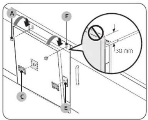
text_image
A F 30 mm C E
text_image
30°natural_image
Diagram of screwdriver installation on a flatbed electronic device (no text or symbols)natural_image
Technical diagram showing screwdriver installation with downward arrows indicating assembly or repair (no text or symbols present)natural_image
Technical diagram showing a window or panel installation with a magnified inset highlighting a specific section (no text or symbols present)
text_image
720 maximum 125 max 594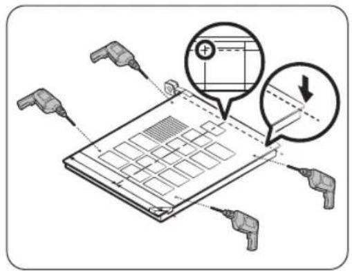
text_image
Diagram illustrating a device with labeled components and directional arrows, likely illustrating a process or assembly.natural_image
Technical line drawing of a refrigerant oven with airflow indicators (no text or symbols)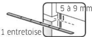
natural_image
Technical line drawing of a door frame assembly with no visible text or symbols
natural_image
Technical diagram of a mechanical assembly with screwdrivers and a base plate, showing upward force arrows (no text or symbols)natural_image
Technical diagram showing screwdriver installation on a device with arrows indicating downward motion (no text or symbols present)natural_image
Line drawing of an open refrigerator with internal compartments and a hand inserting a cable (no text or symbols)natural_image
Illustration of a hand using a tool to adjust a metal bracket, with an inset showing the detail of the component (no text or symbols present)natural_image
Line drawing of an open refrigerator with internal compartments and storage racks (no text or symbols)text_image
Diagram illustrating a screwdriver tool interacting with a mounted device, with an inset showing a 3D coordinate system.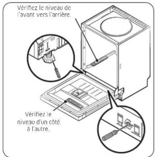
text_image
Minimum (5 mm)
natural_image
Diagram showing two views of a car interior with arrows indicating movement or change, no text or symbols present.natural_image
Pure technical line drawing of a structural joint or bracket (no text or symbols)natural_image
Technical diagram showing a mechanical bracket assembly with an arrow indicating direction (no text or symbols present)text_image
Technical diagram showing a screwdriver inserted into a bracket with a magnified inset labeled Ø2 and Ø1, likely illustrating a mechanical or electrical setup.text_image
Diagram showing a mechanical or structural component with labeled parts and directional arrows indicating movement or force.
text_image
Diagram showing a screwdriver inserted into a corner with a magnified inset, illustrating the process of tool application.
text_image
Diagram showing a mechanical or structural component with two circular insets highlighting features, one with an arrow pointing to a circular feature.ATTENTION
natural_image
Diagram showing a panel being inserted into a metal sheet, with an inset magnified view of the cutting edge detail (no text or symbols present)natural_image
Diagram showing a hand using a saw to cut through a metal frame (no text or symbols present)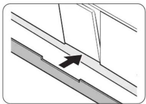
natural_image
Diagram showing a structural joint with an arrow indicating direction, no text or symbols presenttext_image
Diagram showing electrical wiring connections with labeled components and directional arrows, including a magnified inset of a mechanical component.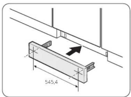
text_image
545,4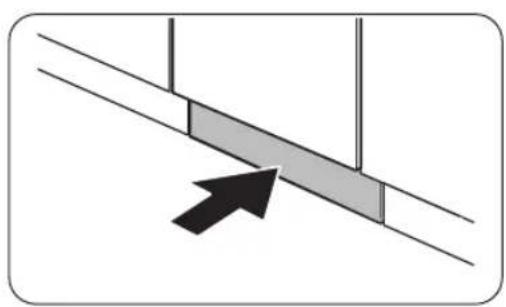
natural_image
Diagram showing a black arrow pointing to a gray rectangular block on a diagonal line, with no text or symbols present.text_image
Diagram showing mechanical assembly with labeled components and directional arrows, including a magnified inset of a tool mechanism.text_image
Diagram showing cable installation with labeled connectors and a magnified view of a mechanical component with a 120mm thickness.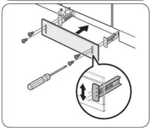
text_image
Technical diagram showing a mechanical assembly with screwdriver and directional arrows indicating movement or assembly.Avant de commencer
natural_image
Diagram of a refrigerator internal structure with an inset showing a mechanical component (no text or symbols)natural_image
Three-step diagram showing mechanical assembly with no visible text or symbolsFrançais
Avant de commencer
natural_image
Technical line drawing of a mechanical assembly with multiple threaded components and central housing (no text or symbols)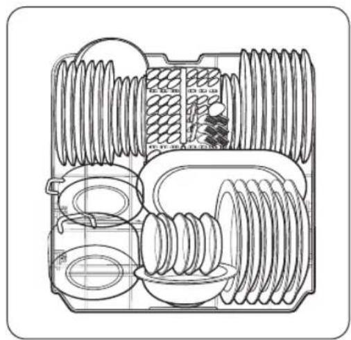
natural_image
Cross-sectional diagram of a mechanical assembly with threaded components and housing (no text or labels)text_image
DW6*R707* DW6*R705* DW6*R707* DW6*R705* DW6*R704*Panier supérieur
natural_image
Technical line drawing of a mechanical component with multiple circular features and grid lines (no text or symbols)
natural_image
Technical line drawing of a mechanical assembly with multiple components and no visible text or symbolsnatural_image
Technical diagram of a heat exchanger or cooling unit with internal flow patterns (no text or labels)natural_image
Technical line drawing of a mechanical assembly with two cylindrical components mounted on a grid base (no text or symbols visible)natural_image
Hand inserting a device into a plastic case with a black arrow indicating the component (no text or symbols present)natural_image
Illustration of a device being inserted into a tray with a lid (no text or symbols)natural_image
Isometric diagram of a device casing with an arrow indicating direction (no text or symbols)natural_image
Illustration of a hand pouring liquid onto a flat surface with a small inset device (no text or symbols)natural_image
Hand inserting a device into a device casing with an arrow indicating rotation (no text or symbols)natural_image
Illustration of a milk bottle pouring liquid into a container on a tiled surface (no text or symbols)natural_image
Diagram of a mechanical device with a black arrow pointing to a component (no text or symbols present)natural_image
Diagram showing a gear mechanism interacting with a device panel (no text or symbols)natural_image
Line drawing of a coffee cup pouring liquid from a container into a tray (no text or symbols)natural_image
Diagram of a mechanical component with a gear and curved arrow indicating rotation (no text or symbols)natural_image
Technical line drawing of a mechanical assembly with an inset circular detail showing a component (no text or symbols)Gicleur inférieur
natural_image
Technical diagram of a mechanical assembly with gears and a lever (no text or symbols)natural_image
Technical diagram of a mechanical component with a central cylindrical housing and surrounding components (no text or symbols)natural_image
Diagram of a mechanical component with a circular housing and directional arrow, no text or symbols present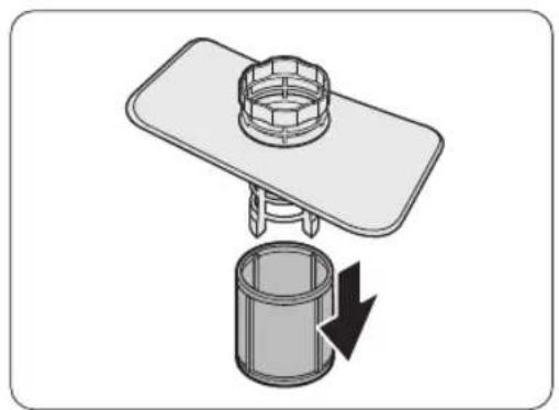
natural_image
Diagram of a mechanical assembly with a cylindrical component and a flat plate, showing a downward rotation arrow (no text or symbols)Entretien
natural_image
Technical line drawing of a mechanical component grid with circular holes and a central oval (no text or symbols)Panier inférieur

natural_image
Technical line drawing of a mechanical assembly with multiple threaded components (no text or symbols)text_image
Technical diagram with numbered components and layered structure, likely representing a mechanical or electrical component layout.
natural_image
Technical line drawing of a mechanical assembly with rollers, gears, and a housing (no text or symbols)Panier inférieur

natural_image
Cross-sectional technical drawing of a mechanical assembly (no visible text or labels)natural_image
Diagram of a grid-like cell or particle array with numbered cells, no text or symbols present
text_image
Diagram showing a grid of oval cells with numbered labels inside, likely representing a cell division or arrangement.
DW6*R707*/DW6*R705*/DW6*R704* Series

text_image
SAMSUNGContents
Safety information 4
What you need to know about safety instructions 4 Important safety symbols 4 Instructions about the WEEE 5 Important safety precautions 6 Instructions when using your dishwasher 8 Instructions for protecting your children 9 Instructions for installing your dishwasher 10
Installation 13
What's included 13 Installation requirements 16 Step-by-step installation 18 Skirting board 35 Kick plate (DW6*R70**U* Series) 37
Before you start 38
Dishwasher at a glance 38
Unsuitable items for the dishwasher 40
Basic use of racks 41
Detergent compartment 45
Rinse aid reservoir 47
Salt storage 48
Touchpad responsiveness 49
Setting mode 50
Operations 52 Control panel 52 Cycle overview 54 Simple steps to start 55 Salt storage 56 Delay Start 58 Control Lock 58
Maintenance 59 Cleaning 59 Long-term care 62
Troubleshooting 63 Checkpoints 63 Information codes 66
English2
Cycle chart 67
Appendix 69
Transportation/relocation 69
Protection against frost 69 Disposing the dishwasher and helping the environment 69 Specifications 70
For standard test 71
English 3
Safety information
Congratulations on your new Samsung dishwasher. This manual contains important information on the installation, use and care of your appliance. Please take time to read this manual to take full advantage of your dishwasher's many benefits and features.
What you need to know about safety instructions
Please read this manual thoroughly to ensure that you know how to safely and efficiently operate the extensive features and functions of your new appliance and retain it at a safe place near the appliance for your future reference. Use this appliance only for its intended purpose as described in this user manual.
Warning and important safety instructions in this manual do not cover all possible conditions and situations that may occur. It is your responsibility to use common sense, caution, and care when installing, maintaining, and operating your dishwasher.
Because the following operating instructions cover various models, the characteristics of your dishwasher may differ slightly from those described in this manual and not all warning signs may be applicable. If you have any questions or concerns, contact your nearest service center or find help and information online at www.samsung.com.
Important safety symbols
What the icons and signs in this user manual mean:
WARNING
Hazards or unsafe practices that may result in severe personal injury, death and/or property damage.
CAUTION
Hazards or unsafe practices that may result in personal injury and/or property damage.
NOTE
Indicates that a risk of personal injury or material damage exists.
These warning symbols are here to prevent injury to you and others. Please follow them explicitly.
Keep these instructions in a safe place and ensure that new users are familiar with the content. Pass them on to any future owner.
English4

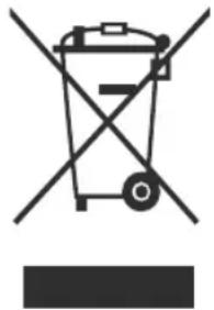
Instructions about the WEEE
natural_image
Symbol of a trash bin with no text or labelsCorrect Disposal of This Product (Waste Electrical & Electronic Equipment)
(Applicable in countries with separate collection systems)
This marking on the product, accessories or literature indicates that the product and its electronic accessories (e.g. charger, headset, USB cable) should not be disposed of with other household waste at the end of their working life. To prevent possible harm to the environment or human health from uncontrolled waste disposal, please separate these items from other types of waste and recycle them responsibly to promote the sustainable reuse of material resources.
Household users should contact either the retailer where they purchased this product, or their local government office, for details of where and how they can take these items for environmentally safe recycling.
Business users should contact their supplier and check the terms and conditions of the purchase contract. This product and its electronic accessories should not be mixed with other commercial wastes for disposal.
For information on Samsung's environmental commitments and product specific regulatory obligations e.g. REACH, WEEE, Batteries, visit our sustainability page available via Samsung.com
English 5
Safety information
Important safety precautions
To reduce the risk of fire, electric shock, or injury to persons when using your appliance, follow basic precautions, including the following:
- This appliance is not to be used by persons (including children) with reduced physical, sensory or mental capabilities, or lack of experience and knowledge, unless they have been given supervision or instruction concerning use of the appliance by a person responsible for their safety.
- For use in Europe: This appliance can be used by children aged from 8 years and above and persons with reduced physical, sensory or mental capabilities or lack of experience and knowledge if they have been given supervision or instruction concerning use of the appliance in a safe way and understand the hazards involved. Children shall not play with the appliance. Cleaning and user maintenance shall not be made by children without supervision.
- Children should be supervised to ensure that they do not play with the appliance.
- If the supply cord is damaged, it must be replaced by the manufacturer, its service agent or similarly qualified persons in order to avoid a hazard.
- The new hose-sets supplied with the appliance are to be used and old hose-sets should not be reused.
English6
- For appliances with ventilation openings in the base, a carpet must not obstruct the openings.
- For use in Europe: Children of less than 3 years should be kept away unless continuously supervised.
- CAUTION: In order to avoid a hazard due to inadvertent resetting of the thermal cut-out, this appliance must not be supplied through an external switching device, such as a timer, or connected to a circuit that is regularly switched on and off by the utility.
- WARNING: Knives and other utensils with sharp points must be loaded in the basket with their points down or placed in a horizontal position.
This appliance is intended to be used in household and similar applications such as:
- staff kitchen areas in shops, offices and other working environments;
- farm houses;
- by clients in hotels, motels and other residential type environments;
• bed and breakfast type environments.
Safety information
Instructions when using your dishwasher
This dishwasher is not designed for commercial use. It is intended for use in domestic households and in similar working and residential environments such as:
- Shops
• Offices and showrooms
and by residents in establishments such as:
• Hostels and guest houses.
It must only be used as a domestic appliance as specified in this user manual, for cleaning domestic crockery and cutlery. Any other usage is not supported by the manufacturer and could be dangerous.
The manufacturer cannot be held liable for damage resulting from incorrect or improper use or operation.
Do not use solvents in the dishwasher. Danger of explosion.
Do not inhale or ingest dishwasher detergent. Dishwasher detergents contain irritant or corrosive ingredients which can cause burning in the nose, mouth and throat if swallowed, or inhibit breathing. Consult a doctor immediately if detergent has been swallowed or inhaled.
Avoid leaving the door open unnecessarily, as you could trip over it.
Do not sit or lean on the opened door. This could cause the dishwasher to tip and be damaged, and you could get injured.
Only use detergent and rinse aid formulated for domestic dishwashers. Do not use washing-up liquid.
Do not use any strong acid cleaning agent.
Do not fill the rinse aid reservoir with powder or liquid detergent. This will cause serious damage to the reservoir.
Inadvertently filling the salt reservoir with powder or liquid dishwasher detergent will damage the water softener. Make sure you have picked up the correct packet of dishwasher salt before filling the salt reservoir.
Please only use special coarse grained dishwasher salt for reactivation, as other salts may contain insoluble additives which can impair the functioning of the softener.
In an appliance with a cutlery basket (depending on model), cutlery is cleaned and dried more if placed in efficiently the basket with the handles downwards. However, to avoid the risk of injury, place knives and forks etc. with the handles upwards.
Plastic items which cannot withstand being washed in hot water, such as disposable plastic containers, or plastic cutlery and crockery should not be cleaned in the dishwasher. The high temperatures in the dishwasher may cause them to melt or lose shape.
On models with Delay Start function, make sure that the dispenser is dry before adding detergent. Wipe dry if necessary. Detergent will clog if poured into a damp dispenser and may not be thoroughly dispersed.
English8
Knives and other utensils with sharp points must be loaded in the basket with their points down or placed in a horizontal position.
Instructions for protecting your children
This appliance is not a toy! To avoid the risk of injury, keep children well away and do not allow them to play in or around the dishwasher or to use the controls. They will not understand the potential dangers posed by it. They should be supervised whenever you are working in the kitchen. There is also a danger that children playing might shut themselves in the dishwasher.
This appliance can be used by children aged from 8 years and above and persons with reduced physical, sensory or mental capabilities or lack of experience and knowledge if they have been given supervision or instruction concerning use of the appliance in a safe way and understand the hazards involved. Children shall not play with the appliance. Cleaning and user maintenance shall not be made by children without supervision.
Older children may only use the dishwasher when its operation has been clearly explained to them and they are able to use it safely, recognising the dangers of misuse.
KEEP CHILDREN AWAY FROM DETERGENTS!
Dishwasher detergents contain irritant and corrosive ingredients which can cause burning in the mouth, nose and throat if swallowed, or inhibit breathing.
Keep children away from the dishwasher when the door is open. There could still be detergent residues in the cabinet.
Consult a doctor immediately if your child has swallowed or inhaled detergent.
English 9
Safety information
Instructions for installing your dishwasher
Before setting up the appliance, check it for any externally visible damage. Under no circumstances should you use a damaged appliance. A damaged appliance could be dangerous.
The dishwasher must only be plugged into the electricity supply via a suitable switched socket. The electrical socket must be easily accessible after the dishwasher is installed so that it can be disconnected from the electricity supply at any time. (Refer to the "Dishwasher at a glance" section on page 38.)
There must be no electrical sockets behind the dishwasher. Danger of overheating and fire risk if the dishwasher were to be pushed up against a plug.
The dishwasher must not be installed under a hob. The high radiant temperatures which are sometimes generated by a hob could damage the dishwasher. For the same reason it should not be installed next to open fires or other appliances which give off heat, such as heaters etc.
Do not connect the dishwasher to the mains supply until it has been fully installed and any adjustment has been made to the door springs.
Before connecting the appliance, check that the connection data on the data plate (voltage and connected load) match the mains electricity supply. If in any doubt, consult a qualified electrician.
The electrical safety of this appliance can only be guaranteed when continuity is complete between it and an effective grounding system. It is most important that this basic safety requirement is present and regularly tested and where there is any doubt the electrical system in the house should be checked by a qualified electrician.
The manufacturer cannot be held liable for the consequences of an inadequate grounding system (e.g. electric shock).
Do not connect the appliance to the mains electricity supply by a multi-socket unit or an extension lead. These do not guarantee the required safety of the appliance (e.g. danger of overheating).
This appliance may only be installed in mobile installations such as ships if a risk assessment of the installation has been carried out by a suitably qualified engineer.
English10
The plastic housing of the water connection contains an electrical component. The housing must not be submerged in water.
There are electrical wires in the hose of Aqua-Stop. Never cut the water inlet hose, even if it is too long.
Installation, maintenance and repairs may only be carried out by a suitably qualified and competent person in strict accordance with current national and local safety regulations. Repairs and other work by unqualified persons can be dangerous. The manufacturer cannot be held liable for unauthorised work.
The integrated waterproof system offers protection from water damage, provided the following conditions are met:
- The dishwasher is correctly installed and plumbed in.
- The dishwasher is properly maintained and parts are replaced where it can be seen that this is necessary.
- The stopcock has been turned off when the appliance is not used for a longer period of time (e.g. during holidays).
- The waterproof system will work even if the appliance is switched off. However, the appliance must remain connected to the electricity supply.
A damaged appliance can be dangerous. If the dishwasher gets damaged, switch it off at the mains and call your dealer or the service department.
Unauthorised repairs could result in unforeseen dangers for the user, for which the manufacturer cannot accept liability. Repairs should only be undertaken by an approved service technician.
Faulty components must only be replaced by original spare parts. Only when these parts are fitted can the safety of the appliance can be guaranteed.
Always disconnect the dishwasher from the electrical supply for maintenance work (switch off at the wall socket and remove the plug).
If the connection cable is damaged it must be replaced with a special cable, available from the manufacturer. For safety reasons, this must only be fitted by the service department or an authorised service technician.
In countries where there are areas which may be subject to infestation by cockroaches or other vermin, pay particular attention to keeping the appliance and its surroundings in a clean condition at all times. Any damage which may be caused by cockroaches or other vermin will not be covered by the guarantee.
Safety information
In the event of a fault or for cleaning purposes, the appliance is only completely isolated from the electricity supply when:
- it is switched off at the wall socket and the plug is withdrawn, or
- it is switched off at the mains, or
• the mains fuse is disconnected, or - the screw-out fuse is removed (in countries where this is applicable).
Do not make any alterations to the appliance, unless authorised to do so by the manufacturer.
Never open the casing/housing of the appliance. Tempering with electrical connections or components and mechanical parts is highly dangerous and can cause operational faults or electric shock.
While the appliance is under guarantee, repairs should only be undertaken by a service technician authorised by the manufacturer. Otherwise the guarantee will be invalidated.
When installing the product, make sure there is space at the top, left, right and back of the product to ensure proper ventilation. If there is insufficient space between the product and the sink, it may damage the sink or allow mold to grow.
Make sure that your dishwasher's hardness level setting is correct as your area. (Refer to the "Salt storage" section on page 48.)
English12-
Installation
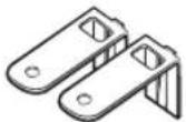
What's included
Make sure all the parts are included in the product package. If you have a question about the dishwasher or the parts, contact a local Samsung customer centre or your retailer. The actual appearance of the dishwasher may differ, depending on your model and country.
CAUTION
After unpacking the dishwasher, keep packaging materials out of children's reach to ensure their safety.
DW6*R707* models only
Upper side trim (1)
FBI (Fully Built-In, DW6*R70**BB) models
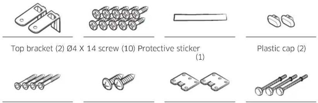
text_image
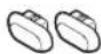
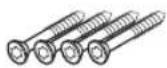
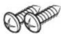
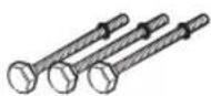
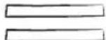
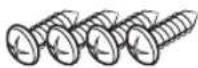
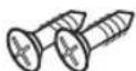
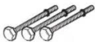
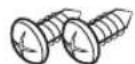
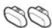
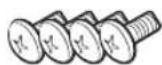
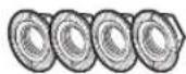
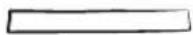
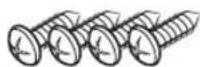
Top bracket (2) Ø4 X 14 screw (10) Protective sticker (1) Plastic cap (2)∅3.5 X 45 screw (4) ∅3.5 X 16 screw (2) Door bracket (2) Sub foot (3)
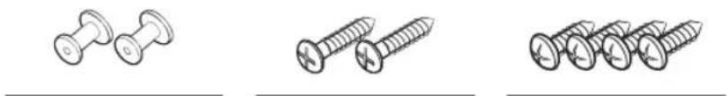
natural_image
Three line drawings of different types of screws, showing different sizes and mounting features (no text or symbols)Custom panel fixer (wood panel holders, 2)
English 13
Installation
SBI (Semi Built-In, DW6\*R70\*\*S\*) models


Top bracket (2) ∅4 X 14 screw (2) Protective sticker
(1)
Plastic cap (2)
∅3.5 X 45 screw (4) ∅3.5 X 16 screw (2) Sub foot (3) Hook-and-loop
fastener (2)
Spacer wood (6) ∅3.9 X 13 screw (4)
BU (Built Under, DW6\*R70\*\*U\*) models
Top brackets (2) ∅4 X 14 screws (2) Sub foot (3) ∅3.5 X 16 screws
(2)
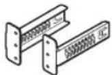
Kick plate brackets (2)
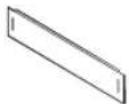
Kick plate Plastic cap (2) Kick plate bolt (4)
Kick plate nut (4) Protective sticker (1)
∅3.9 X 13 screw (4)
English14

Installation kit (not provided)
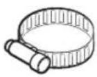
Hose clamp
Tools required (not provided)
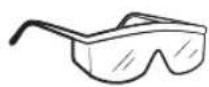
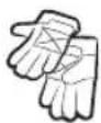
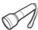
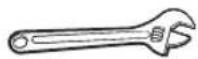
for the front foot
Safety glasses Gloves Flashlight Wrench (22 mm)
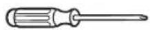
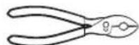
Torx T15 Pliers Nipper Tape measure

screwdriver
Pencil Phillips screwdriver Flat head
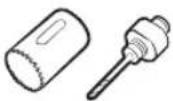
Level Hole saw
(80-100 mm)
Installation
Installation requirements
To prevent a risk of fire, electric shock, or personal injury, all wiring and grounding must be done by a qualified technician.
Power supply
- An individual 220-240 V, 50 Hz branch circuit that is dedicated to the dishwasher.
- Power outlet with a maximum allowable current of 16 A (maximum 11 A for the dishwasher)
WARNING
- Do not use an extension cord.
- Use only the power plug that comes with the dishwasher.
• After installation is complete, make sure the power plug is not bent or damaged.
Grounding
For permanent grounding, the dishwasher must be properly grounded to a grounded metal or permanent wiring system. The grounding conductor must be run with the circuit conductors and then connected to the grounding terminal or lead on the dishwasher.
WARNING
- Do not connect the ground wire to plastic plumbing, gas lines, or hot water pipes. Improperly connected grounding conductors may cause electric shock.
- Do not modify the power plug of the dishwasher. If the power plug does not fit the outlet, have a proper outlet installed by a qualified electrician.
Water supply
- The water supply line must support water pressures between 0.04 and 1 MPa.
• Water temperatures must be lower than 60^ C. - A stopcock with a 3/4" male thread must be installed on the water tap.
To reduce a risk of leaks:
- Make sure water taps are easily accessible.
- Turn the water tap off when the dishwasher is not in use.
- Check for any leaks at the water hose fittings on a regular basis.
- To stop any leak, seal the water line connections and joints using Teflon tape or sealing compound.
Aqua Stop
The Aqua Stop is an electrical component that is designed to prevent water leaks. The Aqua Stop is attached to the water hose and automatically cuts off the water flow in the event of damage to the hose.
CAUTION
- Handle the Aqua Stop with care.
- Do not kink or twist the water hose connected to the Aqua Stop. If the Aqua Stop is damaged, shut off the water taps and unplug the power plug immediately. Then, contact a local Samsung customer centre or a qualified technician.
English16
Drain
If you are using a drain system dedicated to the dishwasher, connect the drain hose to a drain system that is between 30 cm and 70 cm off the ground. Connecting the drain hose to a drain system more than 80 cm off the ground can cause the drained water to flow backward.
Flooring
For safety, the dishwasher must be installed on a solidly constructed floor. Wooden floors may need to be reinforced to minimise vibrations. Avoid installing on carpet or soft tile. Carpeting and soft tile may cause vibrations and may cause your dishwasher to move slightly while operating.

WARNING
Do not install the dishwasher on a poorly supported structure.
Ambient temperature
Do not install the dishwasher in an area exposed to freezing temperatures. The dishwasher always retains some water in the water valve, pump, and hose. If the water freezes in the dishwasher or hoses, it may damage the dishwasher and its components.
Test run
After installing the dishwasher, run the Quick cycle to make sure the dishwasher is installed correctly.
English 17
Installation
Step-by-step installation
The installation procedure may differ depending on the model.
STEP 1 Select a location
natural_image
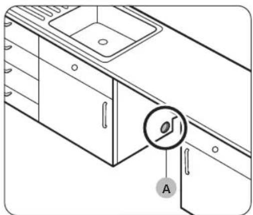
Line drawing of a kitchen sink with a circular component labeled 'A' pointing to the door (no text or symbols beyond label)
natural_image
Technical line drawing of a kitchen sink and cabin with pipes and fixtures (no text or symbols)Select a location that meets the following conditions.
- The location must have a solid floor that can support the weight of the dishwasher.
- The location must be near a sink with easy access to the water supply, drain system, and electrical outlet.
- The location must let you load dishes into the dishwasher easily.
- The location must have sufficient space for the dishwasher door to open easily and provide enough space between the dishwasher and the cabinet sides.
- The rear wall must be free of obstructions.
Installation in a new location
If you install the dishwasher in a new location, follow these instructions before installing the dishwasher.
- Using a hole saw, cut a hole into the side of the cabinet that holds the sink (A).
- If the base inside the sink cabinet is raised above the kitchen floor and is higher than the connections on the dishwasher, make a hole in the base inside the cabinet and in the cabinet side (B).
NOTE
- If you are replacing an old dishwasher, check the existing connections for compatibility with the new dishwasher and replace the connections as needed.
- You may need to cut a hole in the opposite side of the cabinet according to the location of the electrical outlet.
English18-
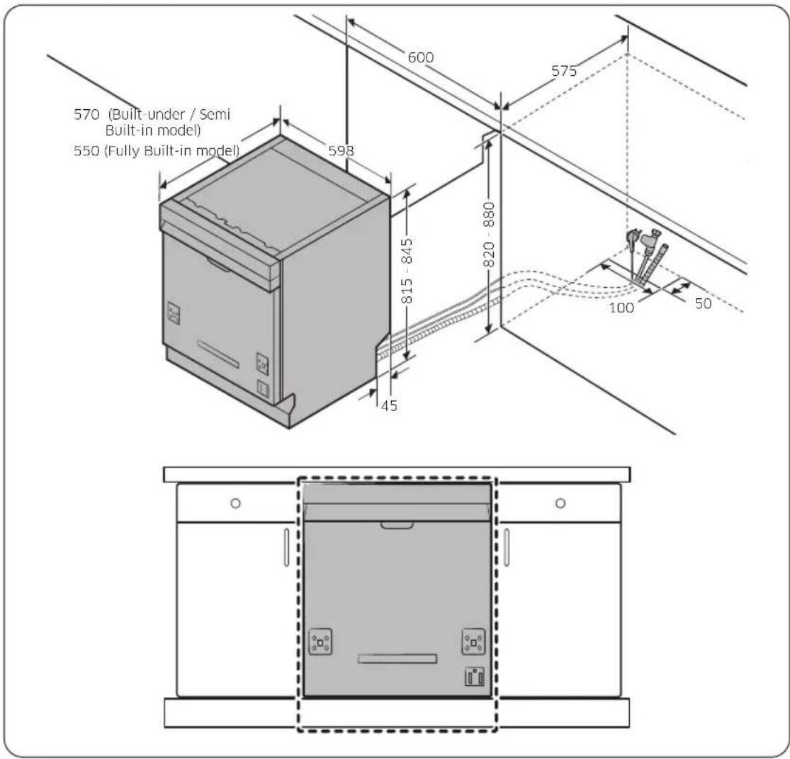
Cabinet dimensions
text_image
570 (Built-under / Semi Built-in model) 550 (Fully Built-in model) 600 575 598 815 - 845 820 - 880 45 100 50Installation
NOTE
Check if the distance between the floor and the bottom of the worktop is more than 850 mm. If so, insert the sub foot included in the installation kit. For details, see the next section. If the distance is less than 850 mm, skip to STEP 3.
English 19

Installation
STEP 2 To insert the sub foot (Except Free Standing model)
If the distance between the floor and the bottom of the worktop is more than 850 mm, insert the sub foot into the hole on the bottom of the dishwasher before you start the installation.
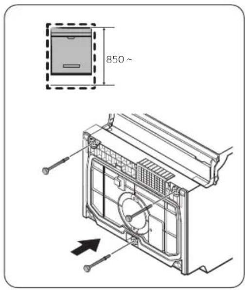
text_image
850~- Lay the dishwasher on its back.
CAUTION
Do not lay down the dishwasher on its side. Water may leak.
- Find the sub foot in the installation kit, and then insert the sub foot into the hole on the bottom of the dishwasher as shown in the figure.
STEP 3 Check the water line
- The water line pressure must be between 0.04 and 1.0 MPa.
- Make sure that the water temperature does not exceed 60 °C. Hot water over 60 °C may cause the dishwasher to malfunction.
- Make sure that the water supply valve is turned off before connecting the water supply line to the dishwasher.
English20
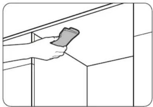
STEP 4 Arrange the hoses
natural_image
Line drawing of a hand holding a smartphone against a wall-mounted shelf (no text or symbols)- Clean the bottom of the countertop.
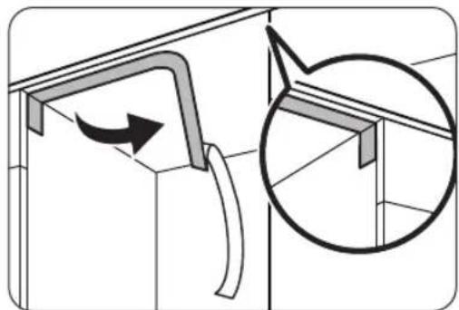
natural_image
Technical diagram showing a structural component with an arrow indicating rotation, and a magnified inset of a bracket detail (no text or symbols)- Attach the protective sticker as shown.
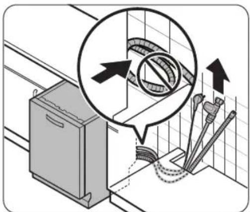
text_image
Diagram illustrating a kitchen appliance inspection with labeled parts and directional arrows indicating inspection zones.- Pull the power plug, the water hose, and the drain hose through the sink hole.
CAUTION
- Use caution not to kink or step on the power plug or the hoses.
- Do not remove the brown paper on the back of the dishwasher. The paper is used to keep the rear side clean against the wall.
English 21
Installation
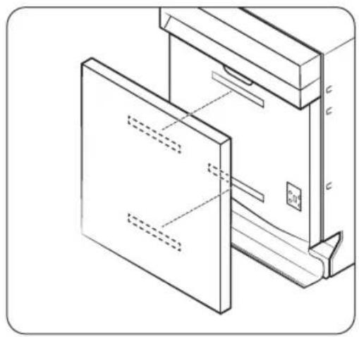
STEP 5 Install the custom panel (For Fully Built-In and Semi Built-In models)
FBI (Fully Built-In, DW6*R70**BB) models

text_image
Technical diagram showing a 3D mechanical assembly with labeled components and a magnified inset of a cylindrical feature.- Put the installation template on the back of the custom panel and fix it temporarily using transparent tape. Note that the rear of the custom panel will be attached to the dishwasher door.
CAUTION
- The top end of the custom panel must be aligned with the top end of the installation template.
- Use a custom panel between 3 kg and 7 kg.
- Mark 14 points guided on the installation template.
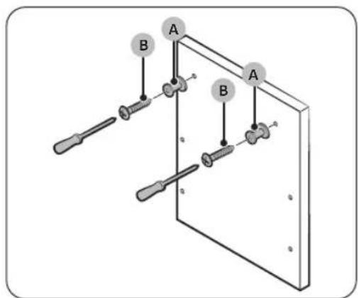
- Remove the installation template, and then tighten the custom panel fixers (A) with 2 screws (B, ∅3.5 X 25) as shown in the figure.
English22-


text_image
Diagram showing a screwdriver inserted into a base plate with labeled components C, D, and others.
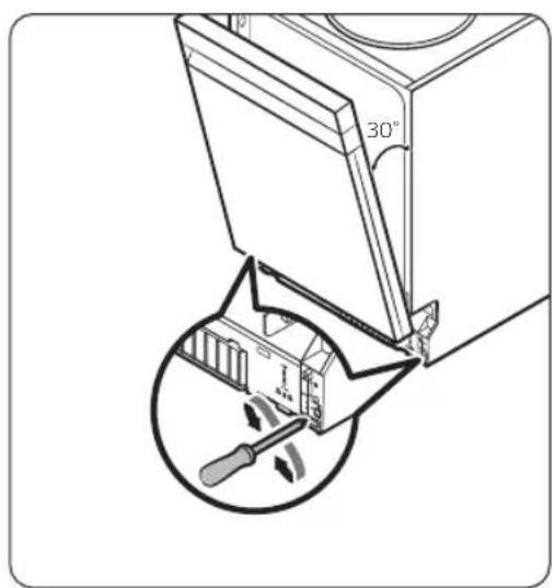
text_image
A F 30 mm C E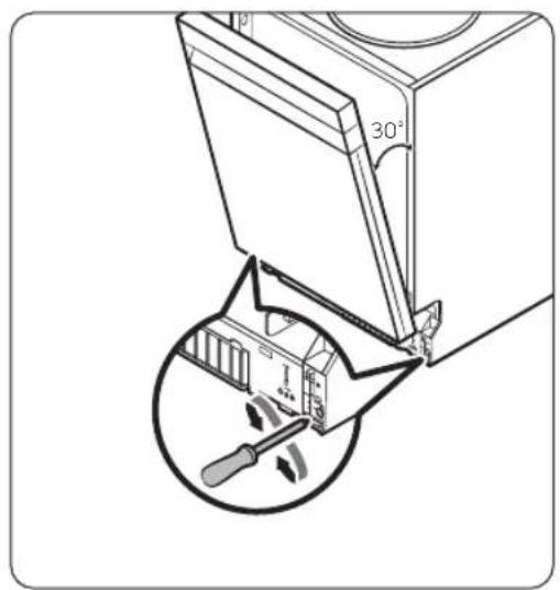
text_image
30°-
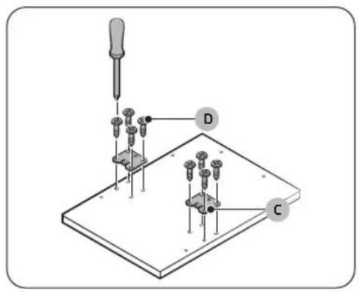
Tighten the door bracket (C) with 8 screws (D, ∅4 X 14) as shown in the figure.
-
Insert the door brackets (C) on the custom panel to the holes (E) on the dishwasher door to fix the custom panel.
- While holding the custom panel, attach it to the door and insert the custom panel fixers (A) into the holes (F) as shown in the figure.
- Push the custom panel downward to fix.
CAUTION
Do not let the custom panel extend more than 30 mm from the top of the dishwasher.
- Adjust the spring level while the door is approximately opened at 30 degrees. The door should hold its position, and should not fall open.
CAUTION
- Do not adjust the spring level while the door is completely opened.
- If the custom panel weighs more than 7 kg, the door may fall open.
- Custom panels weighing more than 7 kg are not recommended.
Installation
installation
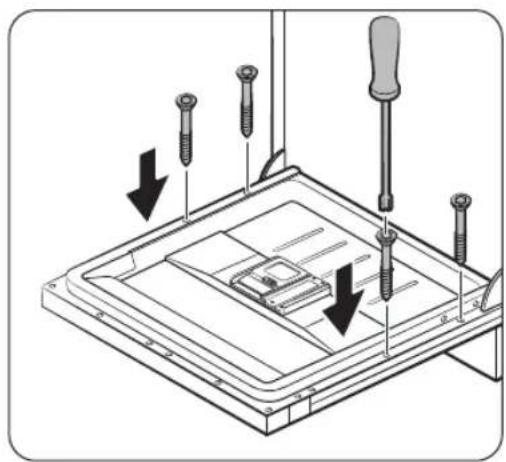
natural_image
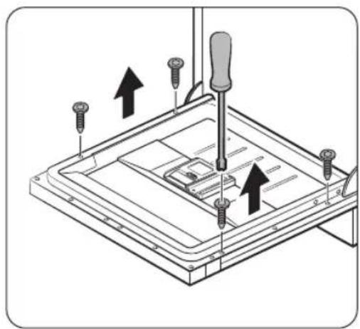
Diagram of a screwdriver installing or adjusting a component on a flat plate (no text or symbols present)- Open the dishwasher door and remove the 4 screws.
CAUTION
Use caution when opening the door. The door might open or close unexpectedly if the spring level is not adjusted appropriately, resulting in physical injury.
natural_image
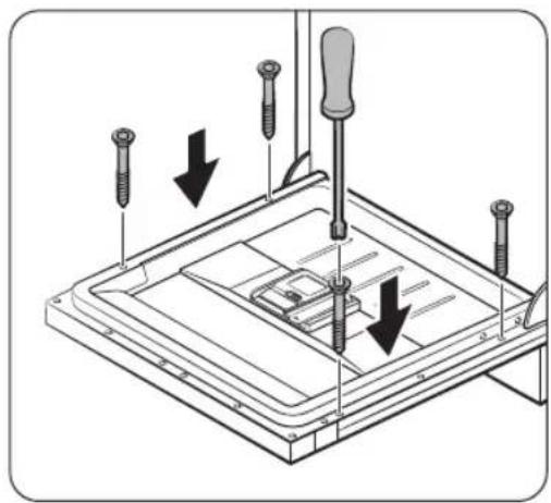
Technical diagram showing screwdriver installation with downward arrows indicating assembly or repair (no text or symbols present)- Secure the custom panel to the door by fastening the 4 screws (3.5 X 45).
English24
SBI (Semi Built-In, DW6\*R70\*\*S\*) models
natural_image
Diagram showing a window or panel installation with a magnified inset highlighting a section detail (no text or symbols present)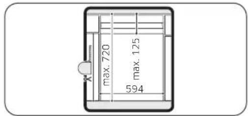
text_image
max. 720 max. 125 594
text_image
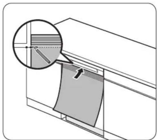
Diagram illustrating a device with labeled components and directional arrows, likely illustrating a process or system setup.- Fully insert the dishwasher under the countertop.
- Align the top of the installation template to the bottom of the dishwasher's door handle.
-
On the top side of the installation template, mark the spot at the top edge of a cabinet.
-
Put the installation template on the back of the custom panel. And align the marks on the installation template to the top edge of the custom panel.
- Use transparent tape to temporarily fix the installation template to the custom panel.
- On the custom panel, mark the location of the 4 screw holes according to the installation template.
- Remove the installation template.
NOTE
The rear of the custom panel will be attached to the dishwasher door.
Please make sure that the height of the custom panel has to be max. 595 mm.
CAUTION
Use a custom panel between 3 kg and 6 kg.
Installation
natural_image
Technical line drawing of a refrigerant oven with a magnified inset showing airflow direction (no text or symbols)
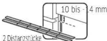
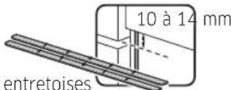
text_image
1 spacer 5-9 mm 10-14 mm 2 spacers 15-19 mm 3 spacers 20-24 mm 4 spacers 25-29 mm 5 spacers 30-34 mm 6 spacers- Pull out the dishwasher halfway from under the countertop.
- Attach single or multiple wood spacers whose overall height fills the gap between the sink cabinet and the control panel.
- The gap here is the same as the measurement in step 5 above.
- For positioning and the number of spacers, see the figures on the left.
CAUTION
Do not let the overall height of the wood spacers exceed the measured height difference. Otherwise, the custom panel may not fit.
English26-
natural_image
Technical line drawing of a door frame assembly with no visible text or symbols
natural_image
Technical diagram of a mechanical assembly with screwdrivers and a base plate (no text or symbols)-
Attach the 2 pcs of hook-and-loop fastener on the door outer and the rear of the custom panel as shown in the figure.
-
Contact the hook-and-loop fasteners to fix the custom panel.
-
Open the dishwasher door and remove the 4 screws.

CAUTION
Use caution when opening the door. The door might open or close unexpectedly if the spring level is not adjusted appropriately, resulting in physical injury.
English 27

Installation
installation
natural_image
Technical diagram showing screwdriver installation on a device with arrows indicating downward motion (no text or symbols present)- Secure the custom panel to the door by fastening the 4 screws (∅4 X 43).
text_image
30°- Adjust the spring level while the door is approximately opened at 30 degrees. The door should hold its position, and should not fall open.
CAUTION
- Do not adjust the spring level while the door is completely opened.
- If the custom panel weighs more than 6 kg, the door may fall open.
- Custom panels weighing more than 6 kg are not recommended.
English28-
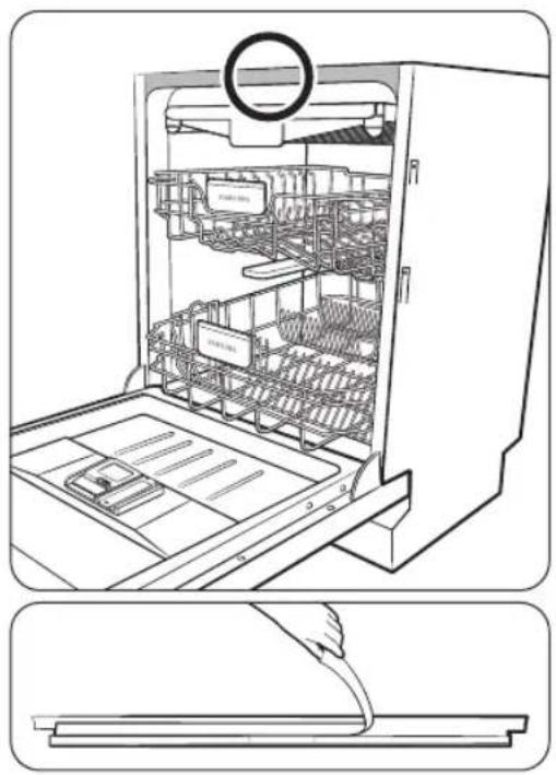
STEP 6 Install the trim (For DW6\*R707\* models)
natural_image
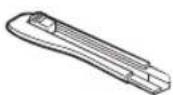
Line drawing of an open refrigerator with internal compartments and a hand inserting a cable (no text or symbols)You can use the trim to reduce the noise level for DW6*R707* models.
- To install the upper side trim, remove the protective vinyl of double-side adhesive tape on the back of the trim.
Installation
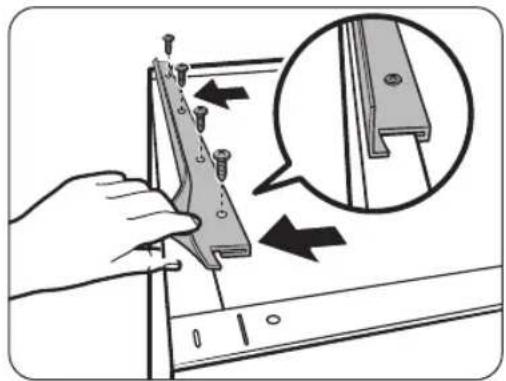
installation
natural_image
Illustration of a hand using a tool to adjust or install a component, with an inset showing the detail of the component (no text or symbols present)-
Insert the Hook shape of the trim to the rear side of tub top bracket.
-
Fasten the provided screws to the four holes.
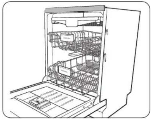
natural_image
Line drawing of an open refrigerator with internal compartments and storage racks (no text or symbols)STEP 7 Level the dishwasher
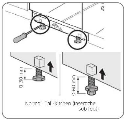
text_image
Normal Tall-kitchen (Insert the sub foot)You can adjust the height of the dishwasher to level it. Note that in these steps, the dishwasher is currently inserted halfway.
- Use the level to check if the dishwasher is level.
- To adjust the front height, use a flat head(-) screwdriver.
• To lower the height, turn the foot counterclockwise.
- To raise the height, turn the foot clockwise.
English30-
text_image
Diagram illustrating a screwdriver tool interacting with a mounted device, with an inset showing a 3D coordinate system.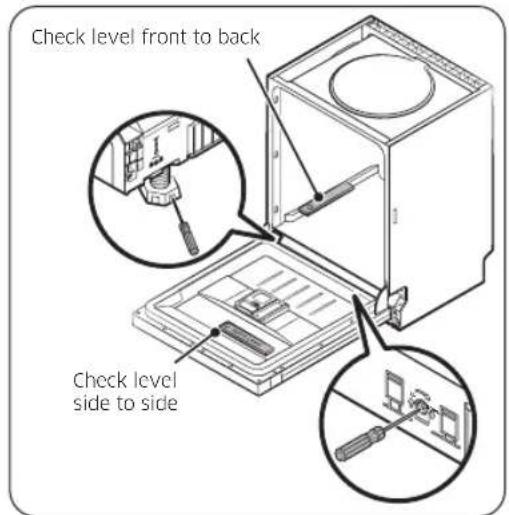
text_image
Check level front to back Check level side to side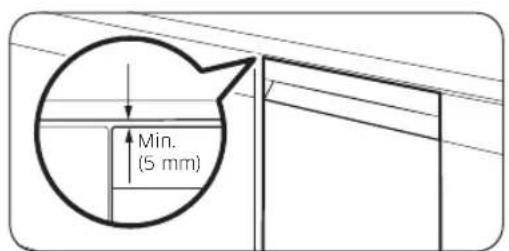
text_image
Min. (5 mm)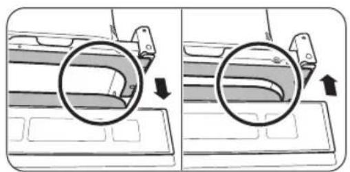
natural_image
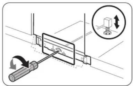
Diagram showing two views of a car interior with a magnified inset highlighting the curved interior (no text or symbols present)- To adjust the rear height, insert a cross head(+) screwdriver in the bottom centre of the dishwasher.
• To lower the height, turn the screwdriver clockwise. - To raise the height, turn the screwdriver counterclockwise.
-
Place a spirit level on door and rack track inside the tub as shown to check that the dishwasher is level.
-
Leave at least a 5 mm space between the top of the dishwasher and the bottom of the countertop.
-
When levelling is complete, check if the door opens and closes properly.
English 31
Installation
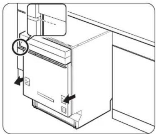
STEP 8 Secure the dishwasher
You can use the brackets to secure the dishwasher to the countertop. Alternatively, you can drill the side holes to secure the dishwasher to the cabinet sides.
To the countertop using the brackets
natural_image
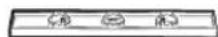
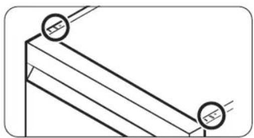
Pure technical line drawing of a structural joint or bracket (no text or symbols)- Insert the provided brackets into the top front holes of the dishwasher as shown.
natural_image
Technical diagram showing a mechanical bracket assembly with an arrow indicating direction (no text or symbols present)- Insert the dishwasher fully into place under the countertop.
text_image
Technical diagram showing a mechanical assembly with labeled components and dimension annotations- Tighten the 2 screws ( 4 × 14 ) to fix the brackets.
NOTE
After fixing the dishwasher to the countertop, some screws remain. You can simply discard these screws, or use them to fix the sides of the dishwasher to the cabinet if you want to.
- Connect the water hose, but do not open the water tap until installation is complete.
English32-
To the sides
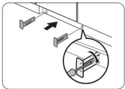
text_image
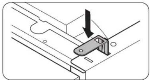
Diagram showing a mechanical or structural component with labeled parts and directional arrows indicating movement or force.
text_image
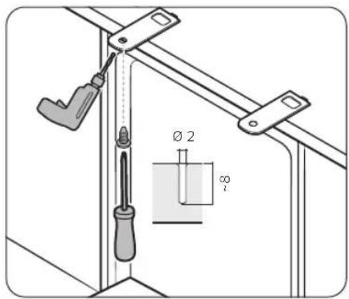
Diagram showing a screwdriver inserted into a corner with a magnified view of the screw, indicating tool application or repair process.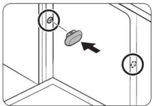
text_image
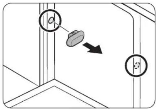
Diagram showing a mechanical or structural component with labeled parts and an arrow indicating direction, possibly illustrating a motion or assembly.
CAUTION
If the plastic caps are not assembled, water may leak and cause a fire or electric shock.
-
Remove the plastic caps.
-
Tighten the 2 screws (∅3.5 X 16) to the 2 places (marked on the illustration).
- Insert the provided plastic caps to the 2 places where screws are fastened.
- Connect the water hose, but do not open the water tap until installation is complete.
Installation
STEP 9 Connect the drain hose
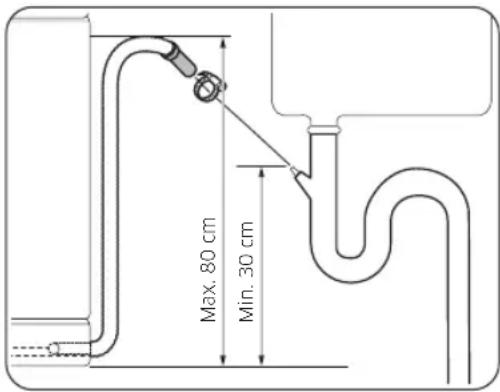
text_image
Max. 80 cm Min. 30 cm- Connect the drain hose to the drain outlet.
CAUTION
• Install the drain system properly so that the drain hose does not come out of the drain outlet in the draining process.
- Make sure that the drain hose, supply hose, and power cord is not kinked or folded.
STEP 10 Final check
- Remove all foam, paper packaging, and unnecessary parts from inside the dishwasher.
- Turn the circuit breaker on.
- Open the water supply valve to supply water to the dishwasher.
- Plug in and turn the dishwasher on. Then, select and run the Quick cycle.
- Check if the dishwasher turns on normally and if there are any water leaks while the dishwasher is operating. Make sure to check for water leaks on both ends of the water line and the drain hose connector.
English34
Skirting board
You can attach the skirting board according to the model or installation conditions.
Skirting board
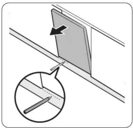
natural_image
Diagram showing a panel being inserted into a metal sheet, with an inset magnified view of the cutting edge detail (no text or symbols present)- Put the skirting board on the bottom of the dishwasher.
-
Open the door of the dishwasher, and draw a baseline on the skirting board where it interferes with the door.
-
Follow the baseline and cut the skirting board using a saw.
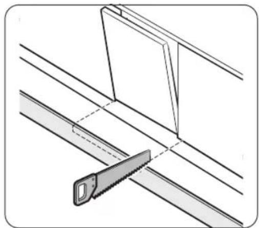
natural_image
Diagram showing a hand using a saw to cut through a metal frame (no text or symbols present)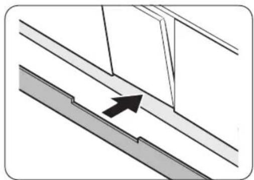
natural_image
Diagram showing a structural joint with an arrow indicating direction (no text or symbols present)- Attach the cut skirting board to the bottom of the dishwasher. Make sure the board does not interfere with the door of the dishwasher.
English 35
Installation
Pre-cut skirting board (DW6\*R70\*\*U\* Series)
text_image
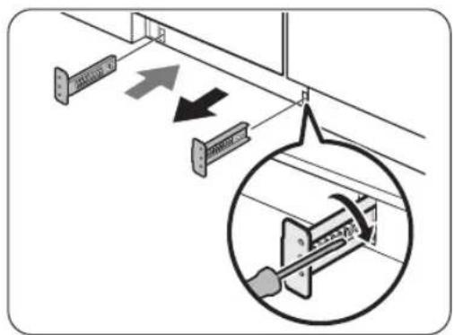
Diagram showing electrical wiring connections with labeled components and directional arrows, including a magnified inset of a mechanical component.- Insert the provided brackets to the bottom of the dishwasher. Turn them into position.
- See the figure on the left for the correct attaching sequence and place of the brackets.
text_image
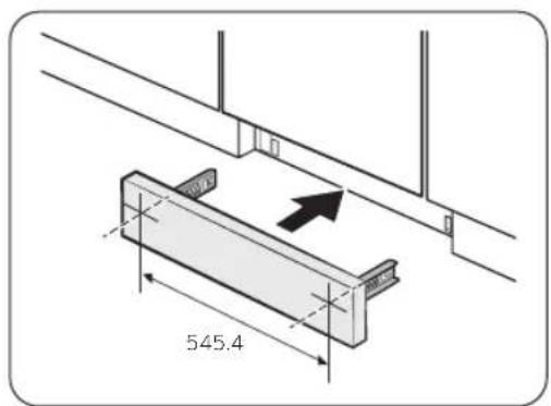
545.4- Insert the pre-cut skirting board into the brackets first, and then tighten the screws to fix the board. See the figure on the left and make sure the brackets are positioned in the correct place.
CAUTION
Make sure the skirting board does not interfere with the dishwasher's door opening and closing.

natural_image
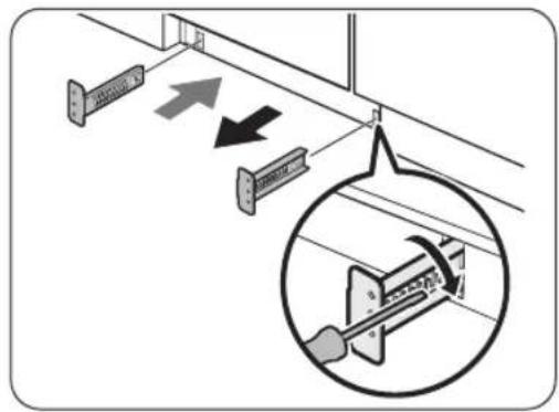
Diagram showing a diagonal line with a shaded rectangular section and an arrow pointing to it (no text or symbols)- Push the skirting board with the brackets into the bottom of the dishwasher as shown.
English36-
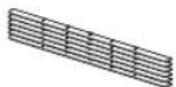
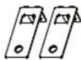
Kick plate (DW6\*R70\*\*U\* Series)
If you want to install the kick plate, follow these steps.
text_image
Diagram showing mechanical assembly with arrows indicating direction and magnified detail view- Insert the provided brackets to the bottom of the dishwasher. Turn them into position.
- See the figure on the left for the correct attaching sequence and place of the brackets.
- Insert the kick plate into the brackets first, and then tighten the 4 kick plate bolts and nuts to fix the kick plate.
NOTE
If the dishwasher is raised by leveling the foot, move kick plate down so that the kick plate fits in bottom.
3. Push the kick plate with the brackets into the bottom of the dishwasher as shown.
CAUTION
Make sure the kick plate does not interfere with the dishwasher's door opening and closing.
text_image
Diagram showing cable installation with labeled components and a magnified inset highlighting a mechanical component.
natural_image
Diagram showing a screwdriver inserted into a mechanical component with an inset close-up of the component (no text or symbols present)English 37
Before you start
Follow these instructions carefully to ensure proper installation of the dishwasher and to prevent accidents when washing dishes.
Dishwasher at a glance
DW6*R707*/DW6*R705* models
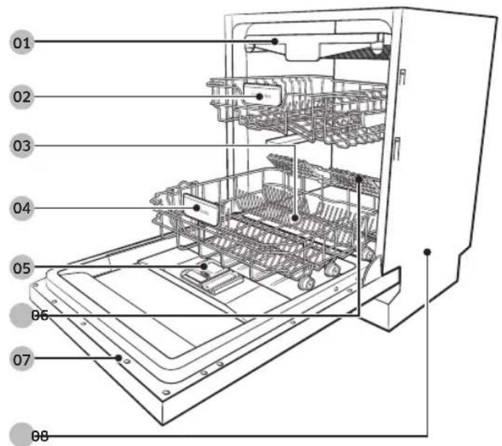
text_image
01 02 03 04 05 06 07 08
text_image
09 1001 Cutlery rack
02 Upper rack
03 Salt storage
04 Lower rack
05 Dispenser
06 Glass support (DW6*R707* model)
07 Door
08 Base
09 Inlet hose
10 Drain hose
English38-
DW6*R704* models
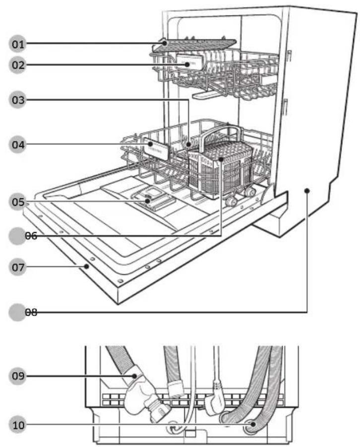
text_image
01 02 03 04 05 06 07 08 09 1001 Knife rack
02 Upper rack
03 Salt storage
04 Lower rack
05 Dispenser
06 Cutlery basket
07 Door
08 Base
09 Inlet hose
10 Drain hose
English 39

Before you start
CAUTION
- Do not wash items that are covered with ash, sand, wax, lubricating grease, or paint. These materials will damage the dishwasher. Ash does not dissolve and will spread inside the dishwasher.
- Remove food remains such as bones, fruit seeds, etc. and waste such as toothpicks, paper napkins, etc. from your dishes. Food remains and waste can make noise, cause the dishwasher to malfunction, and damage your dishes and dishwasher.
Unsuitable items for the dishwasher
WARNING
Wash only items such as glass, porcelain, and cutlery which the manufacturer declares as dishwasher safe. Do not wash aluminium (e.g. grease filters). The dishwasher may damage aluminium, or in extreme cases, cause a severe chemical reaction.
Do not wash the following items in the dishwasher.
• Copper, brass, tin, ivory, and aluminium items or items with adhesive
• Non-heat resistant plastics
- Craft items, antiques, valuable vases, and decorative glassware
• Pottery or glazed-ceramic items
- Wooden cutlery and crockery or items with wooden parts
- Delicate glassware or glassware containing lead crystal. Clouding may occur on the glassware after frequent washing.
NOTE
Silverware that has contacted foods containing sulphur may become discoloured. Food with sulphuric content include egg yolks, onions, mayonnaise, mustard, fish, fish brine, and marinades.
English40
Basic use of racks
Height adjustment
You can adjust the height of the upper rack so that the lower rack can accommodate larger sized dishes. Depending on the height of the upper rack, the lower rack can accommodate plates up to 30 cm in diameter, and the upper rack can accommodate plates up to 18 cm (with Cutlery rack) or 25 cm (without Cutlery rack) in diameter.
CAUTION
- Adjust the height of the upper rack before loading dishes into the rack. Adjusting the rack after loading the dishes may damage the dishes.
- Make sure to hold both handles when adjusting, or the dishwasher door may not close properly.
natural_image
Diagram of a mechanical assembly inside a refrigerator, showing internal components and a magnified view of the device (no text or symbols present)- To raise the upper rack, pull the upper rack upwards. The adjustable handle will latch, and the upper rack will raise.
- To lower the upper rack, hold both the adjustable handles located at the left and right sides of the upper rack, and then evenly press down.
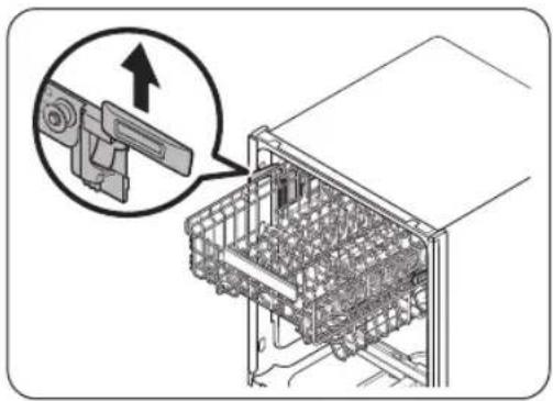
Upper rack removal
CAUTION
- Do not operate the dishwasher without the upper rack. Otherwise, noises occur and the dishwasher does not operate properly.
- Because the upper rack is removable, insert the upper rack properly to ensure the dishwasher operates normally.
Pull the upper rack to the front until it is fully extended, and then lift it slightly to remove. See the following figures.
natural_image
Three-step diagram showing mechanical assembly or assembly process, with no visible text or symbolsEnglish 41
Before you start
Loading dishes
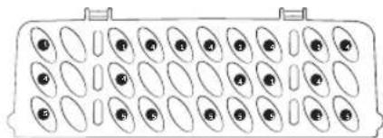
Lower rack
We recommend that you place large items, that are difficult to clean (such as pots, pans, lids, serving dishes and bowls), in to the lower rack.
It is preferable to place serving dishes and lids on the side of the racks in order to avoid blocking the rotation of the upper nozzle. Pots, serving bowls, etc. must always be placed top down.
Deep pots should be slanted to allow water to flow out.
The lower rack features folding tines to easily load more larger pots and pans.

DW6*R707*/DW6*R705* models DW6*R704* models
NOTE
Long items, serving cutlery, salad servers and big knives should be placed on the shelf so that they do not obstruct the rotation of the nozzles.
English42-
Using the folding tines
For better stacking of pots and pans, the tines can be folded down as show in the figure.
text_image
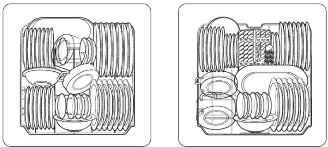
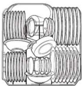
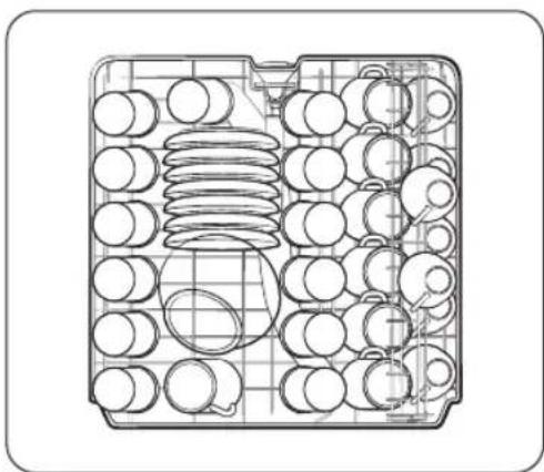
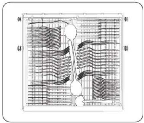
DW6*R707* DW6*R705* DW6*R707* DW6*R705* DW6*R704*Upper rack
The upper rack is designed to hold more delicate and lighter dishware such as glasses, coffee and tea cups and saucers, as well as plates, small bowls and shallow pans (as long as they are not too dirty). Position the dishes and cookware so that they will not get moved by the spray of water. Always place glasses, cups & bowls upside down.
natural_image
Technical line drawing of a mechanical component with multiple circular holes and a central cylindrical feature (no text or symbols)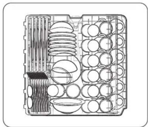
natural_image
Technical line drawing of a multi-compartment storage unit with plates, bowls, and a rack (no text or labels)DW6*R707*/DW6*R705* models DW6*R704* models
English 43

Before you start
Cutlery rack (DW6*R707*/DW6*R705* models)
natural_image
Technical diagram of a heat exchanger or cooling unit with internal flow patterns (no text or labels)The cutlery rack is best for flatware and cooking or serving utensils. Use the cutlery rack to organize flatware or utensils.
NOTE
The cutlery rack can be removed if you need more space on the upper rack to clean larger items.
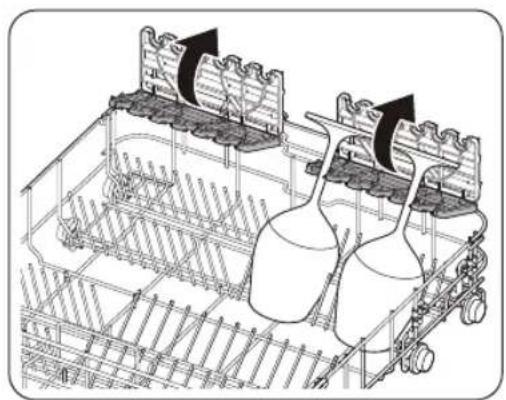
Using the glass support (For DW6*R707* models)
natural_image
Technical line drawing of a mechanical assembly with two cylindrical components and mounting brackets (no text or symbols)The glass support is especially suited for wine glasses. Hang wine glasses onto the pegs of the glass support. Fold the glass support back when it is not being used.
English44
Detergent compartment
All dishwasher cycles require detergent in the detergent compartment. Apply detergent as recommended for the selected cycle to ensure best performance.

WARNING
- Do not place dishwasher detergent in your mouth. Avoid breathing in detergent fumes. Dishwasher detergent contains irritants and caustic chemicals that can induce respiratory conditions. If you have consumed dishwasher detergent or inhaled detergent fumes, seek medical attention immediately.
- Keep dishwasher detergent out of children's reach.

CAUTION
Use dishwasher detergent only. Other types of detergent produce excessive foam, which may decrease the dishwasher's performance or cause it to malfunction.
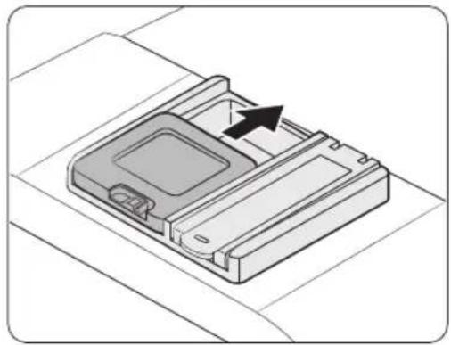
Filling the detergent
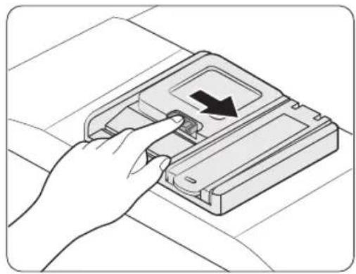
natural_image
Hand inserting a device into a plastic case with a black arrow indicating the component (no text or symbols present)- Open the detergent dispenser cap by pushing the detergent dispenser catch to the right.

NOTE
The cap remains open at the end of a cycle.
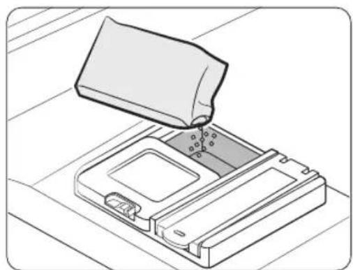
natural_image
Illustration of a device being inserted into a tray with a lid (no text or symbols)- Add the recommended amount of detergent to the main wash detergent compartment.
Before you start
Before you start
natural_image
Isometric diagram of a device casing with an arrow indicating direction (no text or symbols)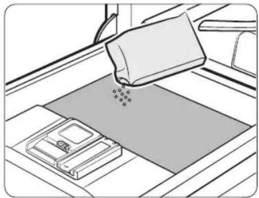
natural_image
Illustration of a hand pouring liquid onto a flat surface with a device on the floor (no text or symbols)-
Close the lid by sliding it up.
-
If the items are heavily soiled, pour a small amount of detergent onto the door for better cleaning results.
NOTE
The additional detergent will activate during the pre-wash process.
The cover opens automatically to dispense the detergent during the wash.
English46-
Rinse aid reservoir
Rinse aid improves the drying performance of the dishwasher. When the Rinse Refill indicator lights up on the control panel, refill with rinse aid. Only use liquid rinse aid. Powdered rinse aid will clog the reservoir opening and cause the dishwasher to malfunction.

CAUTION
- Do not apply any type of detergent to the rinse aid reservoir.
- Do not excessively fill the reservoir. Excessive rinse aid may overflow during a cycle.
Filling the rinse aid
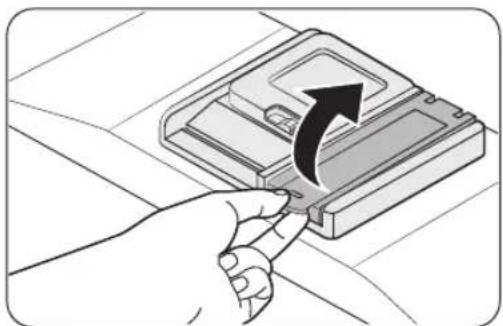
natural_image
Illustration of a hand inserting a USB into a device into a slot, with an arrow indicating the process (no text or symbols present)- Open the rinse aid reservoir cap.
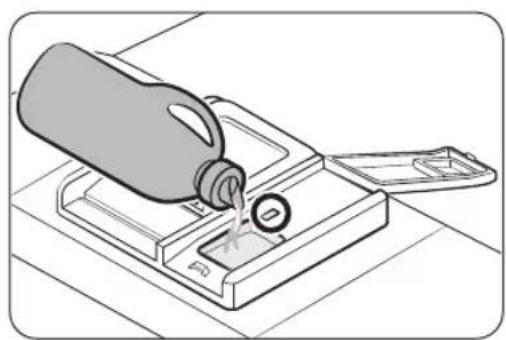
natural_image
Illustration of a bottle pouring liquid into a tray with a lid (no text or symbols)- Fill the rinse aid reservoir with rinse aid.

NOTE
Use the viewing port when filling the rinse aid reservoir.

CAUTION
Do not fill the reservoir above the full level indicator. Excess rinse aid can overflow during the wash cycle.
natural_image
Diagram of a mechanical device with a black arrow indicating a specific component (no text or symbols present)- Close the rinse aid reservoir cap.
Before you start
Salt storage
CAUTION
- Use dishwasher-specific salt only. Do not use any other type of salt or solvent. This may damage the salt storage and the water softening system.
- To prevent corrosion due to an excessive amount of salt or salty water, always fill the salt storage before a washing cycle gets started.
Filling the salt storage
natural_image
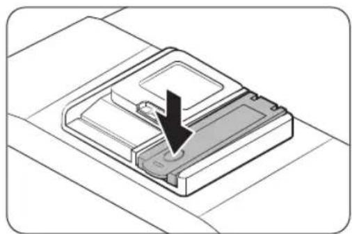
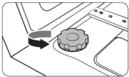
Diagram showing a gear mechanism interacting with a mechanical component (no text or symbols)- Open the door.
- Turn the cap counterclockwise to open.
natural_image
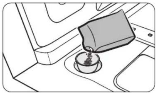
Line drawing of a coffee cup pouring liquid into a container on an airplane (no text or symbols)-
Fill the salt storage with water (only required when using the dishwasher for the first time).
-
Apply dishwasher salt.
natural_image
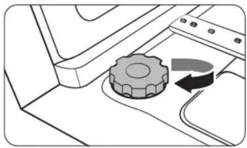
Diagram of a mechanical component with a gear and curved arrow indicating rotation (no text or symbols)CAUTION
- The maximum capacity is about 1 kg. Do not exceed the capacity.
-
Exceeding the capacity may affect the dishwasher performance.
-
Turn the cap clockwise to close.
NOTE
• To clean salt or salt water from dishwasher, run the Quick cycle.
- Depending on the size of the salt grains, it may take a while for the salt to dissolve and the indicator (S) to turn off.
English48-
Salt indicator
The indicator (Turns on if there is not enough salt for the next several cycles.
Touchpad responsiveness
To prevent the touch-enabled controls from losing responsiveness, follow these instructions.
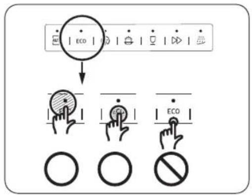
text_image
ECO ECO ECO- Touch the centre of each button with one finger.
- Do not touch more than one button at a time, except as directed.
- Clean the surface of the control panel regularly with a soft, damp cloth.
English 49
Before you start
Setting mode
You can change the sound, auto door open function, rinse aid level, and water hardness settings to your preference.
Entering the Setting mode
- Turn the dishwasher on.
- Press and hold the AUTO cycle button for five seconds within 60 seconds from turning on the dishwasher.
- When you entered the Setting mode, the display will show "0:00".
Sound setting
You can turn the sound on or off.
- Press the Lower rack only button to select the sound setting menu.
-
The display shows the current setting. (Default setting: "U1")
-
Press the AUTO cycle button to change the setting.
- UO: Sound off
- U1: Sound on
- Wait 5 seconds to save the setting.
Auto door open function setting
You can set the dishwasher to automatically open the door after each cycle for better drying results.
- Press the Speed Booster button to select the auto door open function setting menu.
-
The display shows the current setting. (Default setting: "A1")
-
Press the AUTO cycle button to change the setting.
- A0: Function disabled
- A1: Function enabled
- Wait 5 seconds to save the setting.
English50

Rinse aid level setting
You can change the amount of rinse aid applied during a cycle.
- Press the Sanitize button to select the rinse aid level setting menu.
- The display shows the current setting. (Default setting: "d4")
- Press the AUTO cycle button to change the setting.
- You can select from d1 - d5 (minimum - maximum).
- Wait 5 seconds to save the setting.
Water hardness level setting
You can change the water hardness level according to water hardness in your local area. Changing this setting will have effect on the salt consumption in the dishwasher's salt storage.
- Press the Delay Start button to select the water hardness level setting menu.
- The display shows the current setting. (Default setting: "H4")
- Press the AUTO cycle button to change the setting.
- You can select from H1 - H6 (soft - hard).
- Wait 5 seconds to save the setting.
NOTE
- Change the setting according to the table in the "Adjusting salt consumption" section on page 56.
• The manufactory setting: H4 (EN50242) - The dishwasher regenerates the water softener once every 3-4 cycles depending on the setting. However, the dishwasher will regenerate the water softener on the first cycle after you change the setting.
English 51
Operations
Control panel
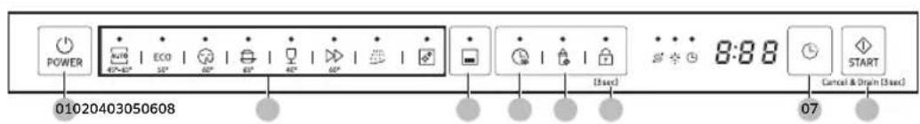
DW6*R707*, DW6*R705* models
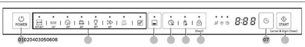
text_image
POWER 01020403050608 ECO 47~49° 50° 50° 49° 49° 50° 50° 50° 50° 50° 50° 50° 50° 50° 50° 50° 50° 50° 50° 50° 50° 50° 50° 50° 50° 50° 50° 50° 50° 50° 5 8:88 START Cancel & Drop in (5 sec) 07DW6*R704* models
text_image
POWER 01020403050608 ECO (See) 8:88 START 07 Cancel & Drain (See)| 01 POWER Press to turn the dishwasher on or off. | |
| 02 Cycle | Press to select a desired wash cycle. For more information, see the “Cycle overview” section on page 54. |
| 03 Lower rack only | Press to wash items using only the lower rack to save energy. |
| 04 Speed Booster | Select this option to reduce the cycle time. This is available only with the AUTO, ECO, Intensive, and Delicate cycles. |
| 05 Sanitize | Press to increase the water temperature up to 69 °C in the final rinse process for high temperature sanitization.This option is not available with Delicate and Pre Wash. |
| 06 Control Lock | Control lock allows you to lock the buttons on the control panel except for the POWER button. For more information, see the “Control Lock” section on page 58. |
| 07 Delay Start | You can delay the cycle starting time up to 24 hours. For more information, see the “Delay Start” section on page 58. |
| 08 START(Cancel & Drain) | Press START to start operation. Make sure the door is closed.Cancel & Drain: To cancel the current cycle and drain the dishwasher, press and hold START for 3 seconds. |
English52-
Indicators
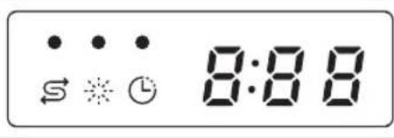
text_image
S ⚠️ ⚠️ S ⚠️ ⏱ 8:88| No Salt indicator Lights up | when the salt storage runs out of salt. | |
| Rinse Refill indicator | Lights up if the dishwasher runs out of rinse aid. | |
| Delay Start indicator | Lights up if Delay Start is activated. | |
English 53

Operations
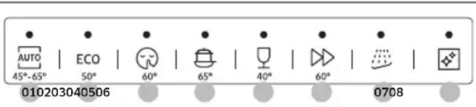
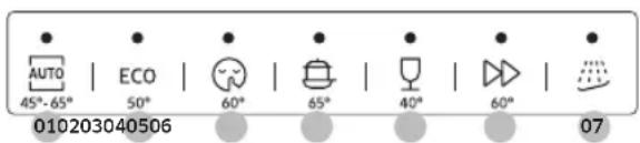
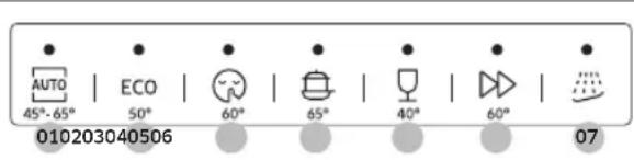
Cycle overview
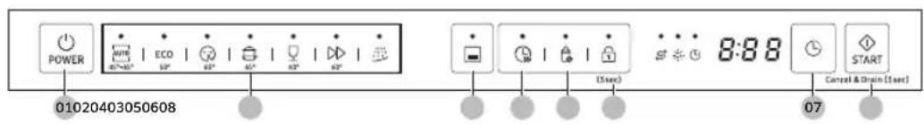
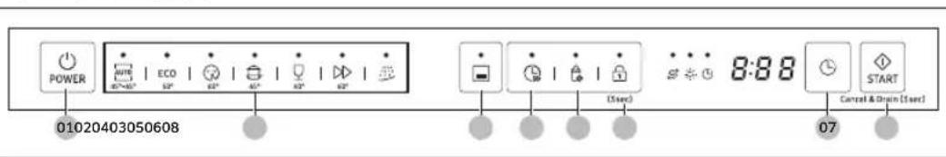
DW6*R707*, DW6*R705* models

text_image
AUTO 45°-65° | ECO | 60° | 65° | 40° | 60° | 0708 010203040506DW6*R704* models
text_image
AUTO 45°-65° | ECO | 60° | 65° | 40° | 60° | 07 010203040506| 01 AUTO | This cycle detects the level of soil and automatically initiates the optimal cycle, which is appropriate for all levels of soiled items. |
| 02 ECO | This cycle reduces power and water consumption, which is appropriate for normally soiled items. |
| 03 Extra Silence | Select this cycle for more smooth and quiet washing. This cycle washes a little bit slower, but creates 2 decibels less noise than the ECO program. |
| 04 Intensive Select this cycle for heavily soiled items. | |
| 05 Delicate | Select this cycle for lightly soiled, fragile items such as glasses. Sanitize option is not available in this cycle. |
| 06 Express | Normally soiled daily using items, with short cycle time. |
| 07 Pre Wash | Cold water rinse for removing dirt before running another program. |
| 08 Self Clean (DW6*R707*/ DW6*R705* models) | Select this cycle to clean the inside of the dishwasher. Make sure the dishwasher is empty. |
English54

Simple steps to start
- Open the door, and then load the dishwasher. Make sure to remove food remains and waste on the dishes.
- Apply detergent to the detergent dispenser. For better results, add rinse aids.
- Press POWER, and then select a cycle with necessary options (Lower rack only, Speed Booster, Sanitize, and Delay Start). Some options may not be available depends on the cycle.
NOTE
If you select Lower rack only, make sure the dishes are loaded in the lower rack.
- Press START, and then close the door. The dishwasher starts the cycle after draining for a few seconds.
NOTE
- To change the cycle after it has started, press and hold START for 3 seconds to cancel the cycle. Then, select a new cycle.
• The default cycle is ECO. - To resume after you have opened the door to stop the dishwasher while operating, simply close the door.
Operations
Salt storage
The water softener is designed to remove minerals and salts from the water, which would have a detrimental or adverse effect on the operation of the appliance. The higher the content of these minerals and salts, the harder your water is. The softener should be adjusted according to the hardness of the water in your area.
Your local Water Authority can advise you on the hardness of the water in your area.
Adjusting salt consumption
The dishwasher is designed to allow for adjusting the amount of salt consumed based on the hardness of the water used. This is intended to optimise and customise the level of salt consumption so that the salt consumption could be set proceed as follows:
- Turn the dishwasher on.
- Press and hold the AUTO cycle button for five seconds within 60 seconds from turning on the dishwasher.
- When you entered the Setting mode, the display will show "0:00".
- Press the Delay Start button to select the water hardness level setting menu.
- The display shows the current setting. (Default setting: "H4")
- Press the AUTO cycle button to change the setting.
- You can select from H1 - H6 (soft - hard).
- Wait 5 seconds to save the setting.
NOTE
- It is recommended that adjustments should be made in accordance with the following (or Manual) table.
• The manufactory setting: H4 (EN50242)
English56
| Water hardness | Water hardness setting | Salt consumption (gram/cycle) | Autonomy (cycles/1 kgs) | |||
| °dH °fH | °Clark m | mol/l | ||||
| 0-5 0-9 | 0-6 0-0 | .94 H1 0 | / | |||
| 6-11 10 | 20 7-14 | 1.0-2.0 | H2 20 60 | |||
| 12-17 21 | 30 15- | 21 2.1-3.0 | H3 30 50 | |||
| 18-22 31 | 40 22- | 28 3.1-4.0 | H4 40 40 | |||
| 23-34 41 | 60 29- | 42 4.1-6.0 | H5 50 30 | |||
| 35-55 61 | 98 43- | 69 6.1-9.8 | H6 60 20 | |||
NOTE
• 1 dH (German degree) = 0.178 mmol/l
• 1 Clark (British degree) = 0.143 mmol/l
• 1 fH (French degree) = 0.1 mmol/l
- Contact your local water board for information on the hardness of your water supply.
- WATER SOFTENER
The hardness of the water varies from place to place. If hard water is used in the dishwasher, deposits may form on dishes and utensils. The appliance is equipped with a special softener that uses a salt specifically designed to eliminate lime and minerals from the water.
English 57
Operations
Delay Start
You can delay the cycle starting time up to 24 hours in 1-hour increments. To increase the delay time, press Delay Start. The hour displayed indicates the time at which the cycle will start.
- Open the door, and then load the dishwasher.
- Press Delay Start to change the time in 1-hour increments.
- If you press and hold the button, the time will increase until you release the button.
- Press START, and then close the door.
NOTE
To change the delay time once the dishwasher has started, press POWER and restart the dishwasher.
Control Lock
To prevent children from playing with the dishwasher, Control Lock locks all button controls except for POWER.
- To activate Control Lock, press and hold Control Lock for 3 seconds. With Control Lock activated, you cannot select a cycle or option, or start an operation.
• To deactivate Control Lock, press and hold Control Lock again for 3 seconds. - Control Lock remains active after the dishwasher restarts. To cancel Control Lock, you must deactivate it first.
English58
Maintenance
Cleaning
Keep the dishwasher clean to improve performance, reduce unnecessary repairs, and lengthen the lifecycle.
Exterior
Clean spills on the surface of the dishwasher immediately. Use a soft, damp cloth on the control panel to gently wipe away spills and dust.

CAUTION
- Do not use benzene, wax, thinner, chlorine bleach, alcohol, or other chemical substances. These materials may discolour the surface of the dishwasher and cause stains.
- The dishwasher has electric parts inside. Do not spray water directly onto the dishwasher. Protect electrical components from water.
- For a stainless-steel door panel, use a stainless steel cleaner for home appliances and a clean, soft cloth.
Interior
Clean the interior of the dishwasher on a regular basis to remove any dirt or food particles. Wipe inside the dishwasher and inside the door with a wet dishcloth.

CAUTION
- Do not remove the front seal (the long rubber seal enclosing the opening of the dishwasher). The seal keeps the inner side of the dishwasher sealed.
- Use a damp cloth to remove lime scale or grease deposits inside the dishwasher. Alternatively, apply some detergent, and then run an empty cycle using the highest rinse temperature.

Maintenance
Nozzles
To prevent the nozzles from being clogged or if the nozzles are clogged, remove and clean each nozzle. Use caution when removing the nozzles as they may break.
Upper nozzle
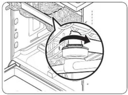
natural_image
Technical line drawing of a mechanical assembly with an inset circular detail showing a component (no text or symbols)Lower nozzle
- Open the door, and then pull out the upper rack to reveal the upper nozzle.
- Loosen and remove the nut, and then remove the nozzle.
- Unclog and clean the nozzle.
- Reinsert the nozzle, and then tighten the nut by hand.
- Rotate the nozzle by hand to make sure the nozzle is engaged correctly.

natural_image
Mechanical assembly diagram showing a rotating shaft and gear mechanism (no text or symbols)-
Open the door, and then pull out the lower rack. The lower nozzle is visible on the bottom.
-
Unclog and clean the nozzle.
-
Reinsert the nozzle.
-
Rotate the nozzle by hand to make sure the nozzle is engaged correctly.
English60
Filter
We recommend cleaning the filter every month.
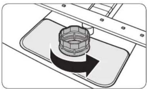
natural_image
Technical illustration of a mechanical component with a central hub and surrounding parts (no text or symbols)- Open the door, and then remove the lower rack first.
- Turn the filter handle counterclockwise to unlock the Coarse filter.
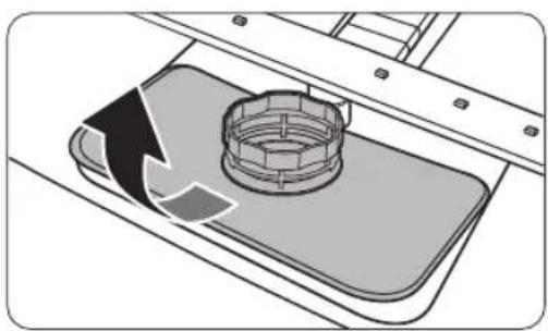
natural_image
Diagram of a mechanical component with a circular housing and directional arrow, no text or symbols present- Remove the Coarse filter, and then the cylindrical micro filter underneath.
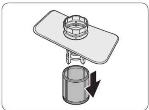
natural_image
Diagram of a mechanical assembly with a cylindrical component and a top plate, showing a downward arrow indicating rotation (no text or symbols present)Maintenance
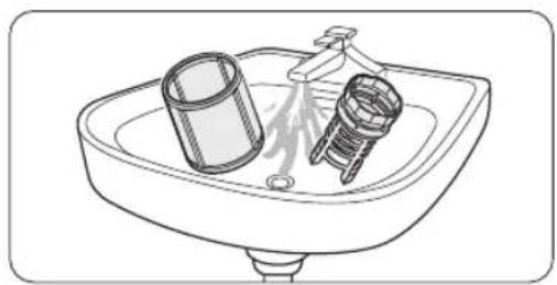
natural_image
Line drawing of a sink with two fixtures, one cylindrical and one threaded, no text or symbols present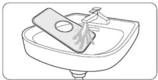
natural_image
Line drawing of a sink with a hand mixer and a plate, no text or symbols present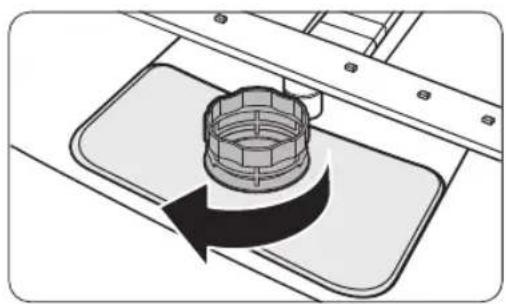
natural_image
Diagram of a mechanical component with a rotating arrow indicating rotation (no text or symbols)- Remove any dirt and impurities from the micro filter and the Coarse filter.
-
Rinse them with running water, and then dry well.
-
Reinsert the filter, and then the Coarse filter.
-
Turn the filter handle clockwise to lock.
CAUTION
Make sure the Coarse filter is closed properly. A loose cover can reduce the filtering performance.
Long-term care
If you will not use the dishwasher for an extended period of time, first drain the unit completely, and then disconnect the water hose. Shut off the water supply valve and the circuit breaker. Water remaining in the hoses or the internal components can damage the dishwasher.
English62-
Troubleshooting
Checkpoints
If you encounter an issue with the dishwasher, first check the table below and try the suggestions.
| Symptom Possible cause Action | ||
| The dishwasher does not start. | The door is not completely closed. | Make sure the door is latched and completely closed.Make sure the upper rack is properly joined with the nozzle.Make sure the upper rack is properly assembled. |
| The power cord is not connected. | Connect the power cord. | |
| Water is not being supplied. | Make sure the water supply valve is open. | |
| The control panel is locked. • Deactivate the Control Lock. | ||
| The dishwasher has bad odours. | Water remains from the previous cycle. | With the dishwasher empty, add detergent, and then run the Quick cycle. This is available only on applicable models. |
| Water remains in the dishwasher after a cycle has finished. | The drain hose is folded or clogged. | Straighten and unclog the hose. |
English 63
Troubleshooting
| Symptom Possible cause Action | ||
| Food remains on dishes. | An incorrect cycle was selected. | Select a cycle according to the soil level of the dishes as instructed in this manual. |
| The filters are clogged or not correctly fastened. | Clean the filters.Make sure the filters are correctly fastened. | |
| An insufficient amount of detergent was used. | Use the correct amount of detergent for each load. | |
| The water pressure is low. | Make sure the pressure is between 0.04-1.0 Mpa. | |
| The nozzles are clogged. | Clean and unclog the nozzles. | |
| Dishes improperly loaded or overloaded. | Arrange the dishes so they do not interfere with the nozzles and/or the detergent dispenser. | |
| The water is too hard. | Check the salt refill indicator, and refill with dishwasher salt. | |
| Dishes are not dried well. | There is no rinse aid in the dispenser, or not enough rinse aid was used. | Add rinse aid.Check the rinse aid settings. |
| Too many dishes are loaded. | Overloading may reduce the drying performance.Load your dishes as recommended. | |
| Glasses and cups spilled water onto other dishes while being unloaded. | Empty the lower rack first, and then the upper rack. This will avoid water dripping from the upper rack onto the dishes in the lower rack. | |
| Multiple detergent tablets were used without selecting the Sanitize option. | Select the Sanitize option or use rinse aid. | |
English64
| Symptom Possible cause Action | ||
| The dishwasher is too noisy. | The dishwasher makes a sound when the dispenser cover is open and the drain pump is operating. | ·This is normal. |
| The dishwasher is not level. | ·Make sure the dishwasher is level. | |
| The nozzle bumps against the dishes, creating a chopping sound. | ·Rearrange the dishes. | |
| Yellow or brown film remains on dishes. | Coffee and tea soils. | ·Use a cycle with a higher temperature. |
| Indicators do not light up. | The power cord is not connected. | ·Connect the power cord. |
| The nozzles do not rotate smoothly. | The nozzles are clogged with food particles. | ·Clean the nozzles. |
| A white coating remains on dishes. | The water is too hard. | ·Make sure the salt fill indicator and softener settings are correct according to the water hardness of your area.·Make sure the salt storage cap is correctly fastened. |
| Air bubbles and scratch marks are on the control panel. | Air gets into the protective film, causing EPS marks to remain. | ·Remove the protective film from the control panel. |
Troubleshooting
Information codes
If the dishwasher fails to operate, you may see an information code on the display. Check the table below and try the suggestions.
| Code Action | |
| LC | Leakage checkClose the water supply valve. Go to your home's circuit breaker panel, and set the dishwasher's circuit breaker switch to off. Then, contact the installer to repair. If the issue continues, contact a local Samsung service centre. |
| 4C | Water supply checkCheck if the water supply valve is closed, if the water supply is suspended, or if the water inlet valve or line is frozen or clogged by foreign particles. If the issue continues, contact a local Samsung service centre. |
| AC | PCB communication checkAbnormal communication between the main PCB and the sub PCB.If the problem continues, contact an authorised Samsung service center. |
| HC | High temperature heating checkFunctional check. With the dishwasher empty, add detergent, and then run a cycle. If the issue continues, go to your home's circuit breaker panel, and set the dishwasher's circuit breaker switch to off. Then, contact a Samsung service centre. |
| tC | Thermistor checkTemperature sensor is broken (short or open circuit). If the problem continues, contact an authorised Samsung service center. |
| EC | Washing pump checkAbnormal working with washing pump. If the issue continues, contact a local Samsung service center. |
| PC | Distribution motor checkAbnormal working with distribution motor assembly, or main PCB. If the issue continues, contact a local Samsung service center. |
If any information code keeps appearing on the screen, contact a local Samsung service centre.
English66
Cycle chart
| Cycle AUTO ECO Intensive | |||
| Amount of food remains | Normal Norma | Heavy | |
| Cycle sequence | Pre wash (45 °C) ▶Main wash (55 °C-65 °C) ▶ Rinse ▶Hot rinse (50 °C - 70 °C) ▶ Dry ▶ End | Pre wash ▶Main wash (50 °C) ▶Rinse ▶Hot rinse (48 °C) ▶Dry ▶ End | Pre wash (50 °C) ▶Main wash (65 °C) ▶ Rinse ▶Hot rinse (58 °C) ▶Dry ▶ End |
| Water consumption (L) | 8.5-18 9.9 16.5 | ||
| Energy consumption (kWh) | 0.85-1.55 | 0.848(DW6*R707***/DW6*R705***)0.836(DW6*R704***) | 1.5 |
| Cycle time (min.) 15 | 0 210 205 | ||
| Cycle Delicate | Express * Pre Wash | ||
| Amount of food remains | Light Normal | Light | |
| Cycle sequence | Pre wash (40 °C) ▶Main wash (50 °C) ▶Rinse ▶Hot rinse (50 °C) ▶Dry ▶ End | Main wash (60 °C) ▶Rinse ▶Hot rinse (55 °C) ▶Dry ▶ End | Pre wash ▶ End |
| Water consumption (L) | 13.5 | 15 | 4.1 |
| Energy consumption (kWh) | 0.95 | 0.95 | 0.02 |
| Cycle time (min.) 120 | 60 | 15 | |
English 67
Cycle chart
| Cycle Extra Silence ** Self Clean | ||
| Amount of food remains | Normal - | |
| Cycle sequence | Pre wash (35 °C) ▶Main wash (60 °C) ▶Rinse ▶Hot rinse (55 °C) ▶Dry ▶ End | Pre wash ▶Main wash (70 °C) ▶Rinse ▶Hot rinse (70 °C) ▶Dry ▶ End |
| Water consumption (L) | 13 15 | |
| Energy consumption (kWh) | 1.5 1.25 | |
| Cycle time (min.) 27 | 0 145 | |
* Pre Wash: This cycle does not activate the Auto Door function nor the drying process. Continuous use of the Pre Wash cycle for an extended time is not recommended. This may reduce the performance of the water softener.
** Self Clean: Only for DW6*R707*/DW6*R705* models
NOTE
- The cycle time depends on the options you have added, and the pressure and temperature of the supplied water.
- The dishwasher drains the remaining water inside automatically if it has not been used for the last 5 days.
- The power consumption depends on the water temperature and/or load. When the rinse aid reservoir is empty, time and temperature can increase a little.
- If no rinse aid is used, the cycle time and temperature may increase slightly.
English68-
Appendix
Transportation/relocation
Make sure the dishwasher is empty with no loose parts. First, drain the dishwasher as follows.
- Open the door, and then turn the dishwasher on.
- Select and run the ECO cycle.
- Press START, and then close the door.
- When the cycle is finished, open the door after 5 seconds.
- Press and hold START for 3 seconds to drain water.
- Close the door.
- When the draining process is complete, open the door.
- Turn the dishwasher off, and then shut the water valve off.
- Disconnect the both the water hose and the drain hose.
CAUTION
Do not shake or sway the dishwasher while moving it. Residual water may drip from the dishwasher.
Protection against frost
If you leave the dishwasher in a place with a risk of frost for an extended time, make sure to empty the dishwasher. For details, see the "Transportation/relocation" section.
Disposing the dishwasher and helping the environment
Your dishwasher is manufactured from recyclable materials. If you decide to dispose of it, please observe your local waste disposal regulations. Cut off the power cord so that the appliance cannot be connected to a power source.
Remove the door so that animals and children cannot get trapped inside the appliance.
English 69
Appendix
Specifications
| MODEL | DW6*R707*F* DW6*R705*F* DW6*R704*F* | DW6*R707*U* DW6*R705*U* DW6*R704*U* | DW6*R707*S* DW6*R705*S* DW6*R704*S* | DW6*R707*BB DW6*R705*BB DW6*R704*BB | |
| Type Free Standing Built Under Semi Built-in Fully Built-in | |||||
| Power 220-240 V | ~, 50 Hz | ||||
| Water pressure 0.04-1.0 MPa | |||||
| Wash capacity | DW6*R707* 14 Place settings | ||||
| DW6*R705* 14 Place settings | |||||
| DW6*R704* 13 Place settings | |||||
| Rated power 1760-2100 W | |||||
| Dimension (Width x Depth x Height) | 598 x 600 x 845 mm 5 | 98 x 570 x 815 mm 598 x 550 x 815 mm | |||
| Weight (Unpacked) | 52.5 kg (707* models) 51 kg (705*/704* models) | 44.5 kg (707* models) 43 kg (705*/704* models) | 44.5 kg (707* models) 43 kg (705*/704* models) | 43 kg (707* models) 42 kg (705*/704* models) | |
English70
For standard test

NOTE
The information for comparability test as follows.
DW6\*R707\*/DW6\*R705\* models
- Washing capacity: 14 place settings
• Test standard: EN 60436 - Position of upper rack: lower position
- Wash cycle: ECO
• Additional options: None - Rinse aid level setting: 5
• Water hardness level setting: H3
• Dosage of the standard detergent: main-wash 22 g - For the arrangement of the items, refer to the below figures
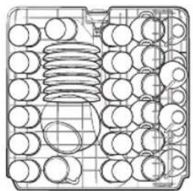
natural_image
Technical line drawing of a mechanical component grid with circular holes and a central oval (no text or symbols)Lower rack
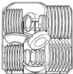
natural_image
Technical line drawing of a mechanical assembly with multiple threaded components (no text or symbols)Cutlery rackUpper rack
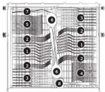
text_image
Technical diagram of a layered structure with numbered components and directional arrows indicating flow or movement.
- Soup spoons 2. Forks
- Knives 4. Teaspoons


- Dessert spoons 6. Serving spoons
7. Serving forks 8. Gravy ladles
English 71
For standard test
DW6\*R704\* models
- Washing capacity: 13 place settings
• Test standard: EN 60436 - Position of upper rack: lower position
- Wash cycle: ECO
• Additional options: None - Rinse aid level setting: 5
• Water hardness level setting: H3
• Dosage of the standard detergent: main-wash 21 g - For the arrangement of the items, refer below figures

natural_image
Technical line drawing of a mechanical assembly with rollers, gears, and a housing (no text or symbols)Lower rack
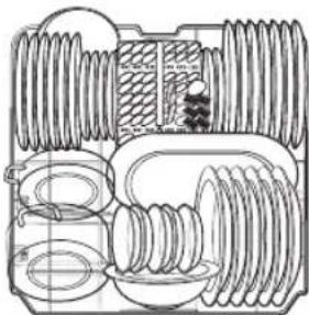
natural_image
Cross-sectional technical drawing of a mechanical assembly (no text or labels)Cutlery rackUpper rack

natural_image
Diagram of a grid-like cell or particle array with numbered cells, no text or symbols present
text_image
Diagram showing a grid of oval cells with numbered labels inside, likely representing a cell division or arrangement.
- Soup spoons 2. Forks

- Knives 4. Teaspoons

- Dessert spoons 6. Serving spoons
- Serving forks 8. Gravy ladles
English72
Memo


Memo


Memo


SAMSUNG
QUESTIONS OR COMMENTS?
| COUNTRY CALL OR VISIT US ONLINE AT | |
| FRANCE 01 48 63 00 00 www.samsung.com/fr/support | |
| GERMANY 06 196 77 555 77 www.samsung.com/de/support |


DD81-02968A-04