
CNPS17X - Computer cooling system ZALMAN - Free user manual and instructions
Find the device manual for free CNPS17X ZALMAN in PDF.

| Product type | Tower CPU cooler |
| Overall dimensions | 140 x 86 x 162 mm (W x D x H) |
| Weight | 850 g (with fan) |
| Heatsink materials | Nickel-plated copper base, aluminum fins, copper heat pipes |
| Number of heat pipes | 4 x 8 mm heat pipes |
| Fan dimensions | 135 x 135 x 25 mm |
| Fan speed | 500 ~ 1500 RPM (PWM) |
| Max airflow | 95 CFM |
| Max static pressure | 1.8 mmH2O |
| Noise level | 18 ~ 32 dB(A) |
| Bearing type | Hydraulic bearing (Hydro Bearing) |
| Connector | 4-pin PWM |
| Lighting | None |
| Intel socket compatibility | LGA 2066, 2011-v3, 2011, 1700, 1200, 115x, 1366, 775 |
| AMD socket compatibility | AM5, AM4, sTRX4, sTR4, SP3 |
| Thermal dissipation (TDP) | Up to 200 W |
| Power supply | Via motherboard CPU_FAN connector |
| Thermal paste | Pre-applied Zalman ZM-STC8 thermal paste |
| Warranty | 2 years (depending on retailer) |
| Maintenance and cleaning | Clean the fins with a brush or compressed air every 6 months |
| Safety | Do not insert objects into the fan while operating; wear gloves during installation |
| Spare parts and repairability | Parts are not available separately; if faulty, replace the entire unit |
Frequently Asked Questions - CNPS17X ZALMAN
User questions about CNPS17X ZALMAN
0 question about this device. Answer the ones you know or ask your own.
Ask a new question about this device
Download the instructions for your Computer cooling system in PDF format for free! Find your manual CNPS17X - ZALMAN and take your electronic device back in hand. On this page are published all the documents necessary for the use of your device. CNPS17X by ZALMAN.
USER MANUAL CNPS17X ZALMAN
HIGH PERFORMANCE CPU COOLER WITH 4D PATENTED CORRUGATED FIN DESIGN
CNPS17X
User's Manual
Ver. 110719
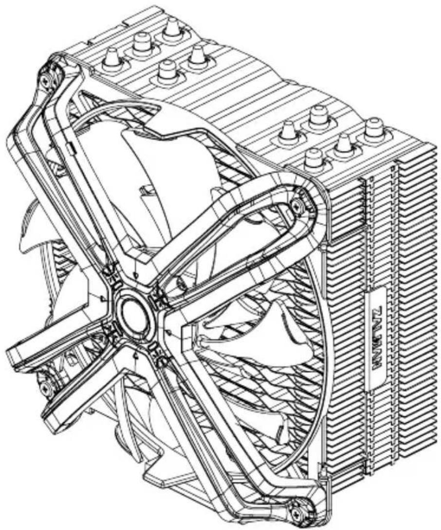
natural_image
Technical line drawing of a mechanical fan assembly with cooling fins and heat exchangers (no text or symbols)Latest Intel & AMD Compatible
Intel Socket LGA2066/2011-V3/2011/115X CPUs
AMD Socket AM4/AM3+/AM3 CPUs

Developed and designed by ZALMAN in Korea.
This product is protected by ZALMAN's pending or registered patents.

www.zalman.com
* To ensure safe and easy installation, please read the following precaution.
* Product design and specifications may be revised to improve quality and performance without notice.
Precautions
English
■ Avoid tempering with objects or hands into the fan while it is in operation to prevent product damage and injuries.
■ Do not eat the thermal grease, and avoid its contact with skin and eyes. If contact is made with skin, wash off with water. If irritation persists, seek medical attention.
■ To prevent possible injuries, gloves must be worn while handling this product.
■ Excessive force exerted on the fan may cause damage to the fan and/or system.
■ Use and keep product away from reach of children.
- Check the components list and condition of the product before installation. If any problem is found, contact the retailer to obtain a replacement.
- Our company assumes no responsibility for any problem that occurs due to the use of the product for purposes other than its designated purposes and/or the carelessness of the consumer.
■ Zalman Tech Co., Ltd. Is not responsible for any damages due to overclocking CPU such as, CPU and system components.
■ During transportation of the system, the cooler must be removed. Zalman Tech Co., Ltd. is not responsible for any damages that occur during the transport of a system.
■ Product design and specifications may be changed to improve quality and performance without notice.
Précautions
Français
natural_image
Technical line drawing of a four-blade fan assembly with 140mm dimension label (no text or symbols beyond measurement)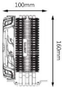
Components
 |  | 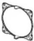 | 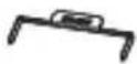 | 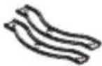 | 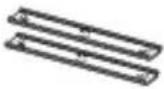 |
| Cooler | Fan Fan Clips Fan Guides | AMD Guide | Intel Guide | ||


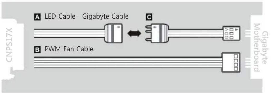
Gigabyte Cable
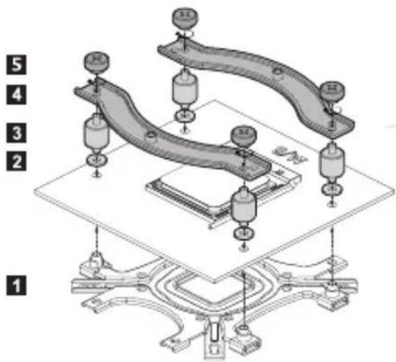
Nuts
Fan Screws
Thermal Compound
Backplate
Loading Block (Intel)
Loading Block (AMD)
Manual
Side Caps

Fixing Bolts
Stand-off Nuts
Standoffs(A)
115X / AM3 / AM4
Standoffs(B)
2066/2011-V3/2011
Washers
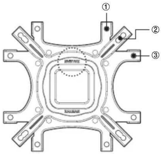
INTEL, AMD Backplate
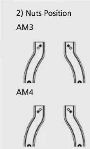
1) Nuts Position
natural_image
Technical line drawing of a mechanical bracket or frame structure (no text or symbols)
Caution
Please check the proper ZALMAN logo direction on backplate for each Intel and AMD socket.
No backplate is necessary for Intel LGA2066/2011-V/2011 socket.

natural_image
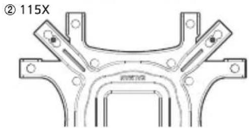
Technical line drawing of a mechanical bracket component (no text or symbols)2) 115X
natural_image
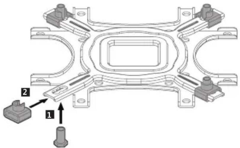
Mechanical assembly diagram showing a bracket with two parts and directional arrows indicating motion (no text or symbols)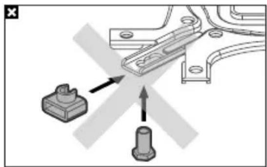
natural_image
Mechanical assembly diagram showing a bracket with two parts, one with an arrow indicating direction (no text or symbols)3) AM3
natural_image
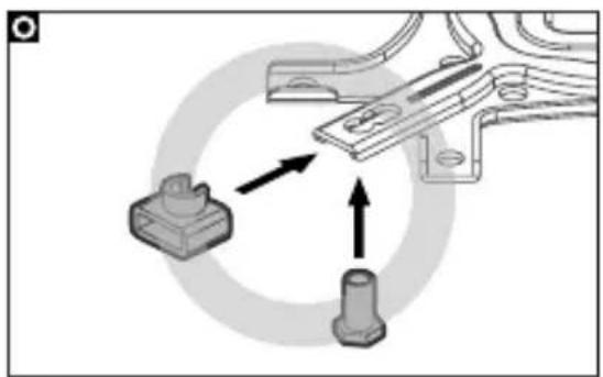
Mechanical assembly diagram showing a clamp and pin attachment with directional arrows (no text or symbols)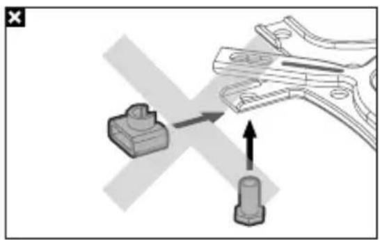
natural_image
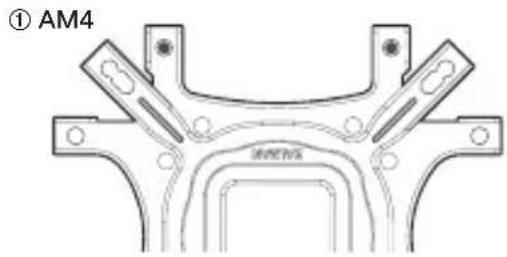
Mechanical assembly diagram showing a clamp tool interacting with a connector (no text or symbols present)4) AM4
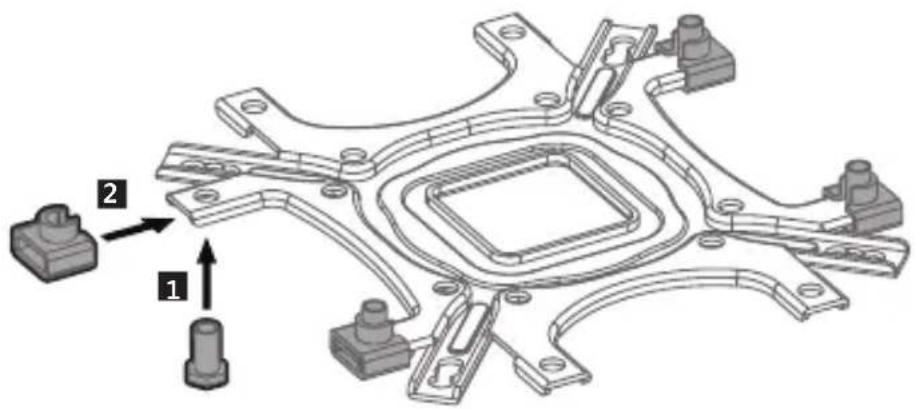
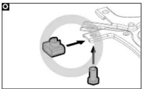
natural_image
Mechanical assembly diagram showing a clamp tool interacting with a component, with no visible text or symbols.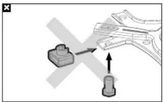
natural_image
Diagram showing a mechanical component being inserted into a clamped part, with no visible text or symbols.
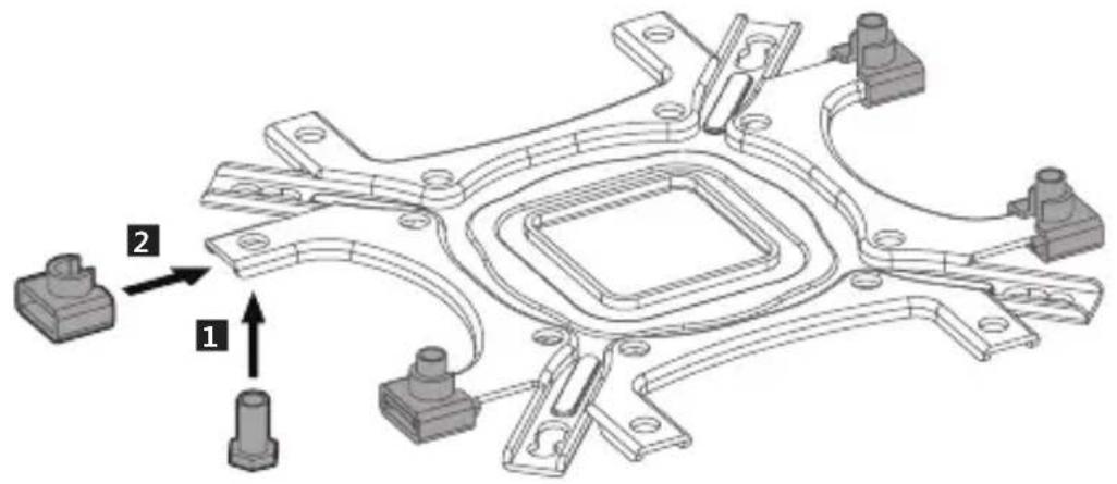
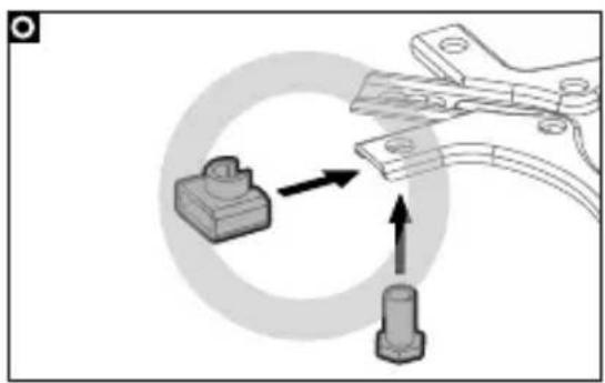
Caution
Take note of the orientation of the nuts and the side caps.
INTEL, AMD Loading Block
1) Intel 2) AMD
Loading Block(Intel)
Loading Block(AN)
natural_image
Mechanical assembly diagram showing a central component with surrounding components (no text or symbols)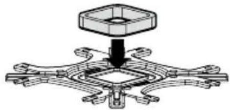
natural_image
Mechanical assembly diagram showing a central hub with surrounding components (no text or symbols)
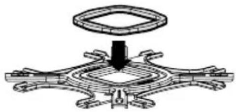
Caution
Remove the tape cover of loading block and attach it to the backplate.
1. Intel Users
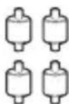
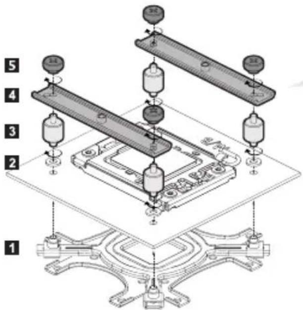
1) LGA2066 / 2011-V3 / 2011

Stand-offs(B)

Intel Guide Stand-off Nuts
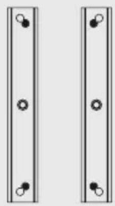
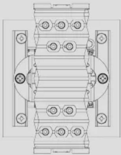
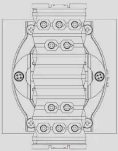
2) Nuts Position
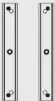
natural_image
Two identical vertical panels with circular holes, no text or symbols present
Caution
Backplate is not needed for LGA2066 / 2011-V3 / 2011 sockets.
4

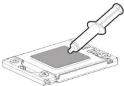
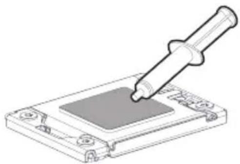
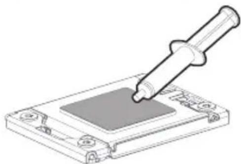
Thermal Compound
natural_image
Illustration of a pipette dispensing liquid into a microchip (no text or symbols)5
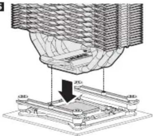
natural_image
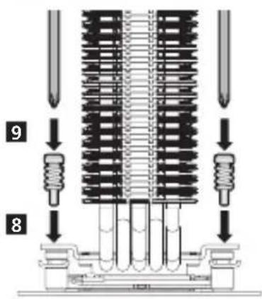
Technical diagram of a mechanical assembly with a downward arrow indicating a process or operation (no text or symbols present)
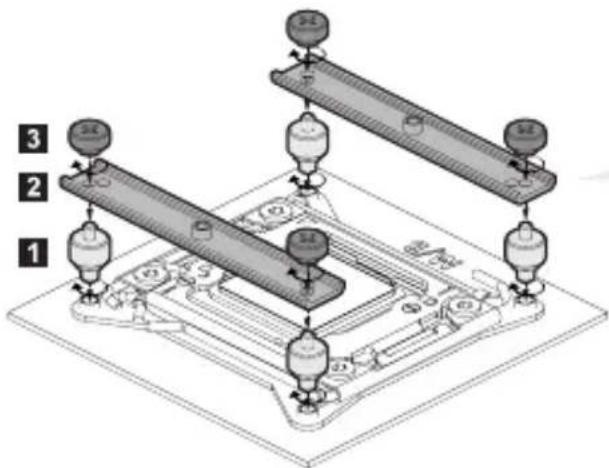
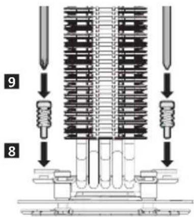
Fixing Bolts
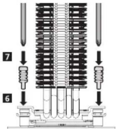

Caution
Screw-in both bolts in an alternating fashion until they are completely tightened.
Detail Image
natural_image
Technical line drawing of a mechanical assembly with bolt holes and mounting brackets (no text or symbols)8

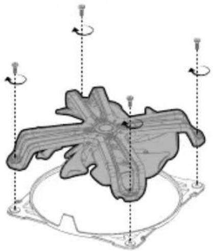
Fan Screws Fan Guide
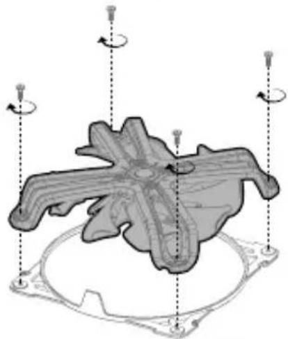
natural_image
3D mechanical component diagram with rotational arrows indicating motion, no text or symbols present9
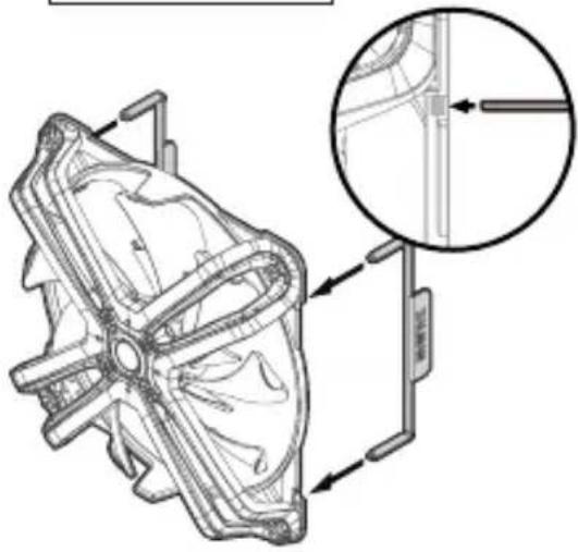
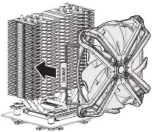
Fan Clips
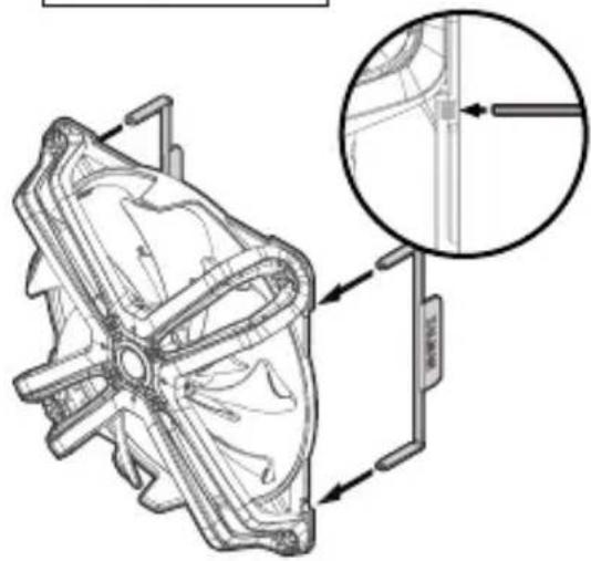
natural_image
Technical line drawing of a mechanical component with an inset magnified detail (no text or symbols)10
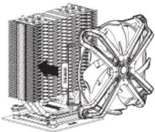
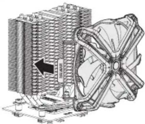
natural_image
Technical illustration of a computer cooling unit with visible cooling fan and cooling tower (no text or symbols)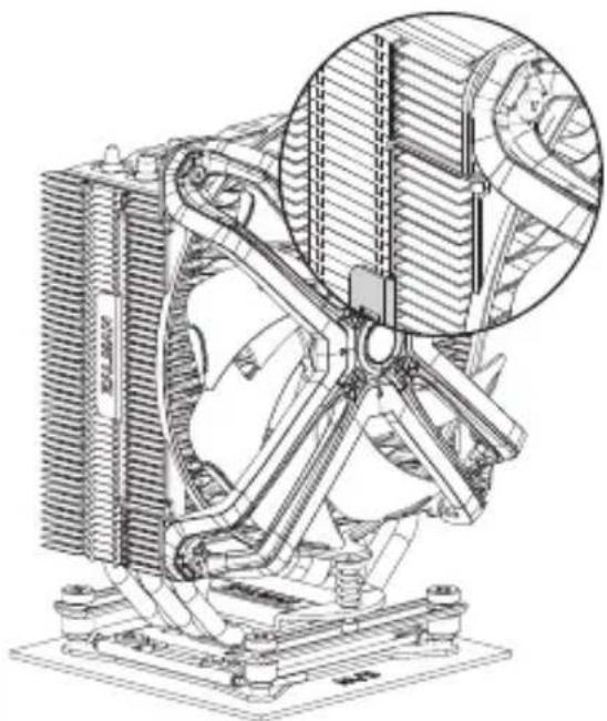
natural_image
Technical line drawing of a mechanical cooling fan assembly with visible cooling fins and heat dissipation (no text or symbols)
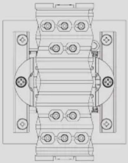
Caution
Please install Fan in the center of the heat sink for maximum performance in case of no interference of RAM.
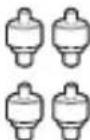
2)115X

3) Nuts Position
natural_image
Two identical vertical panels with circular holes, no text or symbols present
natural_image
Technical line drawing of a mechanical component with a pipette inserted into a square slot (no text or symbols)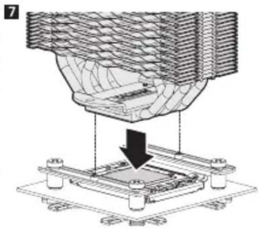
natural_image
Technical diagram showing a mechanical assembly with a downward arrow indicating a process (no text or symbols present)
Detail Image
natural_image
Technical line drawing of a mechanical assembly with bolt holes and housing (no text or symbols)
Caution
Screw-in both bolts in an alternating fashion until they are completely tightened.
10

Fan Screws Fan Guide

natural_image
3D mechanical component diagram with rotational arrows indicating motion, no text or symbols present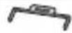
Fan Clips
natural_image
Technical line drawing of a mechanical component with an inset magnified detail (no text or symbols)12
natural_image
Technical illustration of a computer cooling system with cooling fan and cooling tower (no text or symbols)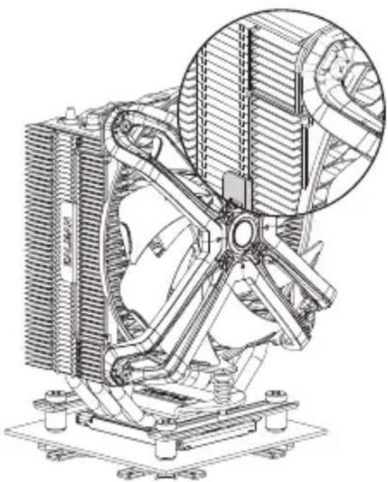
natural_image
Technical line drawing of a mechanical fan assembly with cooling fins and heat exchangers (no text or symbols)
Caution
Please install Fan in the center of the heat sink for maximum performance in case of no interference of RAM.
2. AMD Users
1) AM3 / AM4


Caution
Please be cautious for the direction of AMD Guide installation.
natural_image
Technical line drawing of a pipette dispensing liquid onto a microchip (no text or symbols)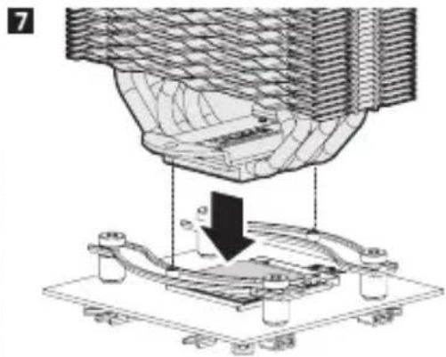
natural_image
Technical diagram of a mechanical assembly with a downward arrow indicating a process (no text or symbols present)Fixing Bolts
Detail Image
natural_image
Technical line drawing of a mechanical component with multiple bolt holes and internal channels (no text or symbols)
Caution
Screw-in both bolts in an alternating fashion until they are completely tightened.
10

Fan Screws Fan Guide
natural_image
3D mechanical component diagram with rotational arrows indicating motion, no text or symbols present
Fan Clips

natural_image
Technical line drawing of a mechanical component with an inset magnified detail (no text or symbols)12
natural_image
Technical illustration of a computer cooling system with cooling fan and cooling tower (no text or symbols)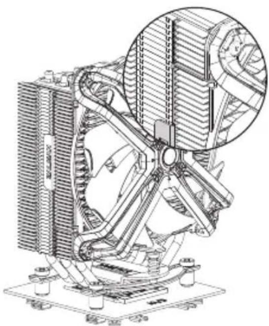
natural_image
Technical line drawing of a mechanical cooling fan assembly (no text or symbols)
Caution
Please install Fan in the center of the heat sink for maximum performance in case of no interference of RAM.
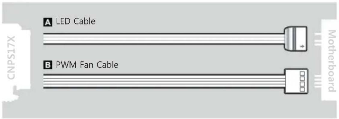
3. Cable Connection
1) Connection to other motherboards
2) Connection to Gigabyte motherboards
- Fan Specifications
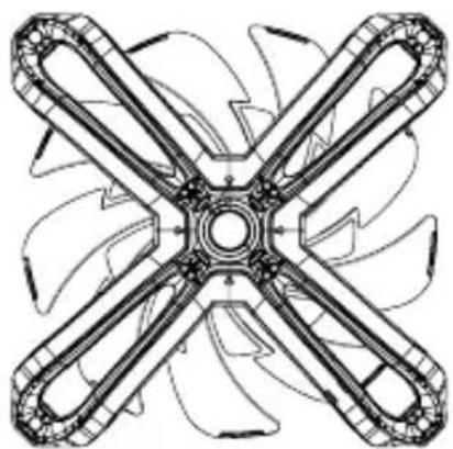
natural_image
Technical line drawing of a four-blade fan or impeller assembly (no text or symbols)Dimensions: 140 x 140 x 26(H)mm
Speed: 800 \~ 1,500 ± 10% RPM
Max Noise Level: 29 dB(A) ±10%
Bearing Type : FDB (Fluid Dynamic Bearing)
Max Airflow : 61 CFM ±10%
Pin Connector : 4-Pin (PWM),
3-Pin (Addressable)
Rated Voltage: 5\~12 V DC
제품 보증서
This mark, designed by Zalman, indicates product compliance with the European Union's RoHS (Restriction of Hazardous Substances) Directive.

Disposal of Old Electrical & Electronic Equipment (Applicable in the European Union and other European countries with separate collection systems)
Memo
Memo
ZALMAN
COOL INNOVATIONS
www.zalman.com

Brand : ZALMAN
Model : CNPS17X
Category : Computer cooling system