EWAD350D-XR - Air Conditioning DAIKIN - Free user manual and instructions
Find the device manual for free EWAD350D-XR DAIKIN in PDF.


User questions about EWAD350D-XR DAIKIN
0 question about this device. Answer the ones you know or ask your own.
Ask a new question about this device
Download the instructions for your Air Conditioning in PDF format for free! Find your manual EWAD350D-XR - DAIKIN and take your electronic device back in hand. On this page are published all the documents necessary for the use of your device. EWAD350D-XR by DAIKIN.
USER MANUAL EWAD350D-XR DAIKIN
Installation, Operation and Maintenance Manual D-EIMAC00208-16EU
Air-cooled chiller
EWAD\~D-S* 180 ÷ 580
EWAD\~D-X* 240 ÷ 620
EWAD\~D-H* 200 ÷ 590
Refrigerant: R-134a
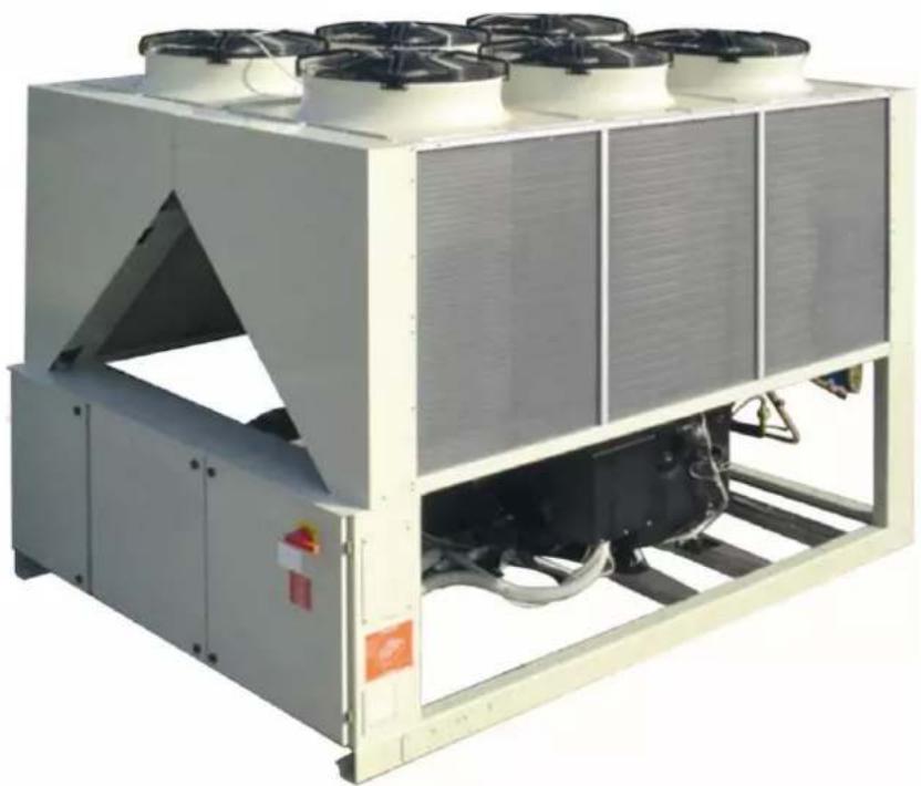
natural_image
Industrial cooling unit with heat exchangers and cooling fans (no visible text or symbols)
| English | 12 |
| Deutsch | 21 |
| Français | 30 |
| Nederlands | 39 |
| Español | 48 |
| Italiano | 57 |
| Ελληνικά | 66 |
| Português | 75 |
| Русский | 84 |
| Swedish | 93 |
| Norsk | 102 |
| Finnish (Suomi) | 111 |
| Polski | 120 |
| Čech | 129 |
| Hrvat | 138 |
| Magyar | 147 |
| Român | 156 |
| Slovenski | 165 |
| Български | 174 |
| Slovenský | 183 |
English language: Original Instructions
All other language: Translation of the Original Instructions
A - Piping diagram for not economised unit ; B - Piping diagram for economised unit (pictures show one circuit only even if units have two circuits)
flowchart
graph TD
    A[" Tank ⑤ "] --> B[" Valve ⑧ "]
    B --> C[" Control Unit ⑨ "]
    C --> D[" Valve ⑪ "]
    D --> E[" Control Unit ⑭ "]
    E --> F[" Valve ⑫ "]
    F --> G[" Control Unit ⑮ "]
    G --> H[" Valve ⑬ "]
    H --> I[" Control Unit ⑰ "]
    I --> J[" Valve ⑭ "]
    J --> K[" Control Unit ⑱ "]
    K --> L[" Valve ⑮ "]
    L --> M[" Control Unit ⑰ "]
    M --> N[" Valve ⑦ "]
    N --> O[" Control Unit ⑤ "]
    O --> P[" Valve ⑥ "]
    P --> Q[" Control Unit ④ "]
    Q --> R[" Valve ③ "]
    R --> S[" Control Unit ② "]
    S --> T[" Valve ① "]
    T --> U[" Control Unit ①6"]
    U --> V[" Valve ⑩ "]
    V --> W[" Control Unit ⑩ "]
    W --> X[" Valve ⑪ "]
    X --> Y[" Control Unit ⑯ "]
    Y --> Z[" Valve ⑬ "]
A
B

flowchart
graph TD
    A["①"] --> B["②"]
    B --> C["③"]
    C --> D["④"]
    D --> E["⑤"]
    E --> F["⑥"]
    F --> G["⑦"]
    G --> H["⑧"]
    H --> I["⑨"]
    I --> J["⑩"]
    J --> K["⑪"]
    K --> L["⑫"]
    L --> M["⑬"]
    M --> N["⑭"]
    N --> O["⑮"]
    O --> P["⑯"]
    P --> Q["⑰"]
    Q --> R["⑱"]
    R --> S["⑲"]
    S --> T["⑳"]
    T --> U["㉑"]
    U --> V["㉒"]
    V --> W["㉓"]
    W --> X["㉔"]
    X --> Y["㉕"]
    Y --> Z["㉖"]
    Z --> A
    style A fill:#f9f,stroke:#333
    style B fill:#f9f,stroke:#333
    style C fill:#f9f,stroke:#333
    style D fill:#f9f,stroke:#333
    style E fill:#f9f,stroke:#333
    style F fill:#f9f,stroke:#333
    style G fill:#f9f,stroke:#333
    style H fill:#f9f,stroke:#333
    style I fill:#f9f,stroke:#333
    style J fill:#f9f,stroke:#333
    style K fill:#f9f,stroke:#333
    style L fill:#f9f,stroke:#333
    style M fill:#f9f,stroke:#333
    style N fill:#f9f,stroke:#333
    style O fill:#f9f,stroke:#333
    style P fill:#f9f,stroke:#333
    style Q fill:#f9f,stroke:#333
    style R fill:#f9f,stroke:#333
    style S fill:#f9f,stroke:#333
    style T fill:#f9f,stroke:#333
    style U fill:#f9f,stroke:#333
    style V fill:#f9f,stroke:#333
    style W fill:#f9f,stroke:#333
    style X fill:#f9f,stroke:#333
    style Y fill:#f9f,stroke:#333
    style Z fill:#f9f,stroke:#333
D-EIMAC00208-16EU - 3/192
| English | Deutsch | Français | Nederlands | Español | Italiano | |
| 1. | Compressor | Vardichter | Compresseur | Compressor | Compresor | Compressore |
| 2. | Non-return valve | Rückschlagventil | Clapet de non retour | Terugslagklep | Valvula de no retorno | Valvola di non ritorno |
| 3. | Discharge shutoff valve | Vorlaufabsperventil | Robinet de refoulement | Persafslutier | Grito de salida | Rubinetto di mandata |
| 4. | High-pressure safety valve | Hochdruck-Sicherheitsventil | Soupape de sécurité haute pression | Veiligheidsklep hoge druk | Valvula de seguridad de alta presión | Valvola di sicurezza alta pressione |
| 5. | Condenser coil | Verlüssigerregister | Batterie à condensation | Condensorgroep | Bateria condensadora | Batteria condensante |
| 6. | Subcooling section | Unterkühlungssektion | Section de sous-refroidissement | Onderkoelingsectie | Sección de subenfriamiento | Sezione di sottorafriedamento |
| 7. | Axial ventilator | Axialventilator | Ventilateur axial | Axiale ventilator | Ventilador axial | Ventilatore assiale |
| 8. | Liquid line isolating valve | Absperventil Flüssigkeitsleitung | Vanne d'isolement de la ligne du liquide | Atsluter vloeistoflijn | Valvula de corne de la línea del líquido | Valvola isolante línea del líquido |
| 9. | Dehydration filter | Entwässerungssfilter | Filtre déshydrateur | Dehydratatiefilter | Filtro deshidratador | Filtro deidratatore |
| 10. | Liquid and humidity indicator | Flüssigkeits- und Feuchtigkeitsanzeige | Indicateur de liquide et humidité | Vloeistof- en vochtigheidsindicator | Indicador de líquido y humedad | Indicatore di líquido e umidità |
| 11. | Electronic expansion valve | Elektronisches Expansionsventil | Détendeur électronique | Elektronisch expansieventiel | Valvula de expansión electrónica | Valvola di espansione elettronica |
| 12. | Liquid injection solenoid valve | Solenoidventil zur Flüssigkeitselinspritzung | Vanne solénolde pour injection du liquide | Magneetklep voor vloeistofinjectie | Valvula solenoïde para inyección de líquido | Valvola solenoïde per iniezione di líquido |
| 13. | Evaporator | Verdampfer | Evaporateur | Verdamper | Evaporador | Evaporatore |
| 14. | Low-pressure safety valve | Niederdruck-Sicherheitsventil | Soupape de sécurité à basse pression | Veiligheidsklep lage druk | Valvula de seguridad de baja presión | Valvola di sicurezza a bassa pressione |
| 15. | Suction shutoff valve | Absperventil Saugleitung | Robinet d'aspiration | Aanzuiging afsluitklep | Grito de aspiración | Rubinetto di aspirazione |
| 16. | Service port | Wartungsklappe | Port de maintenance | Dienstluikje | Portillo para asistencia | Portello per assistenza |
| 17. | Water outlet connection | Anschluss Wasserauslauf | Connexion sortie eau | Aansluiting uitgang water | Conexión de la salida de agua | Connessione uscita acqua |
| 18. | Water inlet connection | Anschluss Wasserzulauf | Connexion entrée eau | Aansluiting ingang water | Conexión de la entrada de agua | Connessione ingresso acqua |
| 19. | Economiser | Economiser | Economiseur | Economiser | Economizador | Economizzatore |
| 20. | Economiser solenoid valve | Solenoidventil Economiser | Vanne solénolde économiseur | Magneetklep economiser | Valvula solenoïde economizador | Valvola solenoïde economizzatore |
| 21. | Economiser thermostatic expansion valve | Thermostatisches Expansionsventil Economiser | Détendeur thermostatique économiseur | Thermostatisch expansieventiel economiser | Valvula de expansión termostática del economizador | Valvola di espansione termostática economizzatore |
| ST1 | Suction temperature probe | Ansaugtemperaturfühler | Sonde de température aspiration | Temperatuursonde aanzuiging | Sonda de temperatura en aspiración | Sonda temperatura aspirazione |
| WL1 | Low-pressure transducer | Niederdrucksensor | Transducteur basse pression | Omzetter lage druk | Transductor de baja presión | Trasduttore bassa pressione |
| WO1. | Oil pressure transducer | Öldrucksensor | transducteur pression de l'huile | Omzetter oliedruk | Transductor de presión del aceite | Trasduttore pressione olio |
| WH1. | High-pressure transducer | Hochdrucksensor | Transducteur haute pression | Omzetter hoge druk | Transductor de alta presión | Trasduttore alta pressione |
| WD1. | Discharge temperature sensor/Oil | Öl'Auslasstemperaturfühler | Huile/capteur température de vidange | Olie/sensor uitaattemperatuur | Aceite/sensor de temperatura do descarga | Olio/sensore temperatura di scarico |
| F13. | High-pressure pressure switch | Maximum-Druckwächter | Pressostat haute pression | Drukregelaar hoge druk | Presostato de alta presión | Pressostato alta pressione |
| WIE. | Water entering temperature probe | Temperaturfühler Wasserzulauf | Sonde de température entrée eau | Temperatuursonde watertoevoer | Sonda de temperatura de entrada del agua | Sonda temperatura ingresso acqua |
| WOE. | Water leaving temperature probe | Temperaturfühler Wasserauslauf | Sonde de température sortie eau | Temperatuursonde waterutlaal | Sonda de temperatura de salida del agua | Sonda temperatura uscita acqua |
D-EIMAC00208-16EU - 4/192
| Ελληνικά | Português | Русский | Swedish | Norsk | Finnish | Polyskk | Čech | |
| 1. | Συμπεστής | Compressor | Kompressor | Kompressor | Kompressor | Kompressor | Sprezka | Kompressor |
| 2. | Βαλβίδα εξέγχου | Válvula de não retorno | Обратный клапан | Backventil | Tilbakaslageventil | Takalakuventil | Zawór zwotny | Zoetný ventil |
| 3. | Στρόφγωτα ροης | Tomaira de mandacia | Отсечий клапан на навнетении | Tryckavstängningsventil | Avstongningsventil på utlop | Poaton tyhönysventil | Zawór tloczny | Vytačný kohoutek |
| 4. | Предохранительный клапан по высокому давлению | Sikkorhetsventil for høytryk | Korkeapalno turvaventilii | Zawór berpexceriška wysokiego cisténia | Bezpefinčinski ventil vyskeho ilaku | |||
| 5. | Μπαταρία συμπικόνουσης | Balería condensante | Конденсатор | Kondensor | Kondensatorbatteri | Jäðhydlysikierukka | Wężownica skraplasza | Konderzačni balerie |
| 6. | Τμήτα subseding | Sarcção de subarrefecimento | Секции перекохлаждения | Underkiylningssekion | Underkiylningsekjon | Alijáshdylyksen osa | Sekcja dochizdania | Čast podchiarovac. zařizani |
| 7. | Ανιμπτηρας οξενα | Vorríador axili | Οσοῦν betaπιτορ | Axialtäkt | Axialtevintilator | Akisaiulpuhailln | Wentylator oscwy | Axitini ventilátor |
| 8. | Βαλβίδα μονωσης γρομρής υγρού | Válvula isolante da linha do liquido | Отсечий клапан підравлической линии | Isolertingsventil vätskeledning | Avstongningsventil på fyrlende inje | Nastolinjan erlasyenventilii | Zawór odcinajcy fliŋę plynu | Izolačni kohoutek line kapaliny |
| 9. | Φίλιρο αρύγρανσης | Filtro desirator | Фильтр осушитель | Avfuktingsfiller | Avfuktingsfiller | Kuvaussusdaslin | Filtr odwudniaca | Filtr dehydrátoru |
| 10. | Δεκτης υγρού και υγρασιας | Indicator de liquido e humicade | Индикатор навжности | Välske- och fulkivisare | Vaske-o- och fulkignetsseglass | Neste- ja kosteusmitari | Wskažnik plynu i wilgoci | Ukazatel kapallny a vihkostil |
| 11. | Βαλβίδα πλεκτρονικής επέκτασης | Válvula de expansão eletránica | Электронный расширительный клапан | Elektronisk expansionssvenil | Elektronisk ekspanjonsvenil | Elektroninon pisunlaventilii | Elektroniczny zawór raspřejny | Expanzni elektronický ventil |
| 12. | Συληνοειδής βαλβίδα γικ την έχχυση υγρού | Válvula solonódo para injęcia de liquido | Соленидный клапан впрькования хидости | Magnetventil för vätskeijnjocring | Magnetventil för væskeinjeksjon | Solonidvontilii nesteriskutuksen | Zawór elektronagnotyczny wryskiwania plynu | Solonirolní ventil pro vestifikováni kapaliny |
| 13. | Εξαριστής | Evaporador | Испаратiver | Förångare | Evaporator | Höyrystin | Parownik | Evaporátor |
| 14. | Βαλβίδα ασφολείας χουμής πίεσης | Válvula de segurança a baixa pressão | Предохранительный клапан по низаку давлению | Lągtryoka sákerhetaventi | Sikkorhetsventil for lavtrykk | Matalapašno turvaventilii | Zawór bezpexceriška niskiego cisténia | Bezpefinčinski ventil nizčko tlaku |
| 15. | Βροση αναρρόφησης | Tomaira de aspiração | Отсечий клапан на васаевании | Sugavstängningsventil | Avstongningsventil på inlop | Imuhena | Zawór asswny | Nasavoi kohoutek |
| 16. | Πόρτα βολθευος | Porta para assistência | Смутровой пок | Servicelucka | Serviceluke | Huotoluukku | Drzwiczki serwisowe | Servisni dvifka |
| 17. | Συδεση εξδου νερού | Conexão para saída ao água | Выход воды | Anslutning vallenulapp | Forbindelse for vanmullop | Veden ulostulilillos | Podłączenie odpływu wody | Zapojení vyslup vody |
| 18. | Συνεση αὐδου νερού | Conexão para entrada de água | Вход воды | Anslutning vattenulloop | Forcinolase for vermillep | Veden sisäänmanilitos | Podłączenie odpływu wody | Zapojení vestup vody |
| 19. | Μονάδα εξοκανόμησεις ενέργωσις | Economizador | Экономайзер | Kyrling | Fedevannaforvarmer | Säästýykiskő | Ekonomízer | Ekonomizátor |
| 20. | Συληνοειδής βαλβίδα ρονάδος εξοκανόμησεις ενέργωσις | Válvula solonódo economizandor | Соленидный клапан эккономайзера | Magnelventil kyrling | Magnetventil for fadevansforvarmer | Säästýykiskón sclenoidaventilii | Elekstromagnétyczny zawór ekonomizera | Sosonirolní ventil ekonomizátoru |
| 21. | Βαλβίδα θερμοσταπικής επέκτασης εξοκανόμησεις ενέργωσις | Válvula de expansão temostática do economizador | Термостатический расширительный клапан эккономайзера | Termostatisk expansionssvenil for lyrling | Termostatisk ekspanjonsvenil for fadevansforvarmer | Säästýykiskón termostactition pisunlaventilii | Termostatyczny zawór raspřejny ekonomizera | Tepelný expanzni ventil ekonomizátoru |
| ST1 | Ανδητήρας αναρρόφησης θερμοκρασίας | Sonda da temperatura de aspiração | Датчик температуры на насосвании | Sond sugtomperatur | Temporaturfolor i innlop | Imun lämpõltila-anturi | Sonda temperatury zarysania | Tepelná sonda nasávání |
| WLI | Μετοροπέσας χουμής πίεσης | Transistor do baixa pressão | Датчик NEGROD давления | Lągtryksomvandlare | Lavrykksomformer | Matalapaineantur | Przetwomik niskogo cisténia | Transduktor nizčko tlaku |
| WO1. | Μετοροπέσας πίεσης λοδίου | Transistor de pressão do doro | Датчик давления насла | Ojotrycksomvandlare | Ojotrykkomformor | Öljypainoanturi | Przetwomik cisténia oleju | Transduktor tlaku dieje |
| VIH1. | Μετοροπέσας χυμής πίεσης | Transistor de alta pressão | Датчик высокого давления | Høgtryksomvandlare | Høytrykksomformer | Korwaapaineanturi | Przetwomik wysokiego cisténia | Transduktor vysokého tlaku |
| WD1. | Αλδιναθυθήρα εξόδου θερμοκρασίας | Oblo/sensor temperature da descarga | Датчик температуры масла на навнетении | Utsäpsoptemperatursenso r'Olja | Utdadtemperatur sensorolite | Poospämpätilan öllyarturi | Ölcipczujnik temperatury oprówadzania | Ölji/senzor tepłaty na odvodu |
| F13. | Σδοτημε ρόρματης χυμής πίεσης | Presadato alta pressão | Реле высокого давления | Høgtryksamlare | Høytrykkspressostat | Korkeapaire kytkin | Prosostat wysokogo cisténia | Prescelat vysokého tlaku |
| WIE. | Ανδητήρας δερμεκροσίας εξόδου νερού | Sonda da temperatura da entrada da água | Датчик температуры воды на выходе | Temporaturson lilloppsvaton | Temporaturfolor for vann i inngang | Voden sisäänmoni lämpõltila-anturi | Sonda temperatury dopływu wody | Topolná sonda vestup vody |
| WOE. | Ανδητήρας δερμεκροσίας εξόδου νερούHrvat | Sonda da temperatura da salsa da águaMagyar | Датчик температуры воды на выходеRomân | Temporaturson lilloppsvatonSlovenski | Temporaturfolor for vann i utgangБългарски | Ulostulevan vesen lämpõtle-anturiSlovenský | Sonda temperatury dopływu wody | Tapelná sonda vestup vody |
| 1. | Kompresor | Kompresszor | Compresor | Kompresor | Kompresor | Kompresor | ||
| 2. | Ventil za spriječavanje vraćanja | Visazosacó szelep | Valvá undirecjónsá | Napovratni ventil | Задържеш клапан | Spstiny ventil | ||
| 3. | Ulazna slavina | Botoly olizro ceap | Robinet ovecuaro | Ovodni ventil | Kran za podavené | Vytadný kohútk | ||
| 4. | Sigurnosni ventil visoki pritisak | Biztonsági szolop nagy nyomás | Valvá de siguranja inaltá prestune | Vlasokotáni varnostni ventil | Preplazen klalan i valcojo налягане | Bezpečnostný ventil vysokého tlaku | ||
| 5. | Kondenzacijska balerija | Kondenzád egyseg | Baterle de condensare | Kondenzacijsko navilje | Kondenoiraša Bateriia | Kondenzatná baléria | ||
| 6. | Sekcija za podrashladivanje | Tūhlūl ęgysstg | Secijune de subrádire | Podihajeni del | Modyi za sarjyoxiknjdane | Caste podrhizovec, zastedonia | ||
| 7. | Akoljali ventilator | Tengelyirányi ventilator | Ventilator axial | Aksialni ventilator | Bentilatori za invekndane | Aktálny ventilator | ||
| 8. | Izolacijski ventil linija tekučine | Folydek izolitó szelep | Valvá izolare line de lichid | Izolacijski ventil lekočinske linije | Izolinirati klalan liniku na technosta | Izolačný kohútk linie kvapalny | ||
| 9. | Fitar za odstranjivanje vlage | Vizelenitó əzɪð | Filtru doshidrator | Sušini filter | Декидиращ фильтр | Fitar denydrátors | ||
| 10. | Indikator tekučine i vlažnosti | Polydek és nedvesség mutalo | Indicator de lichid și uniditate | Indikator tekočine in vlage | Индикатор за техност и влажност | Ukazovalet kvapalny a vlnkosti | ||
| 11. | Ventil elektronske ekspanzije | Elektronski szabelyozoszelep | Valvá de expansiune electronică | Elektronski ekspanzijski ventil | Klalani za електронно разширение | Expanzný elektronický ventil | ||
| 12. | Ventil selenoidi za ubrigzavanje tekucine | Folydek beřeskendező szelenoidi szelep | Valvá solenoidă pentru linyedja lichidului | Elekromagneti ventil za vžirzig tekočine | Klalani zapredanje za инжетиряке на техност | Solcnodný ventil pre vystrekovanje kvapalny | ||
| 13. | Ispartivač | Párologtató | Vaporizator | Izparlinik | Изолатор | Evaporátor | ||
| 14. | Sigurnosni ventil na niskom pritisku | Biztonsági szolop alacosony nyomás | Valvá de siguranja jossá prestune | Nizkatlačni varmodni ventil | Preplazen klalan za nisko налягане | Bezpečnostný ventil nizkeho tlaku | ||
| 15. | Usana slavina | Elziví vá zárcsap | Robinet de aspiratje | Sesalni ventil | Kran za засмукване | Nasívoci kohútk | ||
| 16. | Vratašca za servisiranje | Szerviz ajtó | Uspá pentru asistenja | Servisa vrata | Обслужащ лек | Servisno dvorka | ||
| 17. | Prijučak izlaz voce | Vizleeresztó csatlakozás | Conexiune legire apá | Prijuček za odvod vode | Вська изход вода | Zapovena vystup vody | ||
| 18. | Prijučak izlaz voce | Viz bomončni csatlakozás | Conexiune inflare apá | Prijuček za dovod vode | Вська вход вода | Zapocono vistu vody | ||
| 19. | Ekonomizator | Eklhūló (economiser) szelenoidi szelep | Economizor | Gránik | Толпосоменник | Ekonomizator | ||
| 20. | Ventil selenoidi ekonomizator | Eklhūló (economiser) szelenoidi szelep | Valvá solenoidá economizor | Magnetotemični ventil grehika | Klalani zapredanje tollpoobemnik | Solcnodný ventil ekonomizatora | ||
| 21. | Ventil za termostalčku ekspanziju okonomizatora | Eklhūló (economiser) hőszablyezó szeloc | Valvá de expansiune termostalča economizor | Termostalčki ekspanzljaki ventil grínika | Klalani термостатинно разширение tollpoobemnik | Terpiny exprenzný ventil okonomizatora | ||
| ST1 | Temperstuma sonda usisa | Elsztivali hőnéréskletnérő szonda | Soná de temperaturá aspratje | Soná temperature v sosalom tomokogu | Temperaturna conda za zakouvanje | Topolná sonda nasáventa | ||
| WL1 | Transduktor nizak pritisak | Kis nyomás transzduktor | Traductor preslune jossá | Nizkatlačni prevornik | Konвертор низко налогане | Transduktor nizkeho tlaku | ||
| WO1. | Transduktor pritsak tlaka | Orajnyomas transzduktor | Traductor preslune ulsi | Prevornik ojinega taka | Konвертор налягане на маслото | Transduktor taku ovja | ||
| WH1. | Transduktor visoki pritisak | Nagy nyomás transzduktor | Traductor inaltá prestune | Vlasokotlačni prevornik | Konвертор высоко налягане | Transduktor vysokého tlaku | ||
| WD1. | Ulje/sonzor temperatura odsisa | Olaj’kimeneti hőnérésklet érzekető | Ulei’ senzor temperaturá evacuare | Oljsenzor odvodne temperatur | Масилсензор температура на отвеждане | Olcy/sonzor tepioty na odvode | ||
| F13. | Mjerač priliska visoki pritisak | Nagy nyomás nyomáskapcsolá | Presostat inaltá prestune | Vlasokotačni presostat | Контактос ограничител високо налягане | Presostat vysokého tlaku | ||
| WIE. | Temperatura sonda izlaz vode | Bemeneti vizhőmérséket mérő szonda | Sondi temperaturá apá intrare | Sonda temperature vhodne vode | Temperaturana conda вход вода | Teplná sonda vstup vody | ||
| WOE. | Temporstuma sonda izlaz vode | Kimeneti vizhőmérséket mérő szonda | Sondá temperaturá apá isjere | Sonda temperaturó izhodno vodo | Temperaturna conda изход вода | Topolná sonda vstup vody |
D-EIMAC00208-16EU - 6/192
A - Piping diagram for not economised unit with heat recovery ; B - Piping diagram for economised unit with heat recovery (pictures show one circuit only even if units have two circuits)
A – Hydraulikschaltbild für Einheiten ohne Economiser mit Wärmerückgewinnung; B - Hydraulikschaltbild für Einheiten mit Economiser und Wärmerückgewinnung (die Bilder zeigen nur einen Kreislauf, tatsächlich besitzen die Einheiten jedoch zwei Kreisläufe)
A – Schéma hydraulique pour unité sans économiseur avec récupération de chaleur; B - Schéma hydraulique pour unité avec économiseur et récupération de chaleur (les images représentent un seul circuit, mais les unités comporte en réalité deux cirucuits)
A – Hydraulisch schema voor groep zonder economiser met warmterecuperatie; B - Hydraulisch schema voor groep met economiser en warmterecuperatie (de afbeeldingen tonen een enkel circuit, maar in werkelijkheid zijn de groepen uitgerust met twee circuits)
A - Esquema hidráulico para unidades sin economizador con recuperador de calor; B - Esquema hidráulico para unidades con economizador y recuperador de calor (las imágenes muestran un solo circuito, pero en realidad las unidades tienen dos)
A – Schema idraulico per unità senza economizzatore con recupero di calore; B - Schema idraulico per unità con economizzatore e recupero di calore (le immagini mostrano un solo circuito, ma in realtà le unità sono dotate di due circuiti)
Α – Υδραυλικό διάγραμμα για μονάδες χωρίς σύστημα εξοικονόμησης ενέργειας με ανάκτηση θερμότητας, Β - Υδραυλικό σχεδιάγραμμα για μονάδες με σύστημα εξοικονόμησης ενέργειας και ανάκτηση θερμότητας (Οι εικόνες δείχνουν ένα και μόνο κύκλωμα, αλλά στην πραγματικότητα οι μονάδες διαθέτουν δύο κυκλώματα)
A – Esquema hidráulico para unidade sem economizador com recuperação de calor; B - Esquema hidráulico para unidade com economizador e recuperação de calor (as imagens mostram somente um circuito mas, na verdade, as unidades são dotadas de dois circuitos).
A – Схема гидравлической системы агрегатов без экономайзера и с утилизатором тепла; В - Схема гидравлической системы агрегатов с экономайзером и с утилизатором тепла (на рисунках показан только один контур; на самом деле агрегаты являются двухконтурными)
A – Hydraulschema för enheter utan kylring med värmeåtervinning; B - Hydraulschema för enheter med kylring och värmeåtervinning (bilderna visar en enda krets, men i själva verket är enheterna försedda med två kretsar)
A – Rørledningsplan for enhet uten fødevannsforvarmer med varmegjenvinning; B – Rørledningsplan for enhet med fødevannsforvarmer og varmegjenvinning (bildene viser kun en krets selv om enhetene har to kretser)
A – Hydraulikaavio ilman säästöyksikköä varustetulle yksikölle lämmöntalteenotolla; B - Hydraulikaavio säästöyksiköllä varustetulle yksikölle ja lämmöntalteenotto (kuvat näyttävät yhden ainoan piirin, mutta yksiköt on varustettu todellisesti kahdella piirillä)
A – Schemat hydrauliczny jednostki bez ekonomizera z odzyskiwaniem energii; B - Schemat hydrauliczny jednostki z ekonomizerem z odzyskiwaniem energii (rysunki przedstawiają tylko jeden obieg, ale w rzeczywistości posiadają dwa obiegi)
A – Hydraulické schéma pro zařízení bez ekonomizéru s rekuperací tepla; B - Hydraulické schéma pro zařízení s ekonomizérem a s rekuperací tepla (výkresy zobrazuji pouze jeden obvod, ale ve skutečnosti jsou zařízení vybavena dvěma obvody)
A – Hidraulična shema za cjelinu bez ekonomizatora sa povratom topline; B - Hidraulična shema za cjelinu sa ekonomizatorom i sa povratom topline ((slike prikazuju samo jedan krug, ali u stvarnosti su opremljene sa dva kruga)
A - Hidraulika kapcsolási rajz a hővisszanyerővel ellátott de előhűtővel (economiser) nem rendelkező berendezésekhez; B - hidraulika kapcsolási rajz az előhűtővel (economiser) és hővisszanyerővel ellátott berendezésekhez (a rajzok csak egy áramkört mutatnak, de a berendezések a valóságban két áramkörrel rendelkeznek)
A – Schemă hidraulică per unitate fără economizor cu recuperare căldură; B - Schemă hidraulică per unitate cu economizor și recuperare căldură (imaginile arată doar un circuit, dar în realitate unitățile sunt dotate cu două circuite)
A – Vodovodna shema za enoto brez grelnika z rekuperacijo toplote; B – Vodovodna shema za enoto z grelnikom in rekuperacijo toplote (slike prikazujejo en sam tokokrog, v resnici pa sta enoti opremljeni z dvema tokokrogoma)
A – Водопроводна схема за уред без топлообменник с топлинна енергия; B – Водопроводна схема за уред с топлообменник и топлинна енергия(снимките показват само един кръг, но на практика уредите с снабдени с два кръга)
A – Hydraulická schéma pre zariadenie bez ekonomizéra s rekuperáciou tepla; B - Hydraulická schéma pre zariadenie s ekonomizérom a s rekuperáciou tepla (výkresy zobrazujú iba jeden obvod, ale v skutočnosti sú zariadenia vybavené dvomí obvodmi)
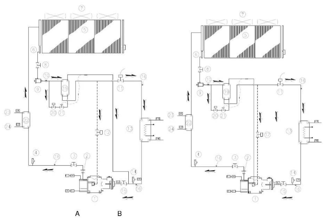
D-EIMAC00208-16EU - 8/192
| English | Deutsch | Français | Nederlands | Español | |
| 1. | Compressor | Verdichter | Compresseur | Compressor | Compresor |
| 2. | Non-return valve | Rückschiagventil | Clapet de non retour | Terugslagklep | Válvula de no retorno |
| 3. | Discharge shutoff valve | Vorlaufabsparventil | Robinet de refoulement | Persafsluter | Grifo de salida |
| 4. | High-pressure safety valve | Hochdruck-Sicherheitsventil | Soupape de sécurité haute pression | Veiligheidsklep hoge druk | Válvula de seguridad de alta presión |
| 5. | Condenser coli | Verflüssigerregister | Batterie à condensation | Condensorgroep | Bateriaí condensadora |
| 6. | Built-in undercooling section | Eingebaute Unterkühlungssektion | Section de sous-refroidissement intégrée | Geïntegreerde onderkoelingsectie | Sección de subentriamiento integrada |
| 7. | Axial ventilator | Axialventilator | Ventilateur axial | Axiale ventilator | Ventilador axial |
| 8. | Liquid line isolating tap | Absperrhahn der Flüssigkeitsleitung | Robinet d'isolement de la ligne du liquide | Afsluiter van de vloeistoflijn | Grifo de corte de la línea del líquido |
| 9. | Dehydration filter | Entwässerungstifter | Filtre déshydrateur | Dehydratatielfilter | Filtro deshidratador |
| 10. | Liquid and humidity indicator | Flüssigkeits- und Feuchtigkeitsanzeige | Indicateur de liquide et humidité | Vloeistof- en vochtigheidsindicator | Indicador de líquido y humedad |
| 11. | Electronic expansion valve | Elektronisches Expansionsventil | Détendeur électronique | Elektronisch expansieventiel | Válvula de expansión electrónica |
| 12. | Liquid injection solenoid valve | Solenodventil zur Flüssigkelsoinspritzung | Vanne soléncide pour injection du liquide | Magneetklep voor vloeistofinjectie | Válvula solenoide para inyección de líquido |
| 13. | Direct expansion evaporator | Direktexpansionsverdampfer | Evaporateur à détente directe | Verdamper met rechtstreekse expansie | Evaporador de expansión directa |
| 14. | Low pressure safety valve | Niederdruck Sicherheitsventil | Soupape de sécurité à basse pression | Veiligheidsklep lage druk | Válvula de seguridad de baja presión |
| 15. | Suction shutoff valve | Absporventil Saugleitung | Robinet d'aspiration | Aanzuiging afsluitklep | Grifo de aspiración |
| 16. | Service port | Wartungsklappe | Port de maintenance | Dienstuijke | Portillo para asistencia |
| 17. | Water outlet connection | Anschluss Wasserauslauf | Connexion sortie eau | Aansluiting uitgang water | Conexión de la salida de agua |
| 18. | Water inlet connection | Anschluss Wassorzulauf | Connexion entrée eau | Aansluiting ingang water | Conexión de la entrada de agua |
| 19. | Additional Subcooler (or economiser) | Zusätzlich Unterkühler (oder Economiser) | Sous-refroidisseur (ou économiseur) supplémentaire | Extra onderkoeler (of economiser) | Subenriador (o economizador) adicional |
| 20. | Additional Subcooler (or economiser) solenoid valve | Solenodventil für zusätzlichen Unterkühler (oder Economiser) | Vanne soléncide du sous-refroidisseur (ou économiseur) supplémentaire | Magneetklep extra onderkoeler (of economiser) | Válvula solenoide subenriador (o economizador) adicional |
| 21. | Additional subcooler (or economiser) thermostatic expansion valve | Thermostatisches Expansionsventil für zusätzlichen Unterkühler (oder Economiser) | Detendeur thermostatique du sous-refroidisseur (ou économiseur) supplémentaire | Thermostatisch expansieventiel extra onderkoeler (of economiser) | Válvula de expansion termostática subenriador (o economizador) adicional |
| 22. | Heat recovery exchanger | Wärmetauscher für Rückgewinnung | Echangeur de récupération de chaleur | Warmtewisselaar warmterecuperatie | Intercambiador del recuperador de calor |
| 23. | Heat recovery water inlet | Wasserzulauf Wärmerückgewinnung | Entrée eau de récupération de chaleur | Watertoevoer warmterecuperatie | Entrada de agua del recuperador de calor |
| 24. | Heat recovery water outlet | Wasserauslauf Wärmerückgewinnung | Sortie eau de récupération de chaleur | Wateruitaat warmterecuperatie | Salida de agua del recuperador de calor |
| ST1 | Suction temperature probe | Ansaugtemperaturfühler | Sonde de température aspiration | Temperatuursonde aanzuiging | Sonda de temperatura en aspiración |
| WL1 | Low pressure transducer | Niederdrucksensor | Transducteur basse pression | Omzetter lage druk | Transductor de baja presión |
| WO1. | Oil pressure transducer | Oldrucksensor | Transducteur pression de l'huile | Omzetter oliedruk | Transductor de presión del aceite |
| WH1. | High-pressure transducer | Hochdrucksensor | Transducteur haute pression | Omzetter hoge druk | Transductor de alta presión |
| WD1. | Discharge temperature sensor Oil | Öl/Auslassstemperaturfühler | Huile/capleur température de vidange | Olie/sensor uillaattemperatuur | Aceite/sensor de temperatura de descarga |
| F13. | High-pressure pressure switch | Maximum-Druckwächter | Pressostal haute pression | Drukregelaar hoge druk | Presostato de alta presión |
| WIE. | Water entering temperature probe | Temperaturfühler Wasserzulauf | Sonde de température entrée eau | Temperatuursonde watertoevoer | Sonda de temperatura de entrada del agua |
| WOE. | Water leaving temperature probe | Temperaturfühler Wasserauslauf | Sonde de température sortie eau | Temperatuursonde waterruitaat | Sonda de temperatura de salida del agua |
| WIR. | Heat recovery water entering temperature probe | Temperaturfühler Wasserzulauf Wärmerückgewinnung | Sonde de température de l'entrée d'eau de récupération de chaleur | Temperatuursonde watertoevoer warmterecuperatie | Sonda de temperatura de entrada de agua del recuperador de calor |
| WOR. | Heat recovery water leaving temperature probe | Temperaturfühler Wasserauslauf Wärmerückgewinnung | Sonde de température de la sortie d'eau de récupération de chaleur | Temperatuursonde waterruitaat warmterecuperatie | Sonda de temperatura de salida de agua del recuperador de calor |
D-EIMAC00208-16EU - 9/192
| Italiano | Ελληνικά | Português | Русский | Swedish | Norsk | Finnish | |
| 1. | Compressoros | Συμπεστής | Compressor | Kompressor | Kompressor | Kompressor | Kompressor |
| 2. | Valvola di non ritorno | Βαλβίβα ελγχου | Válvula de não retorno | Обратный клапан | Backventil | Tilbakeslgeventil | Tekaiskluventilli |
| 3. | Rubinetto di mandata | Στρόφγγα ροης | Tomira do mandaca | Отсенной клапан на навнетании | Tryksvatlängningavontil | Avstongningavontil på utlop | Potaton tyljönnysvontilli |
| 4. | Valvola di sicurezza alla pressione | Βαλβίβα οφφαλειος υρωλές πίεσης | Válvula de segurança de alla prosaão | Преоцен적인 клапан по высокому давлению | Högtryoks säkorhotavontil | Sikkorhotavontil for høytyk | Korkeapsino turvavontilli |
| 5. | Bateria concensante | Μποτορία συμτεκωνηση | Bateria concensante | Konденсатор | Kondensor | Kondensatorbatter | Jäähdytyksierukka |
| 6. | Sezione di soltoffredimentamento integrata | Ενσυμπαστινο τυμα υτόψυτης | Soção do subarrotoomonto integrada | Встренная сения перекомпленения | Incygpo undorkytingsssection | Innobygot undertorkingsssection | Intogrotu alljahdytyksjon osa |
| 7. | Ventilatore assisiæ | Αναριστρος οξονα | Ventilador axial | Освей bentialaptor | Axialliffik | Axialventilátor | Akiaaliputhalin |
| 8. | Rubinetto di isocamento della linea del liquido | Στρόφγα πρόνεσης της γορομής υγρού | Toméira de solamento da linha do liquido | Отсенной клапан пénévaliche inlinii | Isoleringlock välskeledning | Avstengningslugg på flynde linjo | Nestelijan sulkuhana |
| 9. | Filtro distratatore | Φίλρο αρήρενος | Filtro desirador | фильтр асуштений | Avaškurspfiller | Avvluringsfaller | Kulwussuodalin |
| 10. | Indicatore di liquido e unidita | Δείκης υρού και υγροσιος | Indicador de liquido e humidade | Индикатор アхкности | Vålske och fulkivsare | Vøeske og fulkighels seglas | Neste ja kostausmillari |
| 11. | Valvola di espansione electronica | Βαλβίβα τρέκορενος επικκούης | Válvula de expansão eletrónica | Электронный расшиентальный клапан | Elektronisk expansionaventil | Elektronisk ekspansjonsventil | Elektroninen pasunlaventilli |
| 12. | Valvola solencide per iniezione di liquido | Συληνεωσης βαξίδα για την εγχουτη υγρού | Válvula solenóide para inyeção de liquido | Соленонный клапан вприсивания жидости | Magnetventil för välskeinjycering | Magnetventil för væskeinjekasjon | Solenodiventilli nesteruskutakszen |
| 13. | Evaporator a espansione directa | Αχεη επίκτοση εζατριση | Evaporador do opansae direta | Испаритель прямого расширения | Förängare direkte kyling | Direkte ekspansorscavaporator | Suorapaisunta høyystin |
| 14. | Valvola di sicurozza a bassa pressione | Βαλβίβα οφφαλειος χωμηής πίεσης | Válvula do sogurança a baixa pressão | Valvola di sicurozza a bassa pressione | Lågtrycks säkorhotavontil | Sikkorhotavontil for lavtykk | Matalacaino turvavontilli |
| 15. | Rubinetto di ascorizone | Βρέση ονορρόφησης | Toméira de aspiração | Rubinetto de aspirazione | Sugavstngningssventil | Avstongningavontil på innlop | Imuhana |
| 16. | Portfolio cor assistenza | Πόρτα βοθέσος | Porta para assistência | Portfolio por assistência | Serviclucka | Serviclucko | Hooliolukku |
| 17. | Connosistno uscita acqua | Σύνέση εξόδου νερου | Conexão para salda os água | Concessione vesota acqua | Anslutring vettonutopp | Forbindolsc for vanutop | Vodon ulostulolitos |
| 18. | Connosistno ingrosso acqua | Σύνέση εξόδου νερου | Conexão para entrada de água | Concessione ingresso acqua | Anslutring vettoninlopp | Forbindolsc for vanwinlisp | Vodon sääänmonolitios |
| 19. | Sottotrafoodactor (o economizzatore) aggiuntivo | Επεραδεση subcoder (i) economiciser) | Subarrocoodor (ou economicizador) adicional | Дополнительный переконадитель (или экономійдер) | Extra underkylare (eller kyling) | Tillogsunorkpeler (olor fodovannstorvarmer) | Yilmääränon allijahöytin (tai säääzyksikkö) |
| 20. | Valvola soionido soltoffredistore (o economizzatore) aggiuntivo | Επεραδεση subcoder (i) economiciser) | Válvula solenóide subarrefecedor (ou economicizador) adicional | Соленонный клапан дополнительного переконадителя (или экономійдер) | Magnetventil för extra underkylare (eller kyling) | Magnetventil för illeggsunderkjeler (eller fodovannstorvarmer) | Yilmääränon allijahöytlinon (la säääzyksikkö) sovanoldiventilli |
| 21. | Valvola di espansione termodistica soltoffredistore (o economizzatore) aggiuntivo | Επεραδεση δαλβίβα θερομοτοκής επίτεσισης subcoder (i) economiciser) | Válvula de expansão termodistica subarrefecedor (ou economicizador) adicional | Термостатический клапан дополнительного переконадителя (или экономійдер) | Temmostalsk expansionsventil för extra underkylare (eller kyling) | Temmostalsk ekspansjonsventil for illeggsunderkjeler (eller fodovannstorvarmer) | Yilmääränen allijahöytlinen (la säääzyksikkö) ternostaattinen pasunlaventilli |
| 22. | Scambiatone recupero di calore | Μετατοπίος ονόκτησης θερώτησης | Permutador de recuperação de calor | Тепловбименник рекуператор | Äterwinningsvärmeväxlare | Veksler for varmegjenwinning | Lämmbövhaldin lämmörsilcontotolla |
| 23. | Ingresso acqua recupero di calore | Εξοδος νερου ονόκτησης θερώτησης | Entrodo da agua de recuperação de calor | Вход воды в рекуператор телна | Vatteninloop återwinningsvärme | Varmegjenwinning i vanminlop | Veden sisäämneno lämmörsilteenotto |
| 24. | Uscita acqua recupero di calore | Εξοδος νερου ονόκτησης θερώτησης | Saïda da agua de recuperação de calor | Выход воды на рекуператора телна | Vatteninloop återwinningsvärme | Varmegjenwinning i vanminlop | Veden ulcsulo lämmörsilconotto |
| ST1 | Sonda temperatura aspirazione | Λοθήμες υναρεδιρης θερροκρασίας | Sonda da temperatura de aspiração | Датчик температуры на всасывания | Sond sugtemooratur | Temporaturfolor i innlep | Imun lampöbla-anturi |
| WL1 | Trasutorto bassa pressione | Μετατοπίος χωμηής πίεσης | Transductor da baikas pressão | Датчик máximo давления | Lågtrycksomvendiare | Lavtrykksomtonfer | Matalapainanturi |
| WO1. | Trasutorto pressione olio | Μετατοπίος πίεσης αλδου | Transductor de pressão do óleo | Датчик давления места | Oljetrycksomvendiare | Oljetryckomtonfer | Oljetypsineantud |
| WH1. | Trasutorto alta pressione | Μετατοπίος υγμής πίεσης | Transductor da alta pressão | Датчик высокого давления | Hogtycksomvandiro | Hegtykksomtonfer | Korkecapsinanturi |
| WD1. | Olo-sonsono temperatura di ecoico | Λαθλασεητρα εξόδου δεροκρασίας | Olo-losensor temperatura de descarga | Датчик температуры масла на кнатнганики | Utsląspatemporatursensor/ Olja | Utsląspatemporatur sensoriolje | Potolatämpdólian ólysurturi |
| F13. | Pressostato alla pressione | Σαστηρο ρερμος υγμής πίεσης | Pressostato alta pressão | Реле высокого давления | Högtrykksmälare | Hogtrykkspressostat | Korkeapsine kyłkon |
| WIE. | Sonda temperatura ingresso acqua | Ασθητρας θερμοκρασίας απόδου νερού | Sonda de temperatura da entrada da agua | Датчик температуры воды на входе | Temperaturson Inlopcsvatten | Temporaturfolor for venn I imgang | Vodin sisäämnemon lämpöltia-enturi |
| WOE. | Sonda temperatura uscita acqua | Ασθητρας θερμοκρασίας εξόδου νερού | Sonda de temperatura da salida da agua | Датчик температуры воды на выходе | Temperaturson Utoppsavten | Temperaturfoler for vann i utpang | Uloclulevan veden lämpöltia-enturi |
| WIR. | Sonda temperatura ingresso acqua recupero di calore | Ασθητρας θερμοκρασίας ονόκτησης θερωμήτης επόδου νερού | Sonda de temperatura da entrada da agua de recuperação de calor | Датчик температуры на входе воды в рекуператора телна | Temperaturson för inlopp stervinningsvärmevatten | Temperaturfaler for varmagienwinning i vanminlop | Veden sisäämnemon lämpöltia-enturi lämmörsilconotto |
| WOR. | Sonda temperatura uscita acqua recupero di calore | Ασθητρας θερμοκρασίας ονόκτησης θερωμήτης εξόδου νερού | Sonda de temperatura da salida da agua de recuperação de calor | Датчик температуры на выходе воды из рекуператора телна | Temperaturson för inlopp stervinningsvärmevatten | Temperaturfaler for varmagienwinning i vanminlop | Veden ulcsulo lämpöltia-enturi lämmörsilconotto |
D-EIMAC00208-16EU - 10/192
| Polyskk | Čech | Hrvat | Magyar | Român | Slovenski | Български | Slovenský | |
| 1. | Sprzarka | Kompressor | Kompressor | Kompressor | Kompressor | Kompressor | Kompressor | Kompressor |
| 2. | Zawor zwotny | Zobny venil | Venil za sprječavanje vraćai | Visszaosapó szolop | Valvá unidirecională | Nopravnii ventil | Задържац клапан | Spitiny vontil |
| 3. | Zawor floczny | Vytačný kohutek | Ulszna slavina | Batolyo ezláró casp | Robnet evacuare | Odvotni ventil | Kran за подаване | Vytačny kohutik |
| 4. | Zawor bezleczeristwa wysokého cílnena | Bepečnostni ventil vysokého tlaku | Sgumosni ventil visok priliszi | Biztonsági szolop nagy nyomá | Valvá de siguraná ħinalta presi | Visokotlačni varnostni ventil | Предзален клапан викою напагане | Bepečnostny ventil vysok tlaku |
| 5. | Woznowna srapiacza | Kondenzni batete | Kondonzioska batorija | Kondonzálo ogyság | Batorte do condonsaro | Kondorzacijsko navito | Kondenziracha baterja | Konderzana bažtins |
| 6. | Wuzownma sekja dochadzania | Integrovana člasi podinložavočno zařízeni | Sekoja za podrashladivanje | Beepteti tulhitó egység | Secljune de subracire integrati | Vgrajeni podhlatjeni del | Modyu za svaloxohtavdane vgraden | Ingrenovač našef podhizovaceho zarlade |
| 7. | Wentylator oslowy | Axialni ventilator | Axialni ventilator | Tengelyirany ventilator | Ventilator axial | Axialni ventilator | Вентиатори за извекдане | Axialny ventilator |
| 8. | Zawor odinajcy iinię plyn | Izolačni kohutek linie kapeli | Slavina za izolačju linje sa tekučinom | Foyadék izoláó casp | Robnet izolare linie lichid | Izolačjeki ventilă za tekočinsko lii | Изолирац, klapan linnia na техност | Izolačny kohutik linie kvaç |
| 9. | Fitr odvsniacza | Fitr dehydratoru | Fillar za odstranjivanje vlage | Vizlidenitiš služro | Filtru deshidrator | Sušaliri filter | Dekudiuraç finipur | Filler dehydratora |
| 10. | Wskažnik plynu i wigoci | Ukazatel kapaliny s vlikcasi | Pokravilač tekučine i vlasnos | Folyadék és nedvesag mutali | Indicator de lichid și umiditate | Indikator tekočine in vlage | Индиватор за техност и влажност | Ukazovatel kvapalliny a vlikcasi |
| 11. | Elektroniczny zawor rozprę | Expanzi elektronicky ventil | Ventil elektronics ekspanzycje | Elektromos szablyozdoszlep | Valvá de expansione electroni | Elektronski ekspanzijeki ventil | Klapan за электронно разширенне | Expanzy elektronický veni |
| 12. | Zawor elektronmagnetychny wirsikwianya plynu | Solenodni ventil pro vsifikov kapaliny | Ventil solendot za ubrizgovar tekučine | Foyadék befesckondežo szole zselep | Valvá solenoidă pentru inojcția lichidului | Elektronmagnetni ventilă za vblzg tekočine | Klapan зарекдане за инжектиране техност | Solenodni ventil pre vstrekovanje kvapalliny |
| 13. | Parownik z bezpośrednim rozprzęvenem | Evaporator s pärincu expanz | Ispanvač se direktron ekspanzljom | Közvellen szrabelyozásu párol | Vaporizator cu expansiune din | Izpranlik z direktno ekspanzijo | Изопатор с директно изолиране | Evaporator s priamou expanzou |
| 14. | Zawor bezleczeristwa niški cílnena | Bepečnostni ventil nizkého | Sgumosni ventil pod niskim prislakem | Biztonsági szolop alacsony ny | Valvá de siguraná joassă presi | Nizkołačni varnostni ventil | Предзален клапан за нико налжан | Bepečnostny ventil nizke tlaku |
| 15. | Zawor sswarny | Nasavač kohoutok | Slavina za uiss | Elszivó zarócasp | Robnet de aspirate | Sosanii vortil | Kran за засмукване | Nasavač konutik |
| 16. | Drzywizci sorwisowo | Servisni ovlika | Vratásca za servisiranje | Szoritz ajto | Usă pentru asistență | Sorsina vrata | Ословязаєв люк | Sorvisno dvorka |
| 17. | Podłączenie odpolywu wody | Zapojoni vystup vody | Priklučsk izlaz vode | Vizleareszilo cealtakozás | Conexune legins apă | Prikluček za odvod vode | Bržska inhod voda | Zapojonic vystup vody |
| 18. | Podłączenie dopolywu wody | Zapojoni vystup vody | Priklučsk izlaz vode | Viz bononet oseltikožas | Conexune intrare apă | Prikluček za odvod vode | Bržska вход voda | Zapojonic vystup vody |
| 19. | Dodatkowy dochladzacz (lu ekonomizera) | Podrchizovaci zařizemi(aneb plidatný ekonomizator) | Podrashladivačili dodalni ekonomizator) | Kiegészliu tulhitó (vagy economiser) | Subracitor (sau economizor) suplimentar | Dodatna cnota za podhlejevanje grenik) | Сарыконачител (или топлообмення доплінителен | Podrchizovace zariđeni alebo pridivanje ekonomiz |
| 20. | Elektronmagnetychny zawor dodatkowego dochladzacz (lub ekonomizera) | Solonodni ventil podrhizav zařizumi(anebo phistadneho ekonomizator) | Ventil solendot podrashladiva dodalni ekonomizator) | Kogészliu tulhitó (vagy economiser) szolenoid szelepe | Valvá solenoida subracitor (sa economicor) suplimentar | Magnetoternični ventil dodatna za podlhlejevanje (si gretnika) | Klapan зарекдане сарыконачителі топлообмення) доплінителен | Solonodni vortili podrhizovacech zariđene (alebo pridivanje ekonomiz) |
| 21. | Termosaltyczny zawor rozprzęwny dodatkowego dochladzacza (lub ekonomizera) | Tepelný expanzi ventil podonlazovacino zařizini (si plidatneho ekonomizatoru) | Ventil za termosiatsku ekopa podrashladivačili dodatnog ekonomizators) | Kiegészliu tulhitó (vagy economiser) hászabalyozó sze | Valvá solenoida de expansiun termostatic subracitor (sau economicor) suplimentar | Termoslateki ekspanzijski ventil dodatne enode za podhlajevanje grenika) | Klapan термостатично рахшенине SARыкиначител (или топлообмення доплінителен | Tepelný expanzi ventil podrhizovacech zariđene (alebo pridivanje ekonomiz) |
| 22. | Wymiennik odzyskiwanego ciepla | Vyměnik rekuperace lepla | Izmjenjivač nadoknadivanje topline | Höviszanyerč húcserelő | Schimbátor recuperare căldurč | Izmjerjevalnik za rekuperacijo lo | Топлообменник топлинина енергия | Vymennik rekuperácie lep |
| 23. | Doplyw vody odzyskiwanego ciepla | Vstup vody rekuperace lepla | Ulasz vode nadoknadivanje to | Höviszanyerč viz bemenet | Intrare apă recuperare căldurč | Vhod vode za rekuperacijo toplc | Вход вода юлинина енергия | Vstup vody rekuperácie le |
| 24. | Odplyw vody odzyskiwanego ciepla | Vystup vody rekuperace lepli | Izlaz vode nadoknadivanje to | Höviszanyerč viz kimenet | Evacuare apă recuperare căldi | Izhod vode za rekuperacijo toplc | Izhod vode топлинина енергия | Vystup vody rekuperácia i |
| ST1 | Sonda temperatury zasysa | Tepelná sonda nadavšni | Temperatura sonda uslisa | Elsvišvási hómérsekletmérő szc | Sondi di temperaturá aspirali | Sonda temperatury v sosalnom toxokogu | Temperaturna condua za засмукване | Tepelná sonda nasvania |
| W1.1 | Przetvomik nizkigo cílnica | Transkulator nizkého tlaku | Transkulator nizkého prílsak | Kis nyomás transzkuktor | Trasuctor preslune joasă | Nizkolčni preptomik | Конавтор носке напагане | Transkulator nizkého tlaku |
| W0.1 | Przetvomik ositelisa oleju | Transkulator tlaku ovje | Transkulator prílsak ulja | Clajyromás transzkuktor | Trasuctor preslune ulei | Przetvomik oljnega tlaka | Конавтор напагане на маслото | Transkidor tlaku oleja |
| WD.1 | Przetvomik wysokéko ośr | Transkulator wysokého tlaku | Transkductor visok prílsak | Nagy nyomás transzkuktor | Trasuctor ineta preslune | Visokotlačni preptomik | Конавтор високо напагане | Transkidor wysokého tler |
| O1.1 | Olejcszunk temperatury odprowadzania | Olejcsznor teploty na odvod | Ulješensor temperature odvo | Clay kimenet nómérseklet erz | Ulei' senzor temperaturve o odvo | Olješensor temperature v odvo | Маслосенсор: температура на отвекдане | Olejcsznor tapioty na odv |
| F13. | Prescelat wysokéko cílnie | Prescelat wysokého tlaku | Mjerac prílska visokí prílsak | Nagy nyomás nyomáskapock | Preslost at inala' preslune | Visokolčni preslostat | Контактор ограничител високо нали | Presosta vyszckého tlaku |
| WIE. | Sonda temperatury dopływ wody | Topolná sonda vestup vody | Temporatura sonda ulaza v | Bemeneti vizhámérseklet mérő szorda | Sonda temperaturá apă intrare | Sonda temperatury vhodne voda | Temperaturna condua входa | Topolná sonda vestup vody |
| WOE. | Sonda temperatury odpływ wody | Tepelna sonda vestup vody | Temporatura sonda ulaza v | Kimeneti vizhámérseklet mérő szorda | Sonda temperaturá apă leșire | Sonda temperatury izhdne voda | Temperaturna condua ihxod voda | Tepelna sonda vestup vody |
| WIR. | Sonda temperatury dopływ wody odzyskiwanego ciepla | Tepelna sonda vestup vody Rekuparose tepla | Temporatura sonda ulaza v nadoknadivanje topline | Höviszanyerč viz bemeneti hómérsekletmérő szonda | Sonda temperaturá intrare apă recuperare căldurč | Sonda temperatury vhodne voda rekuparasejlo toplote | Temperaturna condua входa troplina energria | Tepelna sonda vestup vody Rekuparasei tepla |
| WOR. | Sonda temperatury odpływ wody odzyskiwanego ciepla | Tepelna sonda vestup vody Rekuparase lepla | Temporatura sonda ulaza v nadoknadivanje topline | Höviszanyerč viz kimeneti hómérsekletmérő szonda | Sonda temperaturá sejre apă recuperare căldurč | Sonda temperatury izhdne voda rekuparasejlo toplote | Temperaturna condua ihxod voda troplina energria | Tepelna sonda vystup voda Rekuparasei tepla |
D-EIMAC00208-16EU - 11/192
ENGLISH - ORIGINAL INSTRUCTIONS
This manual is an important supporting document for qualified personnel but it is not intended to replace such personnel.
Thank you for purchasing this chiller

READ THIS MANUAL CAREFULLY BEFORE INSTALLING AND STARTING UP THE UNIT. IMPROPER INSTALLATION COULD RESULT IN ELECTRIC SHOCK, SHORT-CIRCUIT, LEAKS, FIRE OR OTHER DAMAGE TO THE EQUIPMENT OR INJURE TO PEOPLE. THE UNIT MUST BE INSTALLED BY A PROFESSIONAL OPERATOR/TECHNICIAN UNIT STARTUP HAS TO BE PERFORMED BY AUTHORIZED AND TRAINED PROFESSIONAL ALL ACTIVITIES HAVE TO BE PERFORMED ACCORDING TO LOCAL LAWS AND REGULATION. UNIT INSTALLATION AND START UP IS ABOSOLUTELY FORBIDDEN IF ALL INSTRUCTION CONTAINED IN THIS MANUAL ARE NOT CLEAR. IF CASE OF DOUBT CONTACT THE MANUFACTURER REPRESENTATIVE FOR ADVICE AND INFORMATION.
Description
The unit you bought is an "air cooled chiller", a machine aimed to cool water (or water-glycol mixture) within the limits described in the following. The unit operation is based on vapour compression, condensation and evaporation according to reverse Carnot cycle. The main components are:
- Screw compressor to rise the refrigerant vapour pressure from evaporation pressure to condensation pressure
- Evaporator, where the low pressure liquid refrigerant evaporates so cooling the water
- Condenser, where high pressure vapour condensate rejecting heat removed from the chilled water in the atmosphere thanks to an air cooled heat exchanger.
- Expansion valve allowing to reduced the pressure of condensed liquid from coinsensation pressure to evaporation pressure
General Information

All units are delivered with wiring diagrams, certified drawings, nameplate; and DOC (Declaration Of Conformity); these documents show all technical data for the unit you have bought and they MUST BE
CONSIDERED ESSENTIAL DOCUMENTS OF THIS MANUAL
In case of any discrepancy between this manual and the equipment's documents please refer to on board documents. In case of any doubt contact the manufacturer representative..
The purpose of this manual is to allow the installer and the qualified operator to ensure proper installation, commissioning and maintenance of the unit, without any risk to people, animals and/or objects.
Receiving the unit
The unit must be inspected for any possible damage immediately upon reaching final place of installation. All components described in the delivery note must be inspected and checked.
Should the unit be damaged, do not remove the damaged material and immediately report the damage to the transportation company and request they inspect the unit..
Immediately report the damage to the manufacturer representative, a set of photographs are helpful in recognizing responsibility
Damage must not be repaired before the inspection of the transportation company representative.
Before installing the unit, check that the model and power supply voltage shown on the nameplate are correct.
Responsibility for any damage after acceptance of the unit cannot be attributed to the manufacturer.
Operating limits
Storing
Environmental conditions must be within the following limits:
Minimum ambient temperature : -20°C Maximum ambient temperature : 57°C
Maximum R.H. : 95% not condensing
Storing below the minimum temperature may cause damage to components. Storing above the maximum temperature causes opening of safety valves. Storing in condensing atmosphere may damage electronic components.
Operation
Operation out of the mentioned limits may damage the unit. In case of doubts contact manufacturer representative.
Figure 1 - Description of the labels applied to the electrical panel
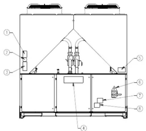
text_image
Technical schematic diagram of an industrial or mechanical system with numbered components and piping connections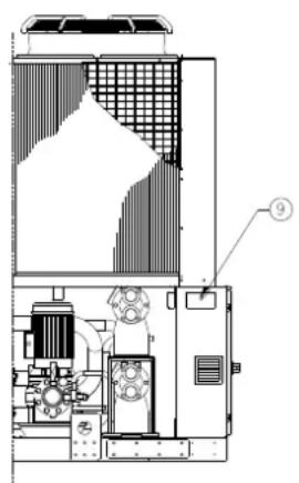
text_image
Technical diagram of an industrial machine with labeled components and a numbered annotation pointing to part 9.Label Identification
| 1 – Non flammable gas symbol | 6 – Electrical hazard symbol |
| 2 – Gas type | 7 – Hazardous Voltage warning |
| 3 – Unit nameplate data | 8 – Cable tightening warning |
| 4 – Manufacturer's logo | 9 – Lifting instructions |
| 5 – Water circuit filling warning |
Figure 2 - Operating limits
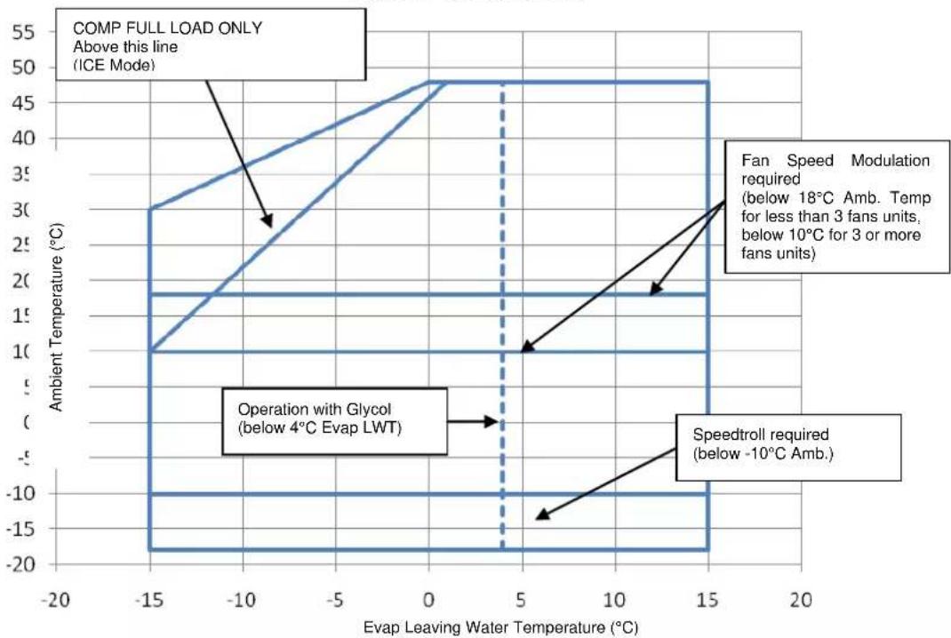
line
| Evap Leaving Water Temperature (°C) | Ambient Temperature (°C) | | ----------------------------------- | ------------------------ | | -15 | 3 | | 0 | 50 | | 15 | 50 | | 5 | 10 | | 15 | -15 |Safety
The unit must be firmly secured to the soil. It is essential to observe the following instructions:
- The unit can only be lifted using the lifting points marked in yellow fixed to its base.
- It is forbidden to access the electrical components without having opened the unit main switch and switched off the power supply.
- It is forbidden to access the electrical components without using an insulating platform. Do not access the electrical components if water and/or moisture are present.
- Sharp edges and the surface of the condenser section could cause injury. Avoid direct contact and use adequate protection device
- Switch off power supply, by opening the main switch, before servicing the cooling fans and/or compressors. Failure to observe this rule could result in serious personal injury.
- Do not introduce solid objects into the water pipes while the unit is connected to the system.
- A mechanical filter must be installed on the water pipe connected to the heat exchanger inlet.
- The unit is supplied with safety valves, that are installed both on the high-pressure and on the low-pressure sides of the refrigerant circuit.
It is absolutely forbidden to remove all protections of moving parts.
In case of sudden stop of the unit, follow the instructions on the Control Panel Operating Manual which is part of the onboard documentation delivered to the end user.
It is strongly recommended to perform installation and maintenance with other people. In case of accidental injury or unease, it is necessary to:
- keep calm
- press the alarm button if present in the installation site
- move the injured person in a warm place far from the unit and in rest position
- contact immediately emergency rescue personnel of the building or the Health Emergency Service
- wait without leaving the injured person alone until the rescue operators come
- give all necessary information to the rescue operators

Avoid installing the chiller in areas that could be dangerous during maintenance operations, such as platforms without parapets or railings or areas not complying with the clearance requirements around the chiller.
Noise
The unit is a source of noise mainly due to rotation of compressors and fans.
The noise level for each model size is listed in sales documentation.
If the unit is correctly installed, operated and manteined the noise emission level do not require any special protection device to operate continuously close to the unit without any risk. In case of installation with special noise requirements it could be necessary to install additional sound attenuation devices.
Moving and lifting
Avoid bumping and/or jolting during loading/unloading unit from the truck and moving it. Do not push or pull the unit from any part other than the base frame. Secure the unit inside the truck to prevent it from moving and causing damages. Do not allow any part of the unit to fall during transportation or loading/unloading.
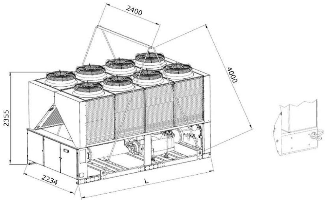
All units of the are supplied with lifting points marked in yellow. Only these points may be used for lifting the unit, as shown in the following Figure 3.

Both the lifting ropes and the spacing bars must be strong enough to support the unit safely. Please check the unit's weight on the unit nameplate.
The unit must be lifted with the utmost attention and care following lifting label instructions; lift unit very slowly, keeping it perfectly level..
Positioning and assembly
All units are designed for installation outdoors, either on balconies or on the ground, provided that the installation area is free of obstacles that could reduce air flow to the condensers coil.
The unit must be installed on a robust and perfectly level foundation; should the unit be installed on balconies or roofs, it
might be necessary to use weight distribution beams.
Figure 3 - Lifting the unit
text_image
2400 4000 2355 2234 LFor installation on the ground, a strong concrete base, at least 250 mm thickness and wider than the unit must be provided.
This base must be able to support the weight of the unit. If the uni is installed in places that are easily accessible to people and animals, it is advisable to install protection grids for the condenser and compressor sections.
To ensure best performance on the installation site, the following precautions and instructions must be followed:
- Avoid air flow recirculation.
- Make sure that there are no obstacles to hamper air flow.
- Make sure to provide a strong and solid foundation to reduce noise and vibrations.
- Avoid installation in particularly dusty environments, in order to reduce soiling of condensers coils.
- The water in the system must be particularly clean and all traces of oil and rust must be removed. A mechanical water filter must be installed on the unit's inlet piping.
Minimum space requirements
It is fundamental to respect minimum distances on all units in order to ensure optimum ventilation to the condenser coils. When deciding where to position the unit and to ensure a proper air flow, the following factors must be taken into consideration:
- avoid any warm air recirculation
- avoid insufficient air supply to the air-cooled condenser.
Both these conditions can cause an increase of condensing pressure, which leads to a reduction in energy efficiency and refrigerating capacity.
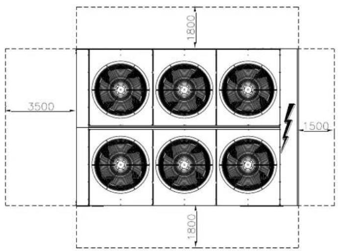
Any side of the unit must be accessible for post-installation maintenance operations. Figure 3 shows the minimum space required.
Vertical air discharge must not be obstructed.
If the unit is surrounded by walls or obstacles of the same height as the unit, this must be installed at a distance no lower than 2500 mm. If these obstacles are higher, the unit must be installed at a distance no lower than 3000 mm.
Should the unit be installed without observing the recommended minimum distances from walls and/or vertical obstacles, there could be a combination of warm air recirculation and/or insufficient supply to the air-cooled condenser which could cause a reduction of capacity and efficiency.
In any case, the microprocessor will allow the unit to adapt itself to new operating conditions and deliver the maximum available capacity under any given circumstances, even if the lateral distance is lower than recommended, unless the operating conditions should affect personnel safety or unit reliability.
When two or more units are positioned side by side, a distance of at least 3600 mm between condenser banks is recommended.
For further solutions, please consult manufacturer representative.
Sound protection
When sound levels require special control, great care must be exercised to isolate the unit from its base by appropriately applying anti-vibration elements (supplied as an option). Flexible joints must be installed on the water connections, as well.
Water piping
Piping must be designed with the lowest number of elbows and the lowest number of vertical changes of direction. In this way, installation costs are reduced considerably and system performance is improved.
The water system must have:
- Anti-vibration mountings in order to reduce transmission of vibrations to the structures.
- Isolating valves to isolate the unit from the water system during service.
- Manual or automatic air venting device at the system's highest point.; drain device at the system's lowest point.
-
Neither the evaporator nor the heat recovery device must be positioned at the system's highest point.
-
A suitable device that can maintain the water system under pressure (expansion tank, etc.).
-
Water temperature and pressure indicators to assist the operator during service and maintenance.
Figure 4 - Minimum clearance requirements
text_image
1800 3500 1500 1800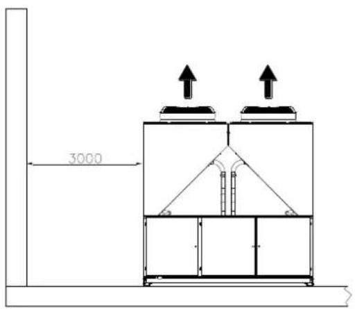
text_image
3000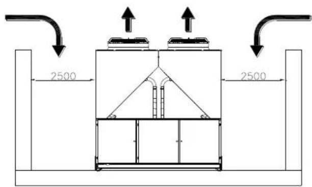
text_image
2500 2500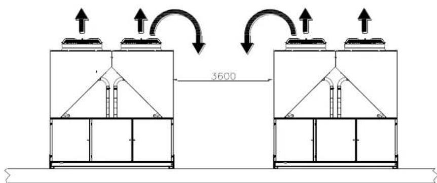
text_image
3600- A filter or device that can remove particles from the fluid. The use of a filter extends the life of the evaporator and pump and helps to keep the water system in a better condition.
- Evaporator has an electrical resistance with a thermostat that ensures protection against water freezing at ambient temperatures as low as -25^ . All the other water
piping/devices outside the unit must therefore be protected against freezing.
-
The heat recovery device must be emptied of water during the winter season, unless an ethylene glycol mixture in appropriate percentage is added to the water circuit.
-
If case of unit substitution, the entire water system must be emptied and cleaned before the new unit is installed. Regular tests and proper chemical treatment of water are recommended before starting up the new unit.
-
In the event that glycol is added to the water system as anti-freeze protection, pay attention to the fact that suction pressure will be lower, the unit's performance will be lower and water pressure drops will be greater. All unit-protection
systems, such as anti-freeze, and low-pressure protection will need to be readjusted. 12. Before insulating water piping, check that there are no leaks.
Figure 5 - Water piping connection for evaporator
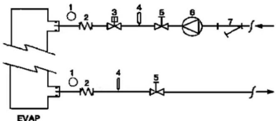
flowchart
graph TD
    A["Component 1"] --> B["Component 2"]
    B --> C["Component 3"]
    C --> D["Component 4"]
    D --> E["Component 5"]
    E --> F["Component 6"]
    F --> G["Component 7"]
    G --> H["Output f"]
    I["Component 1"] --> J["Component 2"]
    J --> K["Component 3"]
    K --> L["Component 4"]
    L --> M["Component 5"]
    M --> N["Component 6"]
    N --> O["Output f"]
-
Pressure Gauge
-
Flexible connector
-
Flow switch
-
Temperature probe
-
Isolation Valve
-
Pump
-
Filter
Figure 6 - Water piping connection for heat recovery exchangers
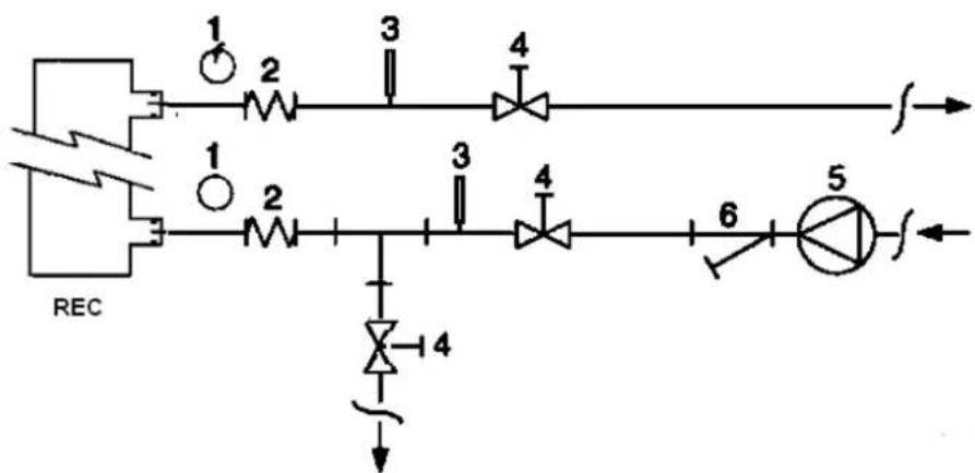
flowchart
graph TD
    REC --> 1
    REC --> 2
    1 --> 2
    2 --> 3
    3 --> 4
    4 --> f
    REC --> 1
    REC --> 2
    2 --> 3
    3 --> 4
    4 --> 6
    6 --> f'
    4 --> 5
    5 --> f
    4 --> 4
    4 --> 3
    3 --> 4
    4 --> 3
    3 --> 2
    2 --> 1
-
Pressure Gauge
-
Flexible connector
-
Temperature probe
-
Isolation Valve
-
Pump
-
Filter
Water treatment
Before putting the unit into operation, clean the water circuit. Dirt, scales, corrosion debris and other other material can accumulate inside the heat exchanger and reduce its heat exchanging capacity. Pressure drop can increase as well, thus reducing water flow. Proper water treatment therefore reduces
the risk of corrosion, erosion, scaling, etc. The most appropriate water treatment must be determined locally, according to the type of system and water characteristics. The manufacturer is not responsible for damage to or malfunctioning of equipment caused by failure to treat water or by improperly treated water.
Table 1 - Acceptable water quality limits
| pH (25°C) | 6,8:8,0 | Total Hardness (mg CaCO_3 /l) | < 200 | |
| Electrical conductivity μS/cm (25°C) | <800 | Iron (mg Fe / l) | < 1.0 | |
| Chloride ion (mg Cl^- /l) | <200 | Sulphide ion (mg S^2- /l) | None | |
| Sulphate ion (mg SO_4^2- /l) | <200 | Ammonium ion (mg NH_4^+ /l) | < 1.0 | |
| Alkalinity (mg CaCO_3 /l) | <100 | Silica (mg SiO_2 /l) | < 50 |
Evaporator and recovery exchangers anti-freeze protection
All evaporators are supplied with a thermostatically controlled anti-freeze electrical resistance, which provides adequate anti-freeze protection at temperatures as low as -25^ . However, unless the heat exchangers are completely empty and cleaned with anti-freeze solution, additional methods should also be used against freezing.
Two or more of below protection methods should be considered when designing the system as a whole:
Continuous water flow circulation inside piping and exchangers
– Addition of an appropriate amount of glycol inside the water circuit
– Additional heat insulation and heating of exposed piping
– Emptying and cleaning of the heat exchanger during the winter season
It is the responsibility of the installer and/or of local maintenance personnel to ensure that described anti-freeze methods are used. Make sure that appropriate anti-freeze protection is maintained at all times. Failing to follow the instructions above could result in unit damage. Damage caused by freezing is not covered by the warranty.
Installing the flow switch
To ensure sufficient water flow through the evaporator, it is essential that a flow switch be installed on the water circuit. The flow switch can be installed either on the inlet or outlet water piping. The purpose of the flow switch is to stop the unit in the event of interrupted water flow, thus protecting the evaporator from freezing.
The manufacturer offers, as optional, a flow switch that has been selected for this purpose.
This paddle-type flow switch is suitable for heavy-duty outdoor applications (IP67) and pipe diameters in the range of 1" to 6". The flow switch is provided with a clean contact which must be electrically connected to terminals shown in the wiring diagram.
Flow switch has to be tune to intervene when the evaporator water flow is lower than 50% of nomila flow rate.
Heat recovery
Units may be optionally equipped with heat recovery system. This system in made by a water cooled heat exchanger located on the compressors discharge pipe and a dedicated management of condensing pressure.
To guarantee compressor operation within its envelope, units with heat recovery cannot operate with water temperature of the heat recovery water lower than 28^ C.
It is a responsibility of plant designer and chiller installer to grantee the respect of this value (e.g. using recirculating bypass valve)
Electrical Installation
General specifications

All electrical connections to the unit must be carried out in compliance with laws and regulations in force.
All installation, management and maintenance activities must be carried out by qualified personnel. Refer to the specific wiring diagram for the unit you have bought. Should the wiring diagram not be on the unit or should it have been lost, please contact your manufacturer representative, who will send you a copy. In case of discrepancy between wiring diagram and electrical panel/cables please contact the manufacturer representative.
Only use copper conductors. Failure to use copper conductors could result in overheating or corrosion at connection points and could damage the unit.
To avoid interference, all control wires must be connected separately from the power cables. Use different electrical passage ducts for this purpose.
Before servicing the unit in any way, open the general disconnecting switch on the unit's main power supply.
When the unit is off but the disconnecting switch is in the closed position, unused circuits are live, as well.
Never open the terminal board box of the compressors before having opened the unit's general disconnecting switch.
Contemporaneity of single-phase and three-phase loads and unbalance between phases could cause leakages towards ground up to 150mA, during the normal operation of the units of the series.
If the unit includes devices that cause superior harmonics (like VFD and phase cut), the leakage towards ground could increase to very higher values (about 2 Ampere).
The protections for the power supply system have to be designed according to the above mentioned values.
Operation
Operator's responsibilities
It is essential that the operator is appropriately trained and becomes familiar with the system before operating the unit. In addition to reading this manual, the operator must study the microprocessor operating manual and the wiring diagram in order to understand start-up sequence, operation, shutdown sequence and operation of all the safety devices.
During the unit's initial start-up phase, a technician authorized by the manufacturer is available to answer any questions and to give instructions as to the correct operating procedures.
The operator must keep a record of operating data for every installed unit. Another record should also be kept of all the periodical maintenance and servicing activities.
If the operator notes abnormal or unusual operating conditions, he is advised to consult the technical service authorized by the manufacturer.
Routine maintenance
Minimum maintenance activities are listed in
Table 2
Service and limited warranty
All units are factory-tested and guaranteed for 12 months as of the first start-up or 18 months as of delivery.
These units have been developed and constructed according to high quality standards ensuring years of failure-free operation. It is important, however, to ensure proper and periodical maintenance in accordance with all the procedures listed in this manual and with good practice of machines maintenance.
We strongly advise stipulating a maintenance contract with a service authorized by the manufacturer in order to ensure efficient and problem-free service, thanks to the expertise and experience of our personnel.
It must also be taken into consideration that the unit requires maintenance also during the warranty period.
It must be borne in mind that operating the unit in an inappropriate manner, beyond its operating limits or not performing proper maintenance according to this manual can void the warranty.
Observe the following points in particular, in order to conform to warranty limits:
- The unit cannot function beyond the specified limits
-
The electrical power supply must be within the voltage limits and without voltage harmonics or sudden changes.
-
The three-phase power supply must not have un balance between phases exceeding 3%. The unit must stay turned off until the electrical problem has been solved.
-
No safety device, either mechanical, electrical or electronic must be disabled or overridden.
-
The water used for filling the water circuit must be clean and suitably treated. A mechanical filter must be installed at the point closest to the evaporator inlet.
-
Unless there is a specific agreement at the time of ordering, the evaporator water flow rate must never be above 120% and below 80% of the nominal flow rate.
Periodic obligatory checks and starting up of appliances under pressure
The units are included in category IV of the classification established by the European Directive PED 2014/68/EU.
For chillers belonging to this category, some local regulations require a periodic inspection by an authorized agency. Please check with your local requirements.
Table 2 - Routine maintenance programme
| List of Activities | Weekly | Monthly (Note 1) | Yearly/Seasonal (Note 2) |
| General: | |||
| Reading of operating data (Note 3) | X | ||
| Visual inspection of unit for any damage and/or loosening | X | ||
| Verification of thermal insulation integrity | X | ||
| Clean and paint where necessary | X | ||
| Analysis of water (6) | X | ||
| Check of flow switch operation | X | ||
| Electrical: | |||
| Verification of control sequence | X | ||
| Verify contactor wear – Replace if necessary | X | ||
| Verify that all electrical terminals are tight – Tighten if necessary | X | ||
| Clean inside the electrical control board | X | ||
| Visual inspection of components for any signs of overheating | X | ||
| Verify operation of compressor and electrical resistance | X | ||
| Measure compressor motor insulation using the Megger | X | ||
| Refrigeration circuit: | |||
| Check for any refrigerant leakage | X | ||
| Verify refrigerant flow using the liquid sight glass – Sight glass full | X | ||
| Verify filter dryer pressure drop | X | ||
| Verify oil filter pressure drop (Note 5) | X | ||
| Analyse compressor vibrations | X | ||
| Analyse compressor oil acidity (7) | X | ||
| Condenser section: | |||
| Clean condenser banks (Note 4) | X | ||
| Verify that fans are well tightened | X | ||
| Verify condenser bank fins – Comb if necessary | X |
Notes:
1. Monthly activities include all the weekly ones.
2. The annual (or early season) activities include all weekly and monthly activities.
3. Unit operating values should be read on a daily basis thus keeping high observation standards.
4. In environments with a high concentration of air-borne particles, it might be necessary to clean the condenser bank more often.
5. Replace the oil filter when the pressure drop across it reaches 2.0 bar.
6. Check for any dissolved metals.
7. TAN (Total Acid Number) : ≤0,10 : No action
Between 0.10 and 0.19 : Replace anti-acid filters and re-check after 1000 running hours. Continue to replace filters until the TAN is lower than 0.10.
0,19 : Replace oil, oil filter and filter dryer. Verify at regular intervals.
Important information regarding the refrigerant used
This product contains fluorinated greenhouse gases. Do not vent gases into the atmosphere.
Refrigerant type: R134a
GWP(1) value: 1430
(1)GWP = Global Warming Potential
The refrigerant quantity necessary for standard operation is indicated on the unit name plate.
Real refrigerant quantity charged in the unit is listed on a silver sticker inside the electrical panel.
Periodical inspections for refrigerant leaks may be required depending on European or local legislation.
Please contact your local dealer for more information.
Factory and Field charged units instructions
(Important information regarding the refrigerant used)
The refrigerant system will be charged with fluorinated greenhouse gases.
Do not vent gases into the atmosphere.
1 Fill in with indelible ink the refrigerant charge label supplied with the product as following instructions:
- the refrigerant charge for each circuit (1; 2; 3)
- the total refrigerant charge (1 + 2 + 3)
- calculate the greenhouse gas emission with the following formula:
GWP value of the refrigerant x Total refrigerant charge (in kg) / 1000
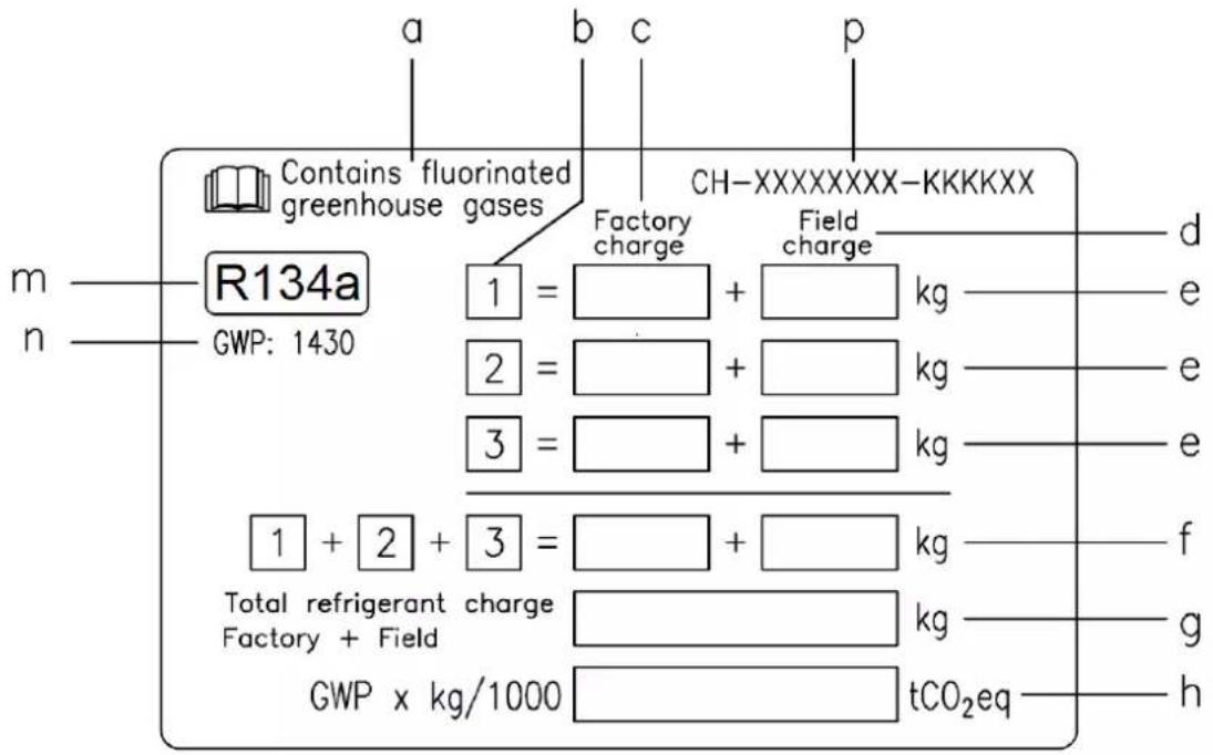
text_image
a b c p Contains fluorinated greenhouse gases CH-XXXXXXXXKKKKXX Factory charge Field charge R134a GWP: 1430 1 = ______+ ______+ kg 2 = ______+ ______+ kg 3 = ______+ ______+ kg 1 + 2 + 3 = ______+ ______+ kg Total refrigerant charge Factory + Field kg GWP x kg/1000 _________ tCO₂eq m n d e e e f g ha Contains fluorinated greenhouse gases
b Circuit number
c Factory charge
d Field charge
e Refrigerant charge for each circuit (according to the number of circuits)
f Total refrigerant charge
g Total refrigerant charge (Factory + Field)
h Greenhouse gas emission of the total refrigerant charge expressed as tonnes of CO2 equivalent
m Refrigerant type
n GWP = Global Warming Potential
p Unit serial number
2 The filled out label must be adhered inside the electrical panel.
Periodical inspections for refrigerant leaks may be required depending on European or local legislation. Please contact your local dealer for more information.
NOTICE
In Europe, the greenhouse gas emission of the total refrigerant charge in the system
(expressed as tonnes CO_2 equivalent) is used to determine the maintenance intervals.
Follow the applicable legislation.
Formula to calculate the greenhouse gas emission:
GWP value of the refrigerant x Total refrigerant charge (in kg) / 1000
Use the GWP value mentioned on the greenhouse gases label. This GWP value is
based on the 4th IPCC Assessment Report. The GWP value mentioned in the manual might be outdated (i.e. based on the 3rd IPCC Assessment Report)
Disposal
The unit is made of metal, plastic and electronic parts. All these parts must be disposed of in accordance with the local regulations in terms of disposal.
Lead batteries must be collected and sent to specific refuse collection centres.
Oil must be collected and sent to specific refuse collection centres.
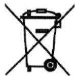
This manual is a technical aid and does not represent a binding offer. The content cannot be held as explicitly or implicitly guaranteed as complete, precise or reliable. All data and specifications contained herein may be modified without notice. The data communicated at the moment of the order shall hold firm.
The manufacturer shall assume no liability whatsoever for any direct or indirect damage, in the widest sense of the term, ensuing from or connected with the use and/or interpretation of this manual.
We reserve the right to make changes in design and construction at any time without notice, thus the cover picture is not binding.
text_image
Technical diagram of an industrial or mechanical system with numbered components, likely a control or processing unit.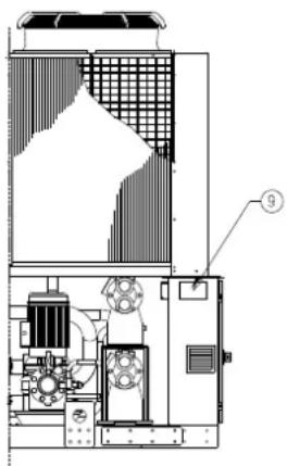
text_image
Technical diagram of an industrial machine with labeled component ⑨text_image
a b c p Contains fluorinated greenhouse gases CH-XXXXXXXXX-KKKKXX m n R134a GWP: 1430 Factory charge Field charge 1 = ______+ + ______+ kg 2 = ______+ + ______+ kg 3 = ______+ + ______+ kg 1 + 2 + 3 = ______+ + ______+ kg Total refrigerant charge Factory + Field kg GWP x kg/1000 _________ tCO₂eq d e e e f g hn GWP = Global warming potential (Treibhauspotential)
text_image
Technical schematic diagram of an industrial or mechanical system with numbered components and piping connections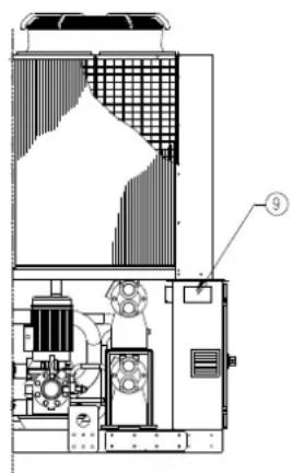
text_image
Technical schematic diagram of an industrial machine with labeled component 9Figure 4 – Espaces techniques minimum
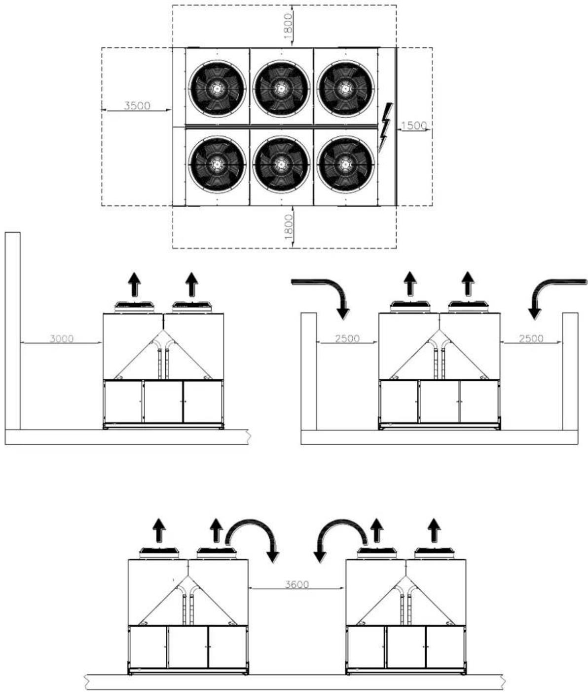
text_image
1800 3500 1500 1800 3000 2500 2500 3600text_image
a b c p Contains fluorinated greenhouse gases CH-XXXXXXXXX-KKKKXX m n R134a GWP: 1430 Factory charge Field charge 1 = ______+ _________ kg 2 = ______+ _________ kg 3 = ______+ _________ kg 1 + 2 + 3 = ______+ _________ kg Total refrigerant charge Factory + Field kg GWP x kg/1000 _________ tCO₂eq d e e e f g htext_image
Technical schematic diagram of an industrial equipment or processing unit with numbered components labeled 1 through 8.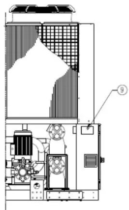
text_image
Technical schematic diagram of an industrial machine with labeled component 9text_image
a b c p Contains fluorinated greenhouse gases CH-XXXXXXXXKKKKXX Factory charge Field charge R134a GWP: 1430 1 = ______+ ______+ kg 2 = ______+ ______+ kg 3 = ______+ ______+ kg 1 + 2 + 3 = ______+ ______+ kg Total refrigerant charge Factory + Field kg GWP x kg/1000 tCO₂eq d e e e f g htext_image
Technical schematic diagram of an industrial equipment or processing unit with numbered components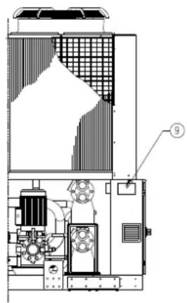
text_image
Technical schematic diagram of an industrial machine with labeled component 9text_image
a b c p Contains fluorinated greenhouse gases CH-XXXXXXXXX-KKKKXX m n R134a GWP: 1430 Factory charge Field charge 1 = ______+ + ______+ kg 2 = ______+ + ______+ kg 3 = ______+ + ______+ kg 1 + 2 + 3 = ______+ + ______+ kg Total refrigerant charge Factory + Field kg GWP x kg/1000 tCO₂eq d e e e f g htext_image
Technical schematic diagram of an industrial equipment or processing unit with numbered components and piping connections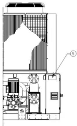
text_image
Technical schematic diagram of a mechanical device with labeled component 9text_image
a b c p Contains fluorinated greenhouse gases CH-XXXXXXXXX-KKKKXX m n R134a GWP: 1430 Factory charge Field charge 1 = ______+ + ______+ kg 2 = ______+ + ______+ kg 3 = ______+ + ______+ kg 1 + 2 + 3 = ______+ + ______+ kg Total refrigerant charge Factory + Field kg GWP x kg/1000 tCO₂eq d e e e f g htext_image
Technical schematic diagram of an industrial equipment or processing unit with numbered components and piping connectionstext_image
Technical diagram of an industrial machine with labeled component 9text_image
a b c p Contains fluorinated greenhouse gases CH-XXXXXXXXX-KKKKXX m n R134a GWP: 1430 Factory charge Field charge 1 = ______+ _________ kg 2 = ______+ _________ kg 3 = ______+ _________ kg 1 + 2 + 3 = ______+ _________ kg Total refrigerant charge Factory + Field kg GWP x kg/1000 _________ tCO₂eq d e e e f g htext_image
Technical schematic diagram of an industrial or mechanical system with numbered components and piping connections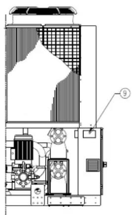
text_image
Technical schematic diagram of an industrial machine with labeled component 9text_image
a b c p Contains fluorinated greenhouse gases CH-XXXXXXXXX-KKKKXX m n R134a GWP: 1430 Factory charge Field charge 1 = ______+ + ______+ kg 2 = ______+ + ______+ kg 3 = ______+ + ______+ kg 1 + 2 + 3 = ______+ + ______+ kg Total refrigerant charge Factory + Field kg GWP x kg/1000 tCO₂eq d e e e f g htext_image
Technical schematic diagram of an industrial or mechanical system with numbered components and piping connections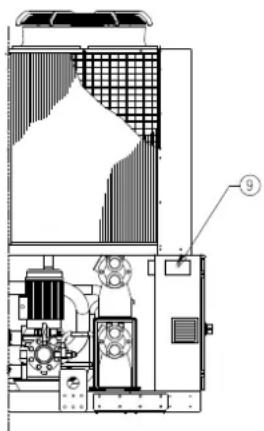
text_image
Technical schematic diagram of an industrial machine with labeled component ⑨text_image
a b c p Contains fluorinated greenhouse gases CH-XXXXXXXXX-KKKKXX m n R134a GWP: 1430 Factory charge Field charge 1 = ______+ + ______+ kg 2 = ______+ + ______+ kg 3 = ______+ + ______+ kg 1 + 2 + 3 = ______+ + ______+ kg Total refrigerant charge Factory + Field kg GWP x kg/1000 tCO₂eq d e e e f g hLÄS NOGGRANT DENNA MANUAL INNAN
INSTALLATION OCH IBRUKTAGANDE AV ENHETEN PÅBÖRJAS.
EN FELAKTIG INSTALLATION KAN ORSAKA
ELCHOCKER, KORTSLUTNINGAR, LÄCKAGE, BRAND ELLER ANDRA SKADOR PÅ APPARATEN ELLER PÅ PERSONER.
ENHETEN SKA INSTALLERAS AV EN PROFESSIONELL OPERATÖR/TEKNIKER.
ENHETENS IBRUKTAGNING SKA UTFÖRAS AV
AUKTORISERADE OCH FÖRBEREDDA
YRKESPERSONER.
ALLA AKTIVITETER SKA UTFÖRAS MED HÄNSYN TILL
GÄLLANDE LOKALA LAGAR OCH NORMATIV.
INSTALLATION OCH START AV ENHETEN ÄR
ABSOLUT FÖRBJUDNA OM INTE ALLA
INSTRUKTIONERNA I DENNA MANUAL ÄR TYDLIGA.
VID TVIVEL, KONTAKTA TILLVERKARENS
REPRESENTANT FÖR INFORMATION OCH RÅD.
Beskrivning
text_image
Technical schematic diagram of an industrial or mechanical system with numbered components and piping connections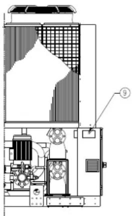
text_image
Technical schematic diagram of an industrial machine with labeled component ⑨text_image
a b c p Contains fluorinated greenhouse gases CH-XXXXXXXXX-KKKKXX m n R134a GWP: 1430 Factory charge Field charge 1 = ______+ + ______+ kg 2 = ______+ + ______+ kg 3 = ______+ + ______+ kg 1 + 2 + 3 = ______+ + ______+ kg Total refrigerant charge Factory + Field kg GWP x kg/1000 _________ tCO₂eq d e e e f g htext_image
Technical schematic diagram of an industrial or mechanical system with numbered components and piping connections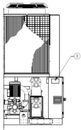
text_image
Technical schematic diagram of a mechanical or electrical device with labeled component 9text_image
a b c p Contains fluorinated greenhouse gases CH-XXXXXXXXKKKKXX Factory charge Field charge R134a GWP: 1430 1 = □ + □ kg 2 = □ + □ kg 3 = □ + □ kg 1 + 2 + 3 = □ + □ kg Total refrigerant charge Factory + Field kg GWP x kg/1000 tCO₂eq m n d e e e f g ha Inneholder fluorholdige klimagasser
b Kretsnummer
c Fabrikkfylt
d Feltfylt
text_image
Technical schematic diagram of an industrial or mechanical system with numbered components and piping connections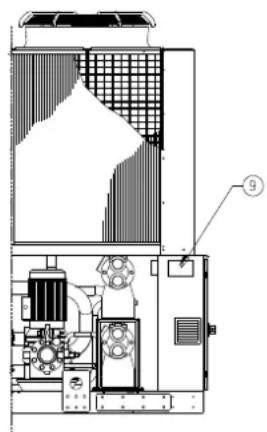
text_image
Technical schematic diagram of an industrial machine with labeled component 9Tarran tunnistus
text_image
a b c p Contains fluorinated greenhouse gases CH-XXXXXXXXKKKKXX Factory charge Field charge R134a 1 = ______+ ______+ kg 2 = ______+ ______+ kg 3 = ______+ ______+ kg 1 + 2 + 3 = ______+ ______+ kg Total refrigerant charge Factory + Field GWP x kg/1000 _________kg tCO₂eq m n GWP: 1430 d e e e f g htext_image
Technical schematic diagram of an industrial or mechanical system with numbered components and piping connections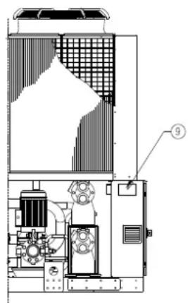
text_image
Technical schematic diagram of an industrial machine with labeled component 9text_image
a b c p Contains fluorinated greenhouse gases CH-XXXXXXXXX-KKKKXX Factory charge Field charge R134a GWP: 1430 1 = ______+ + ______+ kg 2 = ______+ + ______+ kg 3 = ______+ + ______+ kg 1 + 2 + 3 = ______+ + ______+ kg Total refrigerant charge Factory + Field GWP x kg/1000 _________kg tCO₂eq m n d e e e f g htext_image
Technical schematic diagram of an industrial or mechanical system with numbered components and piping connections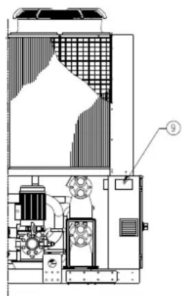
text_image
Technical schematic diagram of a mechanical or electrical device with labeled component 9Identifikace štítku
text_image
a b c p Contains fluorinated greenhouse gases CH-XXXXXXXXKKKKXX Factory charge Field charge R134a GWP: 1430 1 = ______+ ______+ kg 2 = ______+ ______+ kg 3 = ______+ ______+ kg 1 + 2 + 3 = ______+ ______+ kg Total refrigerant charge Factory + Field kg GWP x kg/1000 _________ tCO₂eq m n d e e e f g htext_image
Technical schematic diagram of an industrial or mechanical system with numbered components and piping connections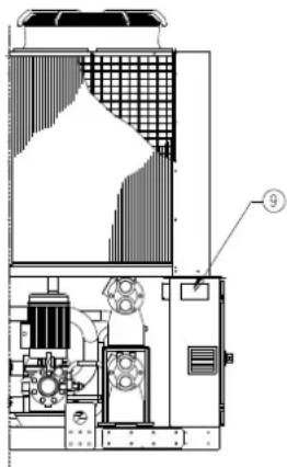
text_image
Technical schematic diagram of an industrial machine with labeled component ⑨Identifikacija etikete
| 1 – Simbol za nezapaljivi plin | 6 – Simbol o električnoj opasnosti |
| 2 – Vrsta plina | 7 – Upozorenje o opasnom naponu |
| 3 – Podaci identifikacione ploče cjeline | 8 – Upozorenje o stezanju kabela |
| 4 – Proizvođačeva oznaka | 9 – Upute u svezi sa podizanjem |
| 5 – Upozorenje o tome da je krug napunjen vodom |
Slika 2 – Operativna ograničenja
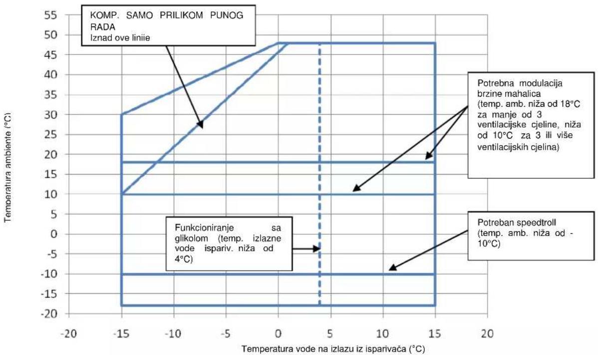
line
| Temperature vode na izlazu iz isparivača (°C) | KOMP. SAMO PRILIKOM PUNOG RADA Iznad ove linii | Funkcioniranje sa glikolom (temp. izlazne vode ispariv. niža od 4°C) | Potrebna modulacija brzine mahalica (temp. amb. niža od 18°C za manje od 3 ventilacijske cjeline, niža od 10°C za 3 ili više ventilacijskih cjelina) | Potreban speedtroll (temp. amb. niža od -10°C) | | ------------------------------------------- | -------------------------------------------------- | ---------------------------------------------------------- | ---------------------------------------------------------------------------------------- | ------------------------------------------ | | -15 | 30 | -18 | 18 | -18 | | -10 | 35 | -18 | 18 | -18 | | -5 | 40 | -18 | 18 | -18 | | 0 | 48 | -18 | 18 | -18 | | 5 | 48 | -18 | 18 | -18 | | 10 | 48 | -18 | 18 | -18 | | 15 | 48 | -18 | 18 | -18 |Sigurnost
Cjelina se treba dobro pričvrstiti za tlo.
text_image
a b c p Contains fluorinated greenhouse gases CH-XXXXXXXXX-KKKKXX m n R134a GWP: 1430 Factory charge Field charge 1 = ______+ _________ kg 2 = ______+ _________ kg 3 = ______+ _________ kg 1 + 2 + 3 = ______+ _________ kg Total refrigerant charge Factory + Field kg GWP x kg/1000 _________ tCO₂eq d e e e f g ha Sadrži fluorirane stakleničke plinove
b Broj kruga
c Tvorničko punjenje
d Punjenje na terenu
text_image
Technical schematic diagram of an industrial equipment or processing unit with numbered components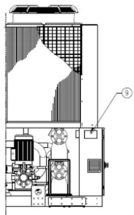
text_image
Technical schematic diagram of an industrial machine with labeled component 9A címke értelmezése
text_image
a b c p Contains fluorinated greenhouse gases CH-XXXXXXXXKKKKXX Factory charge Field charge R134a GWP: 1430 1 = □ + □ kg 2 = □ + □ kg 3 = □ + □ kg 1 + 2 + 3 = □ + □ kg Total refrigerant charge Factory + Field kg GWP x kg/1000 tCO₂eq m n d e e e f g htext_image
Technical schematic diagram of an industrial or mechanical system with numbered components and piping connections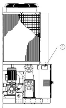
text_image
Technical schematic diagram of an industrial machine with labeled component 9text_image
a b c p Contains fluorinated greenhouse gases CH-XXXXXXXXX-KKKKXX Factory charge Field charge R134a GWP: 1430 1 = ______+ + ______+ kg 2 = ______+ + ______+ kg 3 = ______+ + ______+ kg 1 + 2 + 3 = ______+ + ______+ kg Total refrigerant charge Factory + Field GWP x kg/1000 _________kg tCO₂eq m n d e e e f g htext_image
Technical schematic diagram of an industrial or mechanical system with numbered components and piping connections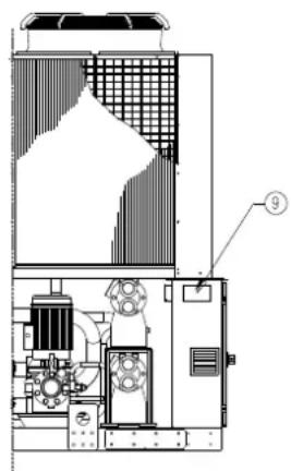
text_image
Technical schematic diagram of an industrial machine with labeled component 9Identifikacija nalepke
| 1 – Simbol nevnetljivega plina | 6 – Simbol nevarne električne napetosti |
| 2 – Vrsta plina | 7 – Nevarna napetost |
| 3 – Identifikacijska ploščica enote | 8 – Opozorilo glede privitosti vodnikov |
| 4 – Logotip proizvajalca | 9 – Navodila za dvigovanje |
| 5 – Opozorilo glede polnjenja vodnega sistema |
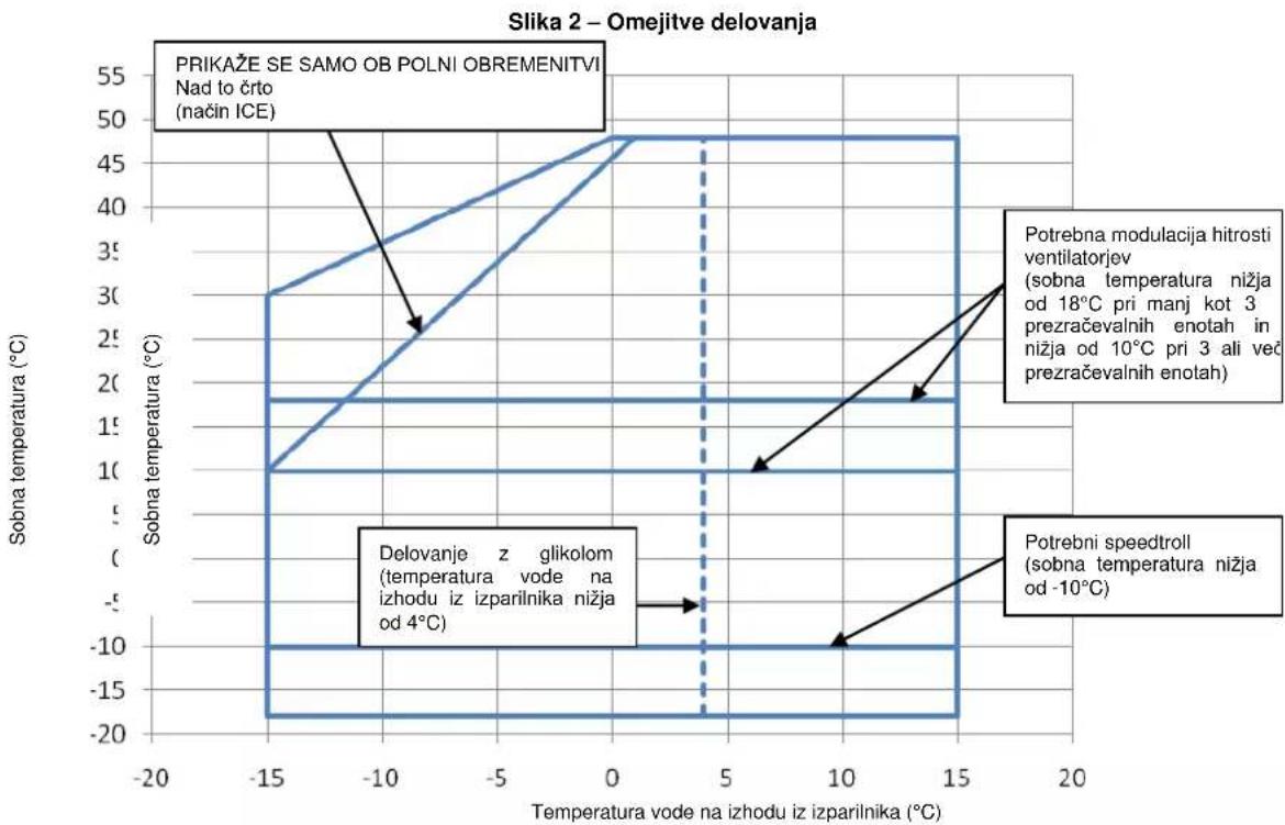
line
| Temperature vode na izhodu iz izparilnika (°C) | Sobna temperatura (°C) | | --------------------------------------------- | ---------------------- | | -15 | 3 | | -10 | 2 | | 0 | 1 | | 5 | 0 | | 10 | -1 | | 15 | -2 |Varnost
Enota mora biti čvrsto pritrjena na tla.
text_image
a b c p Contains fluorinated greenhouse gases CH-XXXXXXXXKKKKXX Factory charge Field charge R134a GWP: 1430 1 = ______+ ______+ kg 2 = ______+ ______+ kg 3 = ______+ ______+ kg 1 + 2 + 3 = ______+ ______+ kg Total refrigerant charge Factory + Field GWP x kg/1000 _________kg tCO₂eq m n d e e e f g ha Vsebuje fluorirane toplogredne pline
b Številka kroga
text_image
Technical schematic diagram of an industrial or mechanical system with numbered components and piping connections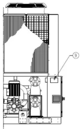
text_image
Technical schematic diagram of an industrial machine with labeled component 9text_image
a b c p Contains fluorinated greenhouse gases CH-XXXXXXXXX-KKKKXX m n R134a GWP: 1430 Factory charge Field charge 1 = ______+ + ______+ kg 2 = ______+ + ______+ kg 3 = ______+ + ______+ kg 1 + 2 + 3 = ______+ + ______+ kg Total refrigerant charge Factory + Field kg GWP x kg/1000 _________ tCO₂eq d e e e f g htext_image
Technical schematic diagram of an industrial or mechanical system with numbered components and piping connections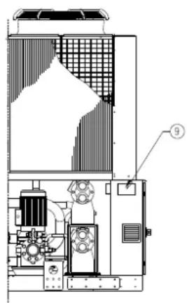
text_image
Technical schematic diagram of an industrial machine with labeled component 9text_image
a b c p Contains fluorinated greenhouse gases CH-XXXXXXXXKKKKXX Factory charge Field charge R134a GWP: 1430 1 = □ + □ kg 2 = □ + □ kg 3 = □ + □ kg 1 + 2 + 3 = □ + □ kg Total refrigerant charge Factory + Field kg GWP x kg/1000 tCO₂eq m n d e e e f g hThe present publication is drawn up by of information only and does not constitute an offer binding upon Daikin Applied Europe S.p.A.. Daikin Applied Europe S.p.A. has compiled the content of this publication to the best of its knowledge. No express or implied warranty is given for the completeness, accuracy, reliability or fitness for particular purpose of its content, and the products and services presented therein. Specification are subject to change without prior notice. Refer to the data communicated at the time of the order. Daikin Applied Europe S.p.A. explicitly rejects any liability for any direct or indirect damage, in the broadest sense, arising from or related to the use and/or interpretation of this publication. All content is copyrighted by Daikin Applied Europe S.p.A..
DAIKIN APPLIED EUROPE S.p.A.