
B451AJD-EG - Doorbells Lorex - Free user manual and instructions
Find the device manual for free B451AJD-EG Lorex in PDF.

| Product Type | Connected Video Doorbell |
| Brand | Lorex |
| Model | B451AJD-EG |
| Video Resolution | 2K QHD |
| Connectivity | Wi-Fi 2.4 GHz / 5 GHz, Bluetooth (setup) |
| Viewing Angle | Adjustable 15° horizontal, adjustable 5° vertical |
| Power Supply | 16-24 V AC (existing or supplied transformer) |
| Local Storage | Pre-installed microSD card (up to 256 GB not included) |
| Audio | Microphone and speaker, two-way communication |
| Night Vision | Yes, with mechanical IR filter |
| Motion Detection | Yes, customizable zones and adjustable sensitivity |
| Status Indicator | Multi-color LED (customizable) |
| Smart Features | Person detection, quick responses, nightlight, user sharing |
| Mobile App | Lorex Home (iOS and Android) |
| Chime Compatibility | Mechanical or electronic (chime kit included) |
| Mounting | Wall bracket with optional angle mounts (screws and anchors provided) |
| Dimensions (approx.) | 12 x 4 x 3 cm |
| Weight (approx.) | 200 g |
| Protection Class | Sheltered outdoor (do not immerse) |
| Operating Temperature | -20 °C to 50 °C |
| Package Contents | Doorbell, mounting bracket, 15° and 5° angle mounts, USB cable, chime kit, cables, mounting accessories, microSD card |
| Maintenance | Clean with a damp cloth, no abrasive products |
| Safety | Cut power before installation, respect voltage 16-24 V AC |
| Warranty | Visit lorex.com/warranty |
Frequently Asked Questions - B451AJD-EG Lorex
User questions about B451AJD-EG Lorex
0 question about this device. Answer the ones you know or ask your own.
Ask a new question about this device
Download the instructions for your Doorbells in PDF format for free! Find your manual B451AJD-EG - Lorex and take your electronic device back in hand. On this page are published all the documents necessary for the use of your device. B451AJD-EG by Lorex.
USER MANUAL B451AJD-EG Lorex
Thanks for your purchase of the 2K Video Doorbell. Here's how to get started.
Contents
Section 1 Package contents
2 Overview
3 Status indicator
4 Connect to the app
5 Preparation
6 Wiring the chime
7 Secure the mounting bracket(s)
8 Wiring the doorbell
9 Connect the doorbell
10 Lorex Home app overview
11 Troubleshooting
12 Frequently asked questions
1 Package contents
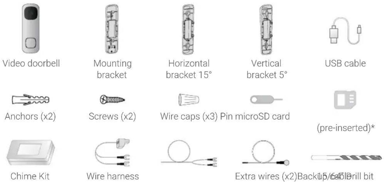
User-supplied tools
Drill
Screwdriver
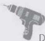
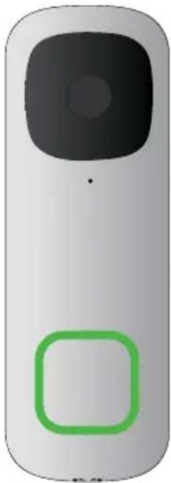
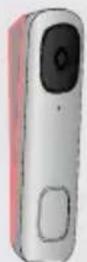
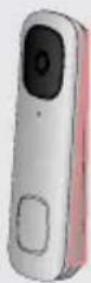
2 Overview
Front Panel Back Panel
③ Status indicator
natural_image
Front view of a gray remote control device with a black square button and a green square outline (no text or symbols)Solid blue
The video doorbell is powering on or the video doorbell is restarting.
Solid red
The video doorbell is resetting to factory default.
Solid green
The video doorbell is operating correctly.
Flashing blue slowly
The video doorbell is ready to connect.
Flashing blue rapidly
The video doorbell has detected motion.
Flashing red
The video doorbell failed to connect to the network.
Flashing green
The talking function on the video doorbell is in use.
Flashing blue, red, and green
A firmware update is in progress.
Spinning red
The video doorbell is connected to the network, but unable to access the internet.
Spinning green
The calling function on the video doorbell is in use.
4 Connect to the app
Connect to the Lorex Home app to access the doorbell's installation videos.
- If you already have the app, skip this step. Scan the QR code on the right using your mobile device's camera. Install the free Lorex Home app from the App Store™ or Google Play Store™.
- Tap the Lorex Home icon to launch the app.
- If you already have an account, skip this step. Tap Sign up, then follow the on screen prompts to create an account. Record your account details below:
Email:
Account Password:

Scan QR code for Lorex Home app
- Tap on the icon + on the top right of the screen to add a device.
- Scan the device QR code found in the box or on the back of the doorbell.

Note: If your mobile device cannot scan the QR code, tap Manually enter Device ID.
- Follow the in-app instructions to complete the installation OR refer to sections 5 through 9 in this Quick Start Guide for a written description of the installation steps.
5 Preparation
Before beginning setup, there are some essential preparations to make.
To prepare for installation:

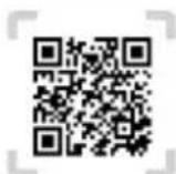
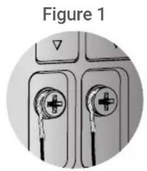
Step 1
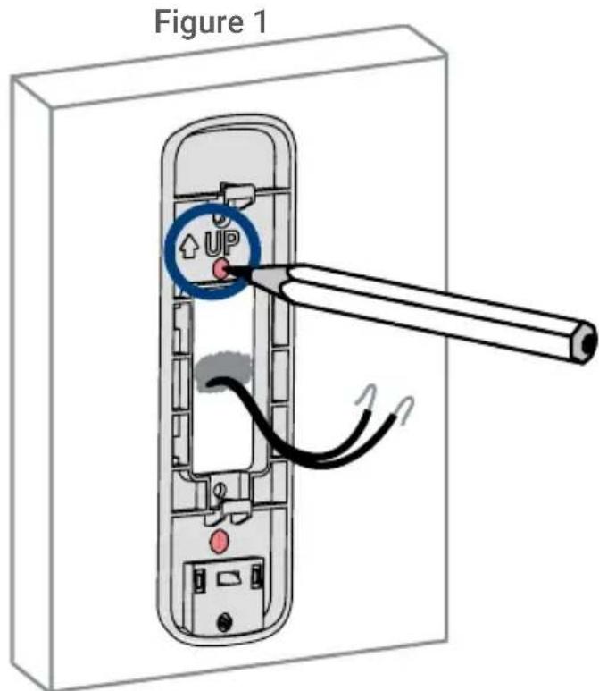
TURN OFF THE POWER RUNNING TO YOUR EXISTING DOORBELL AND CHIME BOX AT THE BREAKER (See Figure 1).
Test that power has been disconnected for both the doorbell and chime box power by pressing the doorbell. There should be no chime sound.
Always be careful when handling electrical wiring. If you're not comfortable doing it yourself, then consult a licensed electrician.
Step 2
Remove your existing doorbell and disconnect wiring (see Figure 2). Make sure to bend the power cables so they do not fall through the hole in the wall.
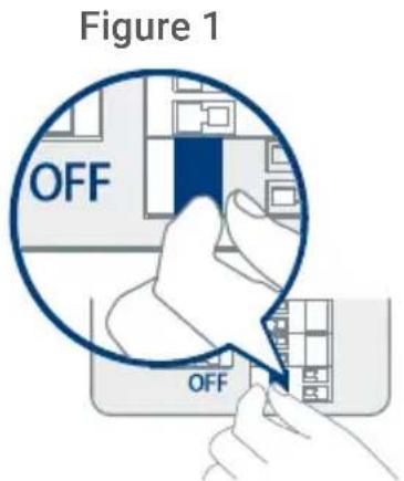
Figure 2

natural_image
Simple curved line drawing with a gray top and two black segments (no text or symbols)IMPORTANT: 16-24 VAC is required. If your house does not have this voltage, you will need a 16-24 VAC doorbell transformer or you can consult with a licensed electrician.
6 Wiring the chime
You must determine the type of doorbell chime you have in your home: electronic or mechanical. Not sure? If your doorbell chime is a classic *ding-dong* sound, chances are your chime is mechanical. If your doorbell sounds more like a melody, then your chime is electronic. If you are still not sure, remove the cover panel of your chime box - if you find springloaded levers and a physical metal chime, you have a mechanical chime.
For users with a mechanical chime, follow the extra step below to complete the installation.
For mechanical chime owners:
- Remove the cover panel of your doorbell chime box.
- Loosen the screws labeled FRONT and TRANS using a Philips head screwdriver. Do not remove the screws, and be sure to detach any connected wiring (see Figure 1).
- Connect the included chime kit to the green terminal on the end of the included wire harness (see Figure 2).
Figure 2
natural_image
Diagram of a rectangular block connected to a red wire with three terminal leads (no text or symbols)Figure 1
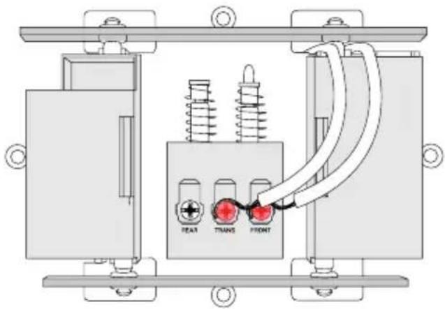
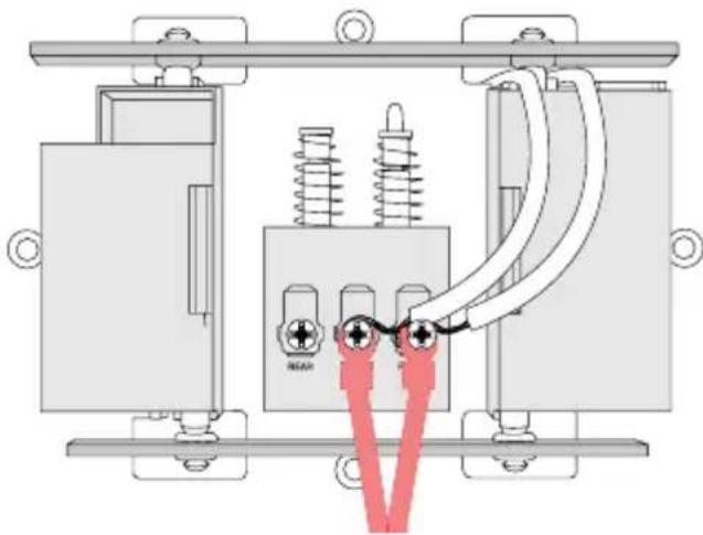
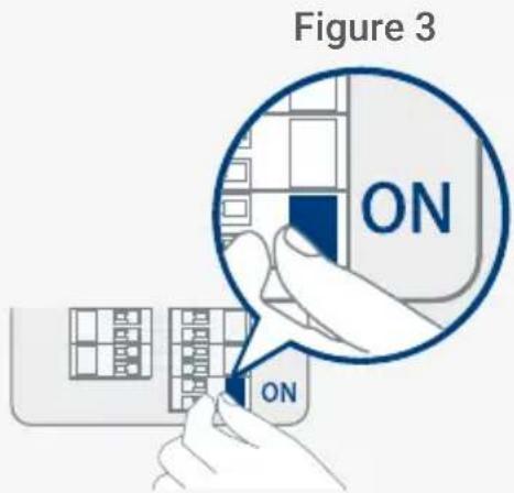
- Connect the wiring from the chime kit to the FRONT and TRANS connectors in the chime box. Ensure that the existing wiring stays connected as well (see Figure 3).

Note: You may connect either wire to either connector.
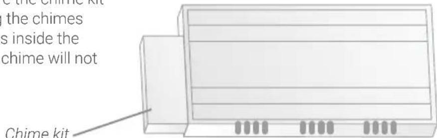
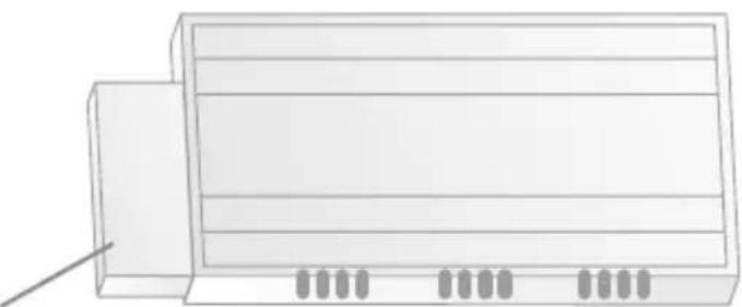
- Mount the chime kit to the inside of your chime box, or along the cover plate of the chime box, using the included double-sided tape (see Figure 4).
IMPORTANT: Use the included double-sided tape to ensure the chime kit and wires are not touching the chimes or any moving components inside the chime box, or the doorbell chime will not sound correctly.
Figure 3
natural_image
Technical diagram of an electrical circuit with springs and capacitors, no visible text or symbolsFigure 4
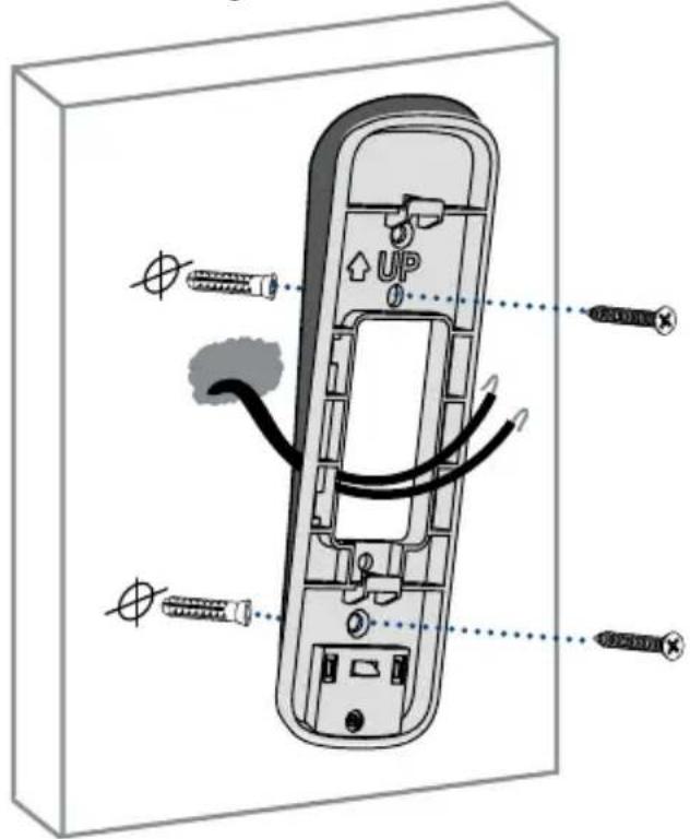
7 Secure the mounting bracket(s)
Use the mounting accessories specified below depending on the mounting location.
Step 1: Mark mounting holes
Place the mounting bracket to fit your existing doorbell wiring. Then mark the screw holes according to the mounting bracket.
IMPORTANT: Ensure that the UP arrow on the mounting bracket is always pointing up.
Step 2 (Optional): Attach an angled bracket to the mounting bracket
If you want to change the angle of the doorbell for a better view, attach one of the optional angled brackets to the mounting bracket.
- Select either the horizontal or vertical bracket according to the direction you want your doorbell to face (see Figures 2&3).
- To change the direction of the angle, simply flip the horizontal or vertical bracket upside down. Whichever direction you choose, make sure the attached mounting bracket is always facing
Option 1: Horizontal bracket
Figure 2 (bottom view)

natural_image
Close-up of a smartphone rear panel showing the 15° right angle indicator (no other text or symbols)
15° left
Option 2: Vertical bracket
Figure 3
5^ down
5^ up
-
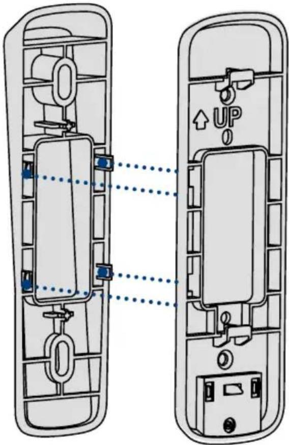
Insert the four tabs from the horizontal or vertical bracket into the the mounting bracket as shown in Figure 4. Make sure to insert in the desired direction.
-
Press the mounting bracket down. A *click* sound will indicate that the brackets are locked in.

Notes:
- You can only attach one angled bracket to the mounting bracket.
- If you would like to change the direction of the angled bracket after attaching it to the mounting bracket, gently but firmly pull them apart.
Figure 4
Step 3: Secure the mounting bracket
When installing only the mounting bracket, refer to Figure 5-a. When installing the angled bracket attached to the mounting bracket, refer to Figure 5-b.
1. For wood, drywall or soft surfaces:
Secure the mounting bracket(s) to the mounting surface using a Philips-head screwdriver and the supplied mounting screws.
2. For concrete, stucco or brick:
Use the supplied 15/64" drillbit to drill holes where marked. Use the supplied anchors and screws to secure the mounting bracket(s) to the wall.
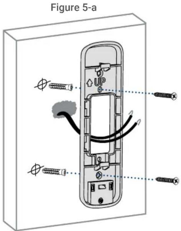

Notes:
- Ensure that the ↑upw on the mounting bracket is always pointing up.
- The (optional) angled bracket must be attached to the mounting bracket before installation.
- Ensure the power cables from the wall fit comfortably through the hole in the mounting bracket.
Figure 5-b
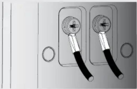
⑧ Wiring the doorbell
To wire the doorbell:
- Loosen the power port screws of the doorbell with a Philips-head screwdriver.

Note: Do not fully remove the power port screws.
- Loop the power wires underneath the power port screws (see Figure 1).
- Tighten the power port screws to secure the power wires (see Figure 2).
natural_image
Diagram of two electrical connectors with pliers, labeled Figure 1 (no text or symbols on components)Figure 2

To extend short wires (optional):
Figure 3
natural_image
Diagram of two electrical outlet switches with black and white cables, no text or symbols presentFigure 4
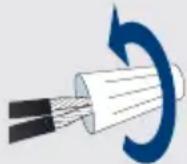
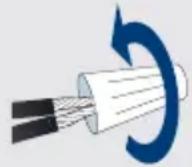
- If your existing doorbell wiring is too short, remove the power port screws completely, then thread the screws through the supplied extra wires. Use the supplied wire caps to extend your wiring (see Figure 3).
- To attach the wire cap, align the ends of your existing wiring and extra wires, place the wire cap over the exposed wiring and twist the wire nut clockwise to tighten (see Figure 4). Pull on the wires slightly to make sure that they are properly fastened inside the wire cap.
- Ensure there is enough space to fit the cable connectors and wire caps into the hole in your wall.
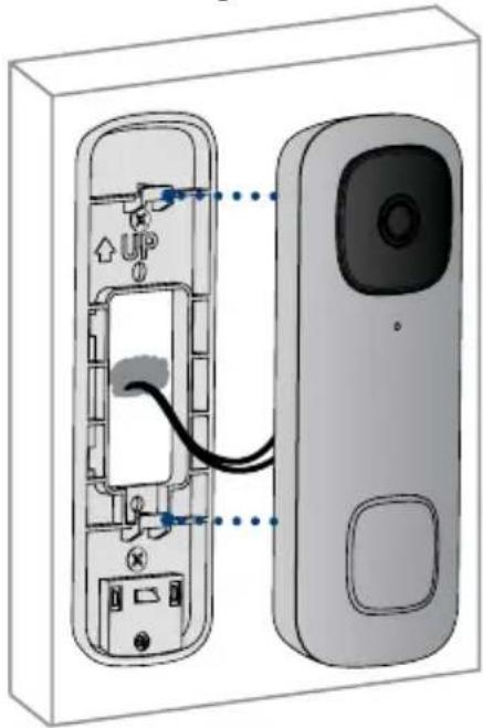
9 Connect the doorbell
To attach the doorbell to the bracket:
- Push the wiring back into the wall.
- Insert the two tabs from the mounting bracket into the doorbell (see Figure 1).
- Press the doorbell downwards. A *click* sound will indicate that it is locked in.
Figure 1
natural_image
Diagram of a device showing internal components connected to a screen, with no visible text or symbols.
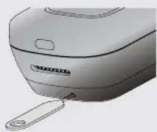
Note - If you need to remove the doorbell from the bracket:
- Insert the supplied pin into the hole at the bottom of the mounting bracket until the inner buckle is reached (see Figure 2).
- Then slide the doorbell up and remove it.
Figure 2
natural_image
Close-up of a white industrial fan or blender with a handle and label (no visible text or symbols)You may now reconnect power to the doorbell and chime at the breaker (see Figure 3).
Wait 5 minutes for the doorbell to fully power on and press the doorbell's button to ensure that the chime is operating correctly. Check section 11 for troubleshooting if needed.
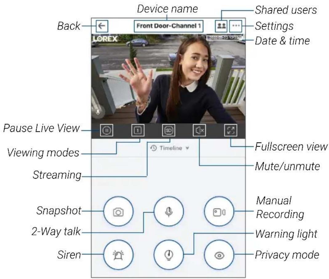
10 Lorex Home app overview
To customize the video doorbell, go to your Lorex Home app and select the doorbell. Tap on the ••• icon on the top right of the screen to access the doorbell's settings.
Person Detection
Tap on Motion Detection Settings to customize person detection. Draw designated areas to alert for person detection and adjust how sensitive the detection level will be.
Activate Status LED on Detection
Tap on Motion Detection Settings > Light Settings to enable Activate Status LED on Detection. The LED color on the doorbell's status indicator can be customized for person detection alert.
Night Light Mode
Tap on Motion Detection Settings > Light Settings to enable Night Light Mode. The LED light below the doorbell will illuminate the front door when it gets dark.
Shared Users
Tap on Shared Users to let family or friends answer live events and view recordings. Any additional users must sign up for a Lorex Home account to be added.
Doorbell Quick Responses
Tap on Doorbell Quick Responses to record or select a pre-recorded voice message. The Lorex video doorbell can speak to a visitor if you're not able to come to the door.
Video Settings
Tap on Video Settings to change HDR (High Dynamic Range) settings and set the video quality. For optimal streaming the video quality is set to 1080p by default.
Camera Live View
Calling screen
For a complete overview of controls available on the Lorex Home app, scan the QR code below using your mobile device's camera.
Listen-in:
Tap to listen-in on a visitor while your audio is muted.
Ignore / end call
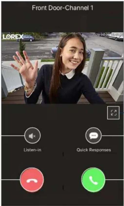
— Fullscreen
Quick responses
Answer call
11 Troubleshooting
1. The video doorbell is not turning on.
• Make sure the breaker is turned back on and wait 5 minutes for the doorbell to fully power on.
- Make sure the power source that supplies the video doorbell is 16-24 VAC. Check if the voltage is printed on your doorbell transformer or use a millimeter to test the voltage.
- Connect the video doorbell using the supplied USB power cable. Make sure the USB cable is connected to a 5V 2A USB power adapter (not included). If the video doorbell powers on with the USB cable, then carefully go over the installation setup again.
2. The video doorbell's chime is not working.
- Make sure to select the correct chime box in the app. You can modify these settings at any time in Device Settings > Doorbell Chime.
- Check to make sure that the chime kit is wired correctly.
- Allow for the video doorbell to power on for 5 minutes before testing the chime.
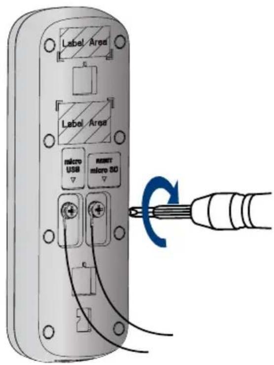
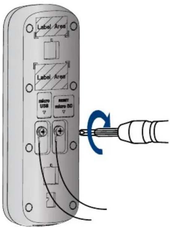
3. How to reset the video doorbell to factory settings.
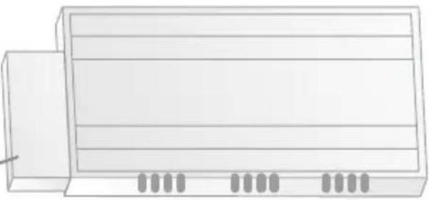
- Pull back the reset/microSD card slot cover located on the back of the video doorbell.
- Use the supplied pin and insert it into the tiny hole labelled RESET for 10 seconds. Wait for an audible sound to confirm that the video doorbell is restarting.
4. How to insert or remove the microSD card from the video doorbell.
- Pull back the reset/microSD card slot cover located on the back of the video doorbell.
- If inserting, slide the microSD card into the slot (with the label side down) until it *clicks* into place.
- If removing, push down gently on the microSD card. It will pop out and can then be removed.
12 Frequently asked questions
1. How come I am receiving so many notifications?
- The amount of notifications you receive can be adjusted in the Lorex Home app for each setting or mode. For example, you can draw Motion Zones for certain areas that you want your doorbell to ignore while effectively monitoring the area you want and reducing false alert notifications. Adjusting Motion Sensitivity will also help.
- You can even manage notifications in Device Settings > Notifications and set a schedule to receive alerts at specific periods in the day.
2. How do I get the video doorbell's light to stay on at night?
In Device Settings > Motion Detection Settings > Light Settings, enable Night Light Mode. Then select Edit Schedule to set a start time and end time for each given day of the week. Make sure to save your settings.
3. How do I record a custom quick response for the video doorbell?
In Device Settings > Doorbell Quick Responses, tap the + on the top right and record your custom quick response. Tap Next to name and save the recorded message.
4. What's the wireless range of the video doorbell?
The video doorbell can only connect to a 2.4 GHz or 5 GHz Wi-Fi network. Many routers broadcast Wi-Fi networks in both 2.4 GHz and 5 GHz bands. During setup, connect your doorbell to the same Wi-Fi network as your phone.
5. What is the USB cable used for?
The USB cable is used to connect to the app before installation. Make sure that the USB cable is connected to a 5V 2A USB power adapter (not included).
Safety precautions:
- Read this guide carefully and keep it for future reference.
- Follow all instructions for safe use and handling of the product.
- Risk of electrical shock. Disconnect the power at the fuse box before installation.
- Use the product within given temperature, humidity and voltage levels noted in the camera's specifications.
- Do not disassemble the doorbell.
- Try to avoid installing the doorbell pointed directly at the sun or a source of intense light.
- Periodic cleaning may be required. Use a damp cloth only. Do not use any harsh, chemical-based cleaners.
Disclaimers:
- The Lorex video doorbell requires a constant power supply with a voltage between 16V-24V. If your residence does not have this voltage, you will need a 16-24 VAC doorbell transformer or you can consult with a licensed electrician.
- Not intended for submersion in water. Installation in a sheltered location recommended.
- This camera includes an Auto Mechanical IR Cut Filter. When the camera changes between Day/Night viewing modes, an audible clicking noise may be heard from the camera. This clicking is normal, and indicates that the camera filter is working.
- Audio recording without consent is illegal in certain jurisdictions. Lorex Corporation assumes no liability for use of its products that does not conform with local laws.
Copyright © 2021 Lorex Corporation
As our products are subject to continuous improvement, Lorex reserves the right to modify product design, specifications and prices, without notice and without incurring any obligation. E&OE. All rights reserved.

This device complies with part 15 of the FCC Rules. Operation is subject to the following two conditions: (1) This device may not cause harmful interference, and (2) This device must accept any interference received, including interference that may cause undesired operation.
For up-to-date information and support please visit:
help.lorex.com
For more information about Lorex's warranty policy, visit lorex.com/warranty.
B451AJ_QSG_TRILINGUAL_R1
LOREX®
natural_image
Illustration of a remote control device with a green square button (no text or symbols)O Bleu fixe
natural_image
Simple curved line diagram with two curved ends and a gray top (no text or symbols)natural_image
Diagram of a device with a green connector and red wires, labeled Figure 2 (no text or symbols on the diagram itself)Figure 1

natural_image
Technical diagram of an electrical circuit with transformers, capacitors, and insulators (no text or labels)Figure 4
natural_image
Illustration of a rectangular electronic device with ventilation slots and a side panel (no text or symbols)
Remarques :
natural_image
Diagram of two electrical connectors with pliers, labeled Figure 1 (no text or symbols on components)Figure 2
natural_image
Diagram of two electrical outlet switches with black cables and circular components (no text or symbols)Figure 4

natural_image
Diagram of a device showing internal components connected to a screen, with no visible text or symbols.
natural_image
Illustration of a white electric shaver with label 'Figure 2' (no other text or symbols)Plein écran
réponses rapides
Répondre à un appel
11 Dépannage
Copyright © 2021 Lorex Corporation
natural_image
Front view of a mobile phone with a green square button on the side (no text or symbols visible)Azul fijo
Figura 2

natural_image
Simple curved line diagram with two ends and a cloud-like shape at the top (no text or symbols)natural_image
Diagram of a rectangular block with a green internal component connected to three red wires, labeled 'Figura 2' (no text or symbols on the diagram itself)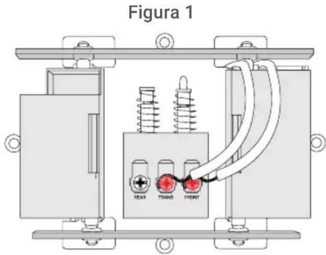
natural_image
Technical diagram of an electrical transformer with insulators and wiring (no text or labels)Figura 4
natural_image
Illustration of a rectangular electronic device with ventilation slots and a pointer, no text or symbols present.natural_image
Close-up of electrical plug connectors with no visible text or symbolsFigura 2
natural_image
Diagram of two electrical outlet switches with black cables and circular components (no text or symbols)Figura 4
natural_image
Diagram of a device showing internal components connected to a screen, with no visible text or symbols.
natural_image
Close-up of a white industrial blender with a handle and label (no visible text or symbols)Copyright © 2021 Lorex Corporation


- Contents
- Package contents
- User-supplied tools
- Overview
- ③ Status indicator
- Solid blue
- Solid red
- Solid green
- Flashing blue slowly
- Flashing blue rapidly
- Flashing red
- Flashing green
- Flashing blue, red, and green
- Spinning red
- Spinning green
- Connect to the app
- Connect to the Lorex Home app to access the doorbell's installation videos.
- Preparation
- To prepare for installation:
- Step 1
- Step 2
- Wiring the chime
- For mechanical chime owners:
- Secure the mounting bracket(s)
- Step 1: Mark mounting holes
- Step 2 (Optional): Attach an angled bracket to the mounting bracket
- Notes:
- Step 3: Secure the mounting bracket
- For wood, drywall or soft surfaces:
- For concrete, stucco or brick:
- ⑧ Wiring the doorbell
- To wire the doorbell:
- To extend short wires (optional):
- Connect the doorbell
- To attach the doorbell to the bracket:
- Note - If you need to remove the doorbell from the bracket:
- Lorex Home app overview
- Person Detection
- Activate Status LED on Detection
- Night Light Mode
- Shared Users
- Doorbell Quick Responses
- Video Settings
- Calling screen
- Troubleshooting
- The video doorbell is not turning on.
- The video doorbell's chime is not working.
- How to reset the video doorbell to factory settings.
- How to insert or remove the microSD card from the video doorbell.
- Frequently asked questions
- How come I am receiving so many notifications?
- How do I get the video doorbell's light to stay on at night?
- How do I record a custom quick response for the video doorbell?
- What's the wireless range of the video doorbell?
- What is the USB cable used for?
- Safety precautions:
- Disclaimers:
- LOREX®
- O Bleu fixe
- Remarques :
- Dépannage
- Azul fijo
Brand : Lorex
Model : B451AJD-EG
Category : Doorbells