
ILB6 - Range hood BEST - Free user manual and instructions
Find the device manual for free ILB6 BEST in PDF.

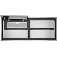
| Product Type | Ducted Range Hood |
| Brand | Best |
| Model | ILB6 |
| Usage | General kitchen ventilation, smoke and grease removal |
| Power Supply | 120 V, 60 Hz (dedicated circuit with GFCI recommended) |
| Duct Type | Round 10 in (25.4 cm) or rectangular 8 x 12 in (20.3 x 30.5 cm) |
| Mounting Options | New or existing construction, cable suspension, joist supports |
| Discharge Positions | In-line (horizontal) or right angle (vertical), adjustable |
| Cabinet Dimensions (approx.) | Length: 55.9 cm, Width: 45.7 cm, Height: 2.9 to 6.4 cm (adjustable) |
| Estimated Weight | Approximately 11 kg (25 lb) |
| Material | Painted steel (housing), metal (ducts) |
| Filter | Washable metal mesh (regular cleaning recommended) |
| Motor | Lubricated for life, maintenance-free |
| Sound Level | Not specified (typical for this type: 40-60 dB) |
| Maintenance | Clean filters regularly; vacuum blower without water entering motor |
| Safety | Grounding required; disconnect power before service; do not use for explosive vapors |
| Warranty | 1 year (limited, parts and labor) |
| Replacement Parts | Available (see list in manual): motor, wheel, damper, filters, etc. |
| Repairability | Designed to be repaired by a professional; standardized parts available |
| Box Contents | Cabinet, blower, suspension kit, duct transitions, hardware |
Frequently Asked Questions - ILB6 BEST
User questions about ILB6 BEST
0 question about this device. Answer the ones you know or ask your own.
Ask a new question about this device
Download the instructions for your Range hood in PDF format for free! Find your manual ILB6 - BEST and take your electronic device back in hand. On this page are published all the documents necessary for the use of your device. ILB6 by BEST.
USER MANUAL ILB6 BEST
READ AND SAVE THESE INSTRUCTIONS

-
Use this unit only in the manner intended by the manufacturer. If you have questions, contact the manufacturer at the address or telephone number listed in the warranty.
-
Before servicing or cleaning unit, switch power off at service panel and lock the service disconnecting means to prevent power from being switched on accidentally. When the service disconnecting means cannot be locked, securely fasten a prominent warning device, such as a tag, to the service panel.
-
Installation work and electrical wiring must be done by a qualified person(s) in accordance with all applicable codes and standards, including fire-rated construction codes and standards.
-
Sufficient air is needed for proper combustion and exhausting of gases through the flue (chimney) of fuel burning equipment to prevent backdrafting. Follow the heating equipment manufacturer's guideline and safety standards such as those published by the National Fire Protection Association (NFPA), and the American Society for Heating, Refrigeration and Air Conditioning Engineers (ASHRAE), and the local code authorities.
-
When cutting or drilling into wall or ceiling, do not damage electrical wiring and other hidden utilities.
-
Ducted fans must always be vented to the outdoors.
-
To reduce the risk of fire, use only metal ductwork.
-
If this unit is to be installed over a tub or shower, it must be marked as appropriate for the application and be connected to a GFCI (Ground Fault Interrupter) - protected branch circuit.
-
Never place a switch where it can be reached from a tub or shower.
-
This unit must be grounded.
TO REDUCE THE RISK OF A RANGE TOP GREASE FIRE:
-
Never leave surface units unattended at high settings. Boilovers cause smoking and greasy spillovers that may ignite. Heat oils slowly on low or medium settings.
-
Always turn hood ON when cooking at high heat or when flambe-ing food (i.e. Crepes Suzette, Cherries Jubilee, Peppercorn Beef Flambe').
-
Clean ventilating fans frequently. Grease should not be allowed to accumulate on fan or filter.
-
Use proper pan size. Always use cookware appropriate for the size of the surface element.
TO REDUCE THE RISK OF INJURY TO PERSONS IN THE EVENT OF A RANGE TOP GREASE FIRE, OBSERVE THE FOLLOWING:\*
-
SMOTHER FLAMES with a close-fitting lid, cookie sheet, or metal tray, then turn off the burner. BE CAREFUL TO PREVENT BURNS. If the flames do not go out immediately, EVACUATE AND CALL THE FIRE DEPARTMENT.
-
NEVER PICK UP A FLAMING PAN - You may be burned.
-
DO NOT USE WATER, including wet dishcloths or towels - violent steam explosion will result.
WARNING


- Use an extinguisher ONLY if:
A. You know you have a Class ABC extinguisher and you already know how to operate it.
B. The fire is small and contained in the area where it started.
C. The fire department is being called.
D. You can fight the fire with your back to an exit.
* Based on "Kitchen Fire Safety Tips" published by NFPA.
CAUTION

- For general ventilating use only. Do not use to exhaust hazardous or explosive materials and vapors.
2 To avoid motor bearing damage and noisy and/or unbalanced impellers, keep drywall spray, construction dust, etc. off power unit.
-
If ventilator is installed in an unconditioned space (such as an attic): Surround the ventilator with thermal insulation - to minimize possible condensation.
-
Please read specification label on product for further information and requirements.
TABLE OF CONTENTS
This manual is divided into sections as follows:
• "TYPICAL INSTALLATION"
This section shows a common installation.
- Mounting (New Frame Construction)
- Mounting (Existing Frame Construction)
- Mounting Using Hanger Kit (included)
- Ducting (Horizontal blower discharge)
- Wiring
• "MOUNTING OPTIONS"
• "WIRING PLATE POSITION"
• "DUCTING OPTIONS"
- Blower Discharge Positions
- Ducting (Vertical blower discharge)
• "USE AND CARE"
• "SERVICE PARTS"
- "WARRANTY"
Installer: Leave this manual with the homeowner.
Homeowner: Use and Care information on page 4.
TYPICAL INSTALLATION
MOUNTING (New Frame Construction)
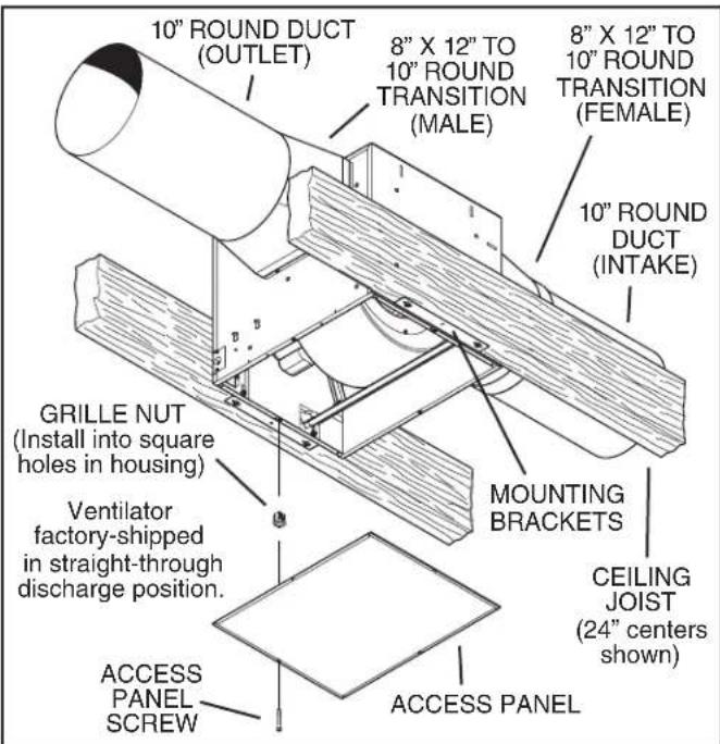
Factory-shipped unit installed in new construction.
MOUNTING (Existing Frame Construction)
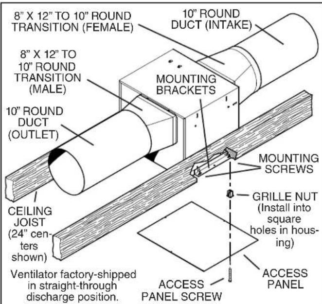
Factory-shipped unit installed in existing construction.
IMPORTANT: Remove shipping tape from damper Remove the shipping tape from the damper flap and make sure that damper flap opens and closes freely inside the ductwork. Use duct tape to make ductwork connections secure and air-tight.
TYPICAL INSTALLATION
MOUNTING USING HANGER KIT (included)
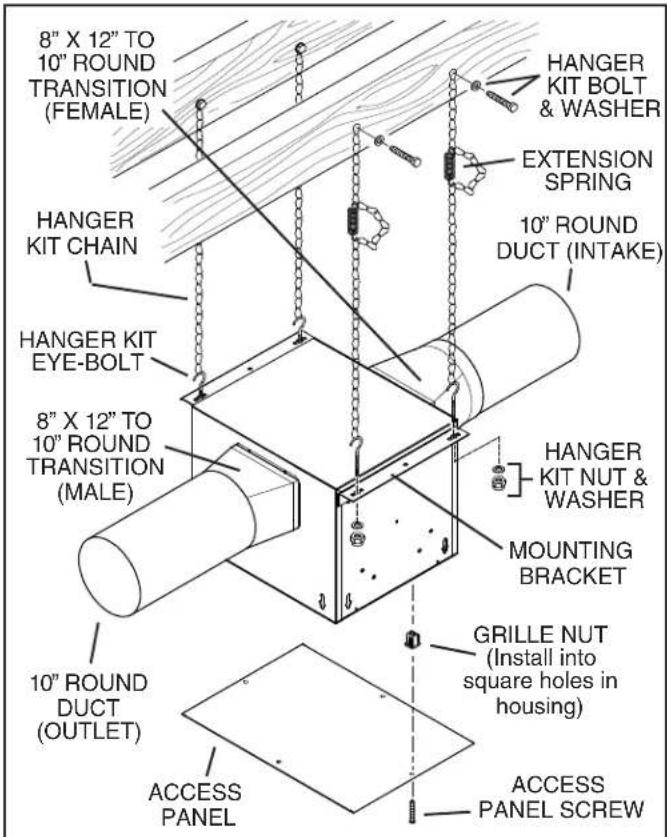
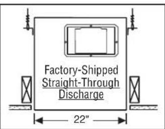
Blower factory-shipped in straight-through discharge position.
DUCTING (Horizontal blower discharge)
Two ways to connect ductwork to a factory-shipped unit.
WIRING
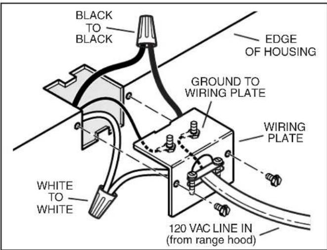
Ventilator can be wired from outside of housing. Use UL approved connectors to wire per local codes.
MOUNTING OPTIONS
14 -20 hex nuts secure mounting brackets to housing. Loosen and re-tighten or remove and replace nuts as necessary for desired mounting bracket position.
Mounting brackets in factory-shipped position - mounted directly to joists. (Outlet parallel to joists.) (New construction)
Mounting brackets flipped over and mounted to additional framing. (Outlet perpendicular to joists.) (New or Existing construction)
Mounting brackets flipped over and mounted to additional framing. (Outlet vertical.) (New or Existing construction)
Mounting brackets flipped over and mounted to top of housing. Housing secured with cables. (Outlet parallel to joists.) (New or Existing construction)
WIRING PLATE POSITION
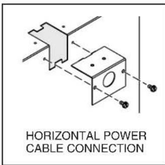
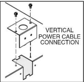
Wiring plate mounts to side or top of housing.
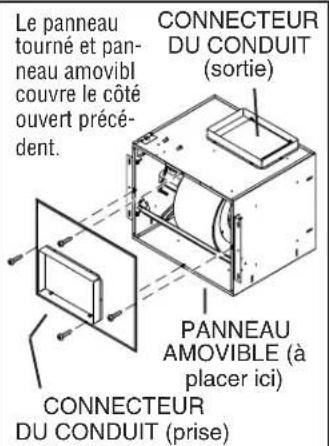
DUCTING OPTIONS
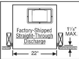
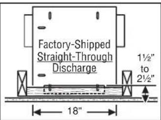
BLOWER DISCHARGE POSITIONS
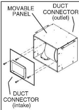
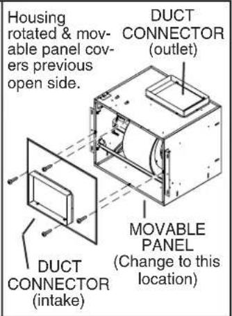
Ventilator shown in straight-through discharge position. (Factory shipped)
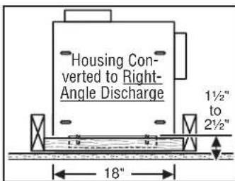
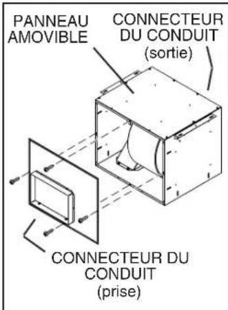
Ventilator shown in right-angle discharge position. (Change movable panel to new location as shown.)
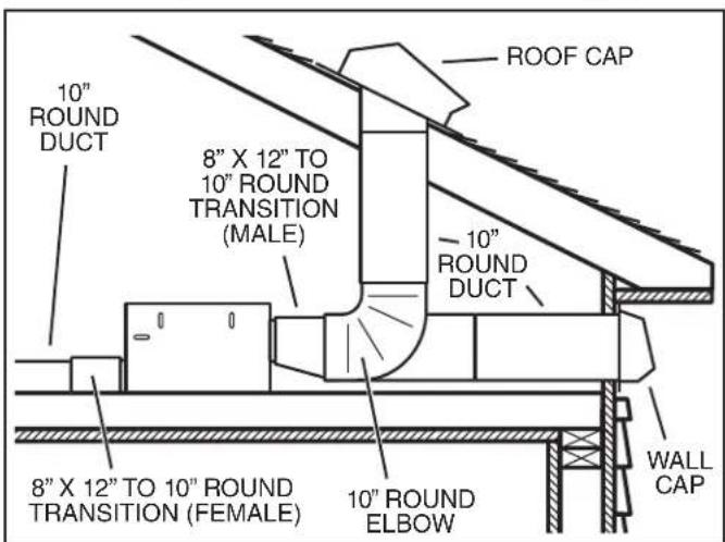
DUCTING (Vertical blower discharge)
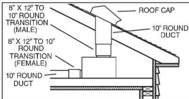
Typical ductwork connection to a ventilator converted to right-angle discharge.
USE AND CARE
Follow wiring instructions packed with range hood, and adhere to all local and state codes, and the National Electrical Code.

WARNING: To reduce the risk of electric shock, disconnect from power supply before servicing.
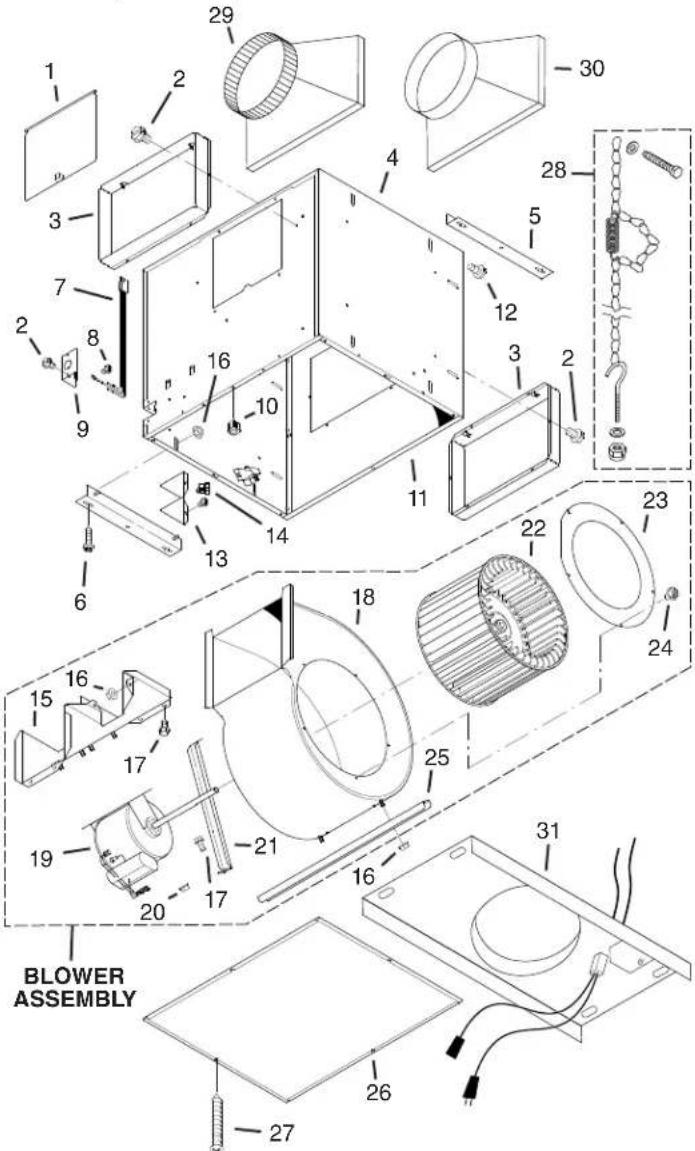
SERVICE PARTS
| KEY NO. | PART NO. | DESCRIPTION |
| 1 970148 | 53 Damper | Flap |
| 2 991504 | 15 Screw, #8B x 14 * (16 req.) | |
| 3 980095 | 20 Duct Connector (2 req.) | |
| 4 970147 | 84 Housing Assembly | |
| 5 970147 | 28 Mounting Bracket (2 req.) | |
| 6 991505 | 91 Mounting Screw, #10-12 x .625 (4 req.) | |
| 7 970061 | 42 Wiring Harness | |
| 8 991504 | 71 Ground Screw, #10-32 x 12 * (2 req.) | |
| 9 980055 | 12 Wiring Adapter Plate | |
| 10 99420 | 470 Access Panel Nut (4 req.) | |
| 11 98009 | 531 Movable Housing Panel | |
| 12 93150 | 487 Screw, #10-24 x .375* (8 req.) | |
| 13 98005 | 513 Outlet Box Cover | |
| 14 99400 | 035 Strain Relief Bushing | |
| 15 97014 | 788 Motor Bracket | |
| 16 99260 | 477 Whiz Nut, 14 -20* (11 req.) | |
| 17 99200 | 202 Screw, 14 -20 x 12 * (5 req.) | |
| 18 97014 | 785 Blower Scroll | |
| 19 99080 | 490 Motor (ILB9) | |
| 99080491 Motor (ILB11) | ||
| 20 93260447 Nut, Hex Flange 5/16-18* (5 req.) | ||
| 21 98009516 Support Bracket | ||
| 22 99020286 Blower Wheel | ||
| 23 98009514 Inlet Ring | ||
| 24 99150417 Screw, #8-18 x 14 * (5 req.) | ||
| 25 98009513 Scroll Support Channel | ||
| + 970167 | 94 Blower Assembly Complete (ILB9) | |
| (Includes Key Nos. 15 thru 25) | ||
| + 970167 | 95 Blower Assembly Complete (ILB11) | |
| (Includes Key Nos. 15 thru 25) | ||
| 26 98009532 Access Cover | ||
| 27 99150472 Access Cover Screw (4 req.) | ||
| 28 97016791 Hanger Kit | ||
| 29 99610015 Transition, 8" x 12" to 10" Round, Male | ||
| 30 99610028 Transition, 8" x 12" to 10" Round, Female | ||
| 31 97014597 Rough-In Kit |
Order replacement parts by PART NO. - not by KEY NO.
Standard hardware - may be purchased locally.
+ Not shown assembled.
WARRANTY
To clean blower assembly: Remove access panel, unplug blower from housing, remove blower mounting nuts, and carefully remove blower from housing. Use appropriate vacuum attachment or a soft cloth and mild soap or detergent to clean blower discharge area and wheel. DO NOT ALLOW WATER TO ENTER MOTOR. Make sure blower assembly is completely dry before reinstalling.
Motor is permanently lubricated. Do not oil or disassemble motor.
ONE YEAR LIMITED WARRANTY FOR BEST PRODUCTS
Broan-NuTone LLC (Broan-NuTone) warrants to the original consumer purchaser of Best products that such products will be free from defects in materials or workmanship for a period of one year from the date of original purchase. THERE ARE NO OTHER WARRANTIES, EXPRESS OR IMPLIED, INCLUDING, BUT NOT LIMITED TO, IMPLIED WARRANTIES OR MERCHANTABILITY OR FITNESS FOR A PARTICULAR PURPOSE. During this one-year period, Broan-NuTone will, at its option, repair or replace, without charge, any product or part which is found to be defective under normal use and service.
THIS WARRANTY DOES NOT EXTEND TO FLUORESCENT LAMP STARTERS, TUBES, HALOGEN AND INCANDESCENT BULBS, FUSE, FILTERS, DUCTS, ROOF CAPS, WALL CAPS AND OTHER ACCESSORIES FOR DUCTING. This warranty does not cover (a) normal maintenance and service or (b) any products or parts which have been subject to misuse, negligence, accident, improper maintenance or repair (other than by Broan-NuTone), faulty installation or installation contrary to recommended installation instructions.
The duration of any implied warranty is limited to the one-year period as specified for the express warranty. Some states do not allow limitation on how long an implied warranty lasts, so the above limitation may not apply to you.
BROAN-NUTONE'S OBLIGATION TO REPAIR OR REPLACE. AT BROAN-NUTONE'S OPTION, SHALL BE THE PURCHASER'S SOLE AND EXCLUSIVE REMEDY UNDER THIS WARRANTY. BROAN-NUTONE SHALL NOT BE LIABLE FOR INCIDENTAL, CONSEQUENTIAL OR SPECIAL DAMAGES ARISING OUT OF OR IN CONNECTION WITH PRODUCT USE OR PERFORMANCE. Some states do not allow the exclusion or limitation of incidental or consequential damages, so the above limitation or exclusion may not apply to you.
This warranty gives you specific legal rights, and you may also have other rights, which vary from state to state. This warranty supersedes all prior warranties.
To qualify for warranty service, you must (a) notify Broan-NuTone at the address or telephone number stated below, (b) give the model number and part identification and (c) describe the nature of any defect in the product or part. At the time of requesting warranty service, you must present evidence of the original purchase date.
In USA: BEST ^® , 926 W. State Street, Hartford, Wisconsin 53027 800-558-1711 In Canada: BEST ^® , 550 Lemire Blvd., Drummondville (Quebec) Canada J2C 7W9 866-737-7770 www.BestRangeHoods.com
VENTILADORES PARA MONTAJE EN LÍNEA
LEA Y CONSERVE ESTAS INSTRUCCIONES

PARA COCINAR EN CASA SOLAMENTE

ADVERTENCIA


OPTIONS D'INSTALLATION DES CONDUITS
POSITIONS DE LA DÉCHARGE DE LA SOUFFLERIE
Aux E.U.: BEST®, 926 W. State Street, Hartford, Wisconsin 53027 800-558-1711 Au Canada: BEST®, 550 Lemire Blvd., Drummondville (Quebec) Canada J2C 7W9 866-737-7770 www.BestRangeHoods.com

- READ AND SAVE THESE INSTRUCTIONS
- TO REDUCE THE RISK OF A RANGE TOP GREASE FIRE:
- TO REDUCE THE RISK OF INJURY TO PERSONS IN THE EVENT OF A RANGE TOP GREASE FIRE, OBSERVE THE FOLLOWING:\*
- WARNING
- CAUTION
- TABLE OF CONTENTS
- Installer: Leave this manual with the homeowner.
- Homeowner: Use and Care information on page 4.
- TYPICAL INSTALLATION
- WIRING
- MOUNTING OPTIONS
- WIRING PLATE POSITION
- DUCTING OPTIONS
- BLOWER DISCHARGE POSITIONS
- DUCTING (Vertical blower discharge)
- USE AND CARE
- WARRANTY
- ONE YEAR LIMITED WARRANTY FOR BEST PRODUCTS
- VENTILADORES PARA MONTAJE EN LÍNEA
- LEA Y CONSERVE ESTAS INSTRUCCIONES
- PARA COCINAR EN CASA SOLAMENTE
- ADVERTENCIA
- OPTIONS D'INSTALLATION DES CONDUITS
Brand : BEST
Model : ILB6
Category : Range hood