S-ZPK 30 KS - Water pump Zehnder Pumpen - Free user manual and instructions
Find the device manual for free S-ZPK 30 KS Zehnder Pumpen in PDF.


User questions about S-ZPK 30 KS Zehnder Pumpen
0 question about this device. Answer the ones you know or ask your own.
Ask a new question about this device
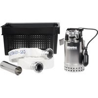
Download the instructions for your Water pump in PDF format for free! Find your manual S-ZPK 30 KS - Zehnder Pumpen and take your electronic device back in hand. On this page are published all the documents necessary for the use of your device. S-ZPK 30 KS by Zehnder Pumpen.
USER MANUAL S-ZPK 30 KS Zehnder Pumpen
line
| Q(m³/h) | H(m) for ZPK 35 | H(m) for ZPK 40 | H(m) for ZPK 30 | | ------- | --------------- | --------------- | --------------- | | 0 | 11.0 | 10.0 | 8.0 | | 2 | 10.5 | 9.5 | 7.0 | | 4 | 10.0 | 9.0 | 6.0 | | 6 | 9.5 | 8.5 | 5.0 | | 8 | 9.0 | 8.0 | 4.0 | | 10 | 8.5 | 7.5 | 3.0 | | 12 | 8.0 | 7.0 | 2.0 |text_image
Technical cross-sectional diagram of a mechanical device with numbered components for identification.ZPK 30 A / ZPK 35 A
text_image
Technical cross-sectional diagram of a mechanical device with numbered components for identification.ZPK 40 A
© 2012 by Zehnder GmbH
Nur für EU-Länder
Table of contents 13
Declaration of conformity....13
- General....14
1.1 Introduction ...... 14
1.2 Enquiries and orders.... 14
1.3 Technical data.... 14
1.4 Range of application 15
1.5 Accessories 15
- Safety 15
2.1 Marking of the notes contained in the operation manual 15
2.2 Personnel development and training 15
2.3 Dangers in case of non-observance of the safety notes 16
2.4 Safety-conscious way of working 16
2.5 Safety notes for the operator/user 16
2.6 Safety notes concerning maintenance, inspection and assembly works ..... 16
2.7 Unauthorised modification and fabrication of spare parts 16
2.8 Unauthorised modes of operation 17
-
Description.... 17
-
Installation and Commissioning.... 17
-
Maintenance 18
-
Malfunctions; causes and elimination 18
-
Warranty....18
-
Technical modifications .... 19
-
Characteristics....19
-
Example of installation – stationary installation .... 19
-
Sectional drawing and spare parts list ZPK 30 A / ZPK 35 A 20
-
Sectional drawing and spare parts list ZPK 40 A 22
Declaration of conformity
that the submersible motor pumps of the type series ZPK
conform to the following relevant regulations in the respectively valid versions:
- EC low voltage directive 2014/35 EU
- EMC directive 2014/30 EU
- Machinery directive 2006/42/EC
Applied harmonised standards, particularly
EN 60335-1:2012/A11:2014
EN 60335-2-41:2003/A2:2010
EN 809:1998/AC:2010
EN 55014-1:2006/A2:2011, EN 55014-2:1997/A2:2008
EN 61000-3-2:2014, EN 61000-3-3:2013
EN 61000-6-1:2007, EN 61000-6-2:2005, EN 61000-6-3/A1:2011, EN 61000-6-4/A1:2011
Grünhain, 28/10/2016
Matthas Kotte
Product development
OM: ZPK English
State: 2011
1. General
1.1 Introduction
This operation manual is valid for the submersible pumps of the type series ZPK.
If the instructions of the operation manual – especially the safety instructions - are not observed, or in case of unauthorized modifications of the device or the installation of non-original spare parts, the guarantee expires automatically. The manufacturer assumes no liability for damages resulting from such behaviour!
Such as any other electrical device, this product may fail due to absence of mains voltage or a technical failure. If damage could occur, an emergency power supply, a second plant and/or an off-grid alarm device should be provided according to the application. We as manufacturer are at your disposal for consultation also after the purchase. In case of failures or damages, please contact your retailer.
Manufacturer: ZEHNDER Pumpen GmbH
Zwönitzer Straße 19
Date of manufacture: The date of manufacture of the pump is engraved on the top of the housing.
Manufactured sizes: Drainage pump ZPK 30 / ZPK 35 / ZPK 40
Design A with floating_switch, design KS with compact floater
State of the operation manual: 2011
1.2 Enquiries and orders
In case of enquiries or orders, address yourself to your retailer and/or specialist retailer.
1.3 Technical data
| ZPK 30 | ZPK 35 | ZPK 40 | |
| Pressure connection | G 114 “ AG | ||
| max. particle size | 10 mm | 10 mm | 30 mm |
| Voltage | 230 V | ||
| Frequency | 50 Hz | ||
| Rated input P1 | 300 W | 850 W | 850 W |
| Nominal output P2 | 130 W | 430 W | 430 W |
| Power input | 1.3 A | 3.7 A | 3.7 A |
| Rotational speed | 2800 min^-1 | ||
| Mains connection line | 10 m, 3 x 1 mm ^2 | ||
| Floating switch | yes | yes | yes |
| max. discharge flow | 7,000 l/h | 11,000 l/h | 10,000 l/h |
| max. discharge height | 7.5 m | 11 m | 10 m |
| Weight with cable | 4.4 kg | 6.6 kg | 6.6 kg |
| Diameter | 150 mm | ||
| Total height | 270 mm | 300 mm | 345 mm |
| max. submersion depth | 5 m | 5 m | 5 m |
Materials:
Pump housing: Polypropylene (PP) Running wheel: PA 6
Motor recept. housing: Polypropylene (PP) Floating switch: Polypropylene (PP)
Bottom filter: Polyethylene (PE) Screws: Stainless steel 1.4301
Motor housing:
Stainless steel 1.4301
Mechanical seal:
Carbon/Ceramics
The submersible pumps of the type series ZPK are applicable up to a liquid temperature of 40 °C , short-term up to 70 °C .
1.4 Range of application
The pumps of the type series ZPK are adapted for the discharge of slightly polluted liquids with suspended solids (no stones) from private homes, in the industrial sector and agriculture.
The dimension of the suspended solids must not exceed the maximum grit size as mentioned in point
1.3. The pumps must not be used for the discharge of sewages containing excrements.
1.5 Accessories
The pumps of the type series ZPK are delivered with an outlet bend with a nut connector (1¼"), to which a hose (1" in case of ZPK 30, 1¼" in case of ZPK 35 and ZPK 40) may be connected.
As optional accessory (not included in scope of delivery) a retrofit kit, outlet bend with non-return valve, with the article number 17016 is available. This is preassembled and consists of:
Bend 90° 1 1/4" IG/AG, non-return valve 1 1/4", straight hose nozzle 1 1/4" with seal for a hose diameter of 25 and 32 mm.
Furthermore, the pumps market with "A" are equipped with a floating switch and the pumps marked with "KS" are equipped with a compact floating switch for confined spaces.
2. Safety
(from: "VDMA sheet 24 292")
The operation manual at hand provides basic notes which must be taken into account during assembly, operation and maintenance works. Therefore, before assembly and commissioning, this operation manual must be read by the assembler as well as by the responsible personnel/operator at all costs. It always must be available on site of operation of the device.
The general safety notes listed under the main point safety are not the only notes to be taken into account. Please also observe the specific safety instructions, such as those for private use, listed under other main points.
2.1 Marking of the notes contained in the operation manual
The safety notes contained in this operation manual which can cause danger to persons are specifically marked by the following general danger symbol

Safety sign according to DIN 4844 - W 9
The following symbol warns against dangers caused by voltage
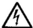
Safety sign according to DIN 4844 - W 8
In case of safety notes the non-observance of which can cause danger to the device and its functioning, the word ATTENTION! is inserted.
Notes that are directly attached to the device, such as - Arrow indicating the direction of rotation - Characteristics of liquid connections
must be observed and kept in completely readable condition at all costs.
2.2 Personnel development and training
The personnel responsible for operation, maintenance, inspection and assembly must have the corresponding qualifications for those types of work. Area of responsibility, competence and the surveillance of the personnel must be regulated precisely by the operator. If the personnel do not possess the necessary knowledge, they must be trained and instructed. By order of the operator of the pump, the instruction and training, if necessary, can be carried out by the manufacturer/supplier. Furthermore the operator must make sure that the personnel have completely understood the content of the operation manual.
2.3 Dangers in case of non-observance of the safety notes
The non-observance of the safety notes can cause dangers to persons as well as to the environment and the machine. If the safety notes are not observed, this can result in the loss of all compensation claims.
In detail, non-observance can for instance result in the following damages as an example:
- Failure of important functions of the pump
- Failure of the prescribed methods for maintenance and repair
- Endangerment of persons through electrical, mechanical and chemical influences
- Endangerment of the environment through leakage of hazardous substances
2.4 Safety-conscious way of working
The safety notes listed in this operation manual, the existent national regulations on accident prevention as well as possible internal working, operating, and safety instructions of the operator must be observed.
2.5 Safety notes for the operator/user

- Hot or cold device components which could cause danger must be secured against contact by the customer.
- The pumps are equipped with a thermal winding cover, if the motor cools down, the pump starts automatically. Due to this fact, the device must be disconnected from mains during repair or maintenance works!
- Protection against contact with moving parts (e.g. coupling) must not be removed while the machine is operating.
- Leakages (e.g. of the shaft sealing) of hazardous materials to be conveyed (e.g. explosive, toxic, hot) must be discharged in such a way that no danger arises for persons or the environment. The legal requirements must be observed.
- Endangerments through electric power must be eliminated (details concerning this, see e.g. the regulations of the VDE (German Association for Electrical, Electronic and Information Technology) and the local energy suppliers).
2.6 Safety notes concerning maintenance, inspection, and assembly works
The operator must make sure that all maintenance, inspection, and assembly works are carried out by authorised, skilled, and qualified personnel which are adequately informed by having thoroughly studied the operation manual.
Only use original spare parts.
Generally, works on the machine are only to be carried out when the pump is turned off. The proceeding prescribed in the operation manual in order to stop the pump must be respected at all costs.
Pumps or pump units conveying media dangerous to health must be decontaminated. Immediately after finalising the works, all safety and protection installations must be reinstalled and/or activated.
Before restart, the points listed in the chapter commissioning must be taken into consideration.
2.7 Unauthorised modification and fabrication of spare parts
Retrofitting and modifications of the switching device are permitted only after having consulted the manufacturer. Original spare parts and accessories authorised by the manufacturer ensure the safety. The use of other parts can lead to the removal of liability for the resulting damages.
2.8 Unauthorised modes of operation
The operational reliability of the machine is only guaranteed, if it is used as intended according to chapter 1 – General. The limit values stated in the data sheet must not be exceeded.
Attention
Also a device operating automatically such as a submersible pump must not be operated without supervision for a longer time period.
3. Description
The pumps of the type series ZPK are equipped with a sturdy alternating current motor; the sealing of the pump housing to the motor is executed using a mechanical seal. The current is connected using the 10 m long connecting cable with 230 V-50 Hz alternating current.

- The pump must be connected to a socket with earthing.
- Never carry the pump on the cable, never low it on cable into the water; never pull it on cable out of the water.
- If the power is not supplied obligatory via an earth leakage circuit breaker with maximum measured residual current 30 mA, the pump must be connected via a separate earth leakage circuit breaker to the socket

The use of the pump at swimming pools and garden ponds and within their protection zones is only permitted if the plants located there are installed according to DIN VDE 0100/part 702. It is forbidden to take a bath in the pool during operation of the pump. Ask your professional electrician.
4. Installation and commissioning

Before commissioning of the pump, check it for possible external damages (e.g. transport damages), in order to prevent accidents with electrical power.
In order to ensure an excellent working of the pump, the following minimum water levels are required:
ZPK 30: 120 mm (discharges to 25 mm)
ZPK 35: 160 mm (discharges to 25 mm)
ZPK 40: 200 mm (discharges to 45 mm)
If the pump shall be used in a cavity or a shaft the shaft/cavity must have a minimum dimension of 450 x 450 x 450 mm. The suction basket must not be blocked by sludge and/or media containing fibres. The floating switch attached to the pump (pumps marked with A or KS) must be freely moveable. . If the water level raises, the floater floats, switches the pump on and discharges the water until the water level is low that the floater switches the pump off. The switching- on and switching-off height of the floater can be varied by displacing the floater cable inside of the mounting eye or, in case of a KS floater, by displacing the float body. The function of the floater can be checked by lifting and lowering. In case of pumps without floating switch, the pumping process starts with connecting the plug to the socket. The water leakage between the two parts of the housing is normal, due to the fact that there is pump ventilation.

- In order to prevent damage to the mechanical seal, the pump must not run dry.
5. Maintenance

Disconnect the power supply before carrying out any kind of work on the pump and protect it against unauthorised reconnection!
Maintenance contains an inspection and a cleaning of the pump housing. For this purpose loosen the four cross-head screws (pos. 24 of the sectional drawing), remove and clean the inlet filter (pos. 3) and the base plate (pos. 4). Subsequently, reassemble all parts in the right order.
ATTENTION In case of a worn running wheel (e.g. due to abrasive media) a wear of the mechanical seal is also possible. The inspection of the mechanical seal and the motor as well as the replacement of the electric connecting cable should be effected by authorised after-sales services or by manufacturing factory only.
6. Malfunctions; causes and elimination

- Disconnect the power supply before carrying out any kind of work on the ejection unit!
| Failure | Cause | Removal |
| 1. No motor rotation | - Mains voltage missing or faulty | - Check power supply |
| - Incorrect connection | - Correct the connection | |
| - Defective current cable | - Replacement (after-sales-service) | |
| - Running wheel is blocked | - Cleaning | |
| - Activated motor protection (over-heating, blockage, voltage failure or other defect) | Check, inform the after-sales-service | |
| - Floater got stuck | - Position the pump in such a way that the floater can work freely | |
| - Motor is defective | - Replacement (after-sales-service) | |
| 2. Motor rotates but does not con-vey | - Running wheel is blocked or worn | - Cleaning/Replacement |
| - Pressure pipe is blocked/hose is bended | - Clean/remove kinks | |
| - Intake socket is blocked | - Clean | |
| 3. Discharge flow is too low | - Pump is not properly bled (air bubble inside of the housing) | - Bleed the pressure pipe during initial commissioning of the pipe, so that water reaches the pump hous-ing |
| 4. Discharge flow is too low | - Too small dimension of the pressure pipe | - min. diameter 25 mm (1“) |
7. Warranty
As manufacturer, for all pumps of the type series ZPK we provide a warranty of 24 months from date of purchase. Your sales receipt passes for verification. During that warranty period, we gratuitously remedy all deficiencies which are attributed to material or fabrication defects by either repairing or replacing the pump (to our choice).
Defects which are attributed to misuse or wear (running wheel and shaft seal) are excluded from warranty.
Furthermore, the warranty claim expires if works (excepting those under point 5) are effected on the pump. We will assume no responsibility for consequential damages that are caused by a breakdown of the pump.
8. Technical modifications
Technical modifications are reserved for the purpose of further development.
9. Characteristics
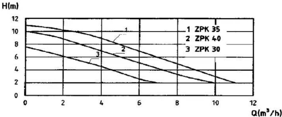
line
| Q(m³/h) | H(m) for ZPK 35 | H(m) for ZPK 40 | H(m) for ZPK 30 | | ------- | --------------- | --------------- | --------------- | | 0 | 12 | 10 | 8 | | 2 | 10 | 8 | 6 | | 4 | 8 | 6 | 4 | | 6 | 6 | 4 | 2 | | 8 | 4 | 2 | 0 | | 10 | 2 | 0 | 0 | | 12 | 0 | 0 | 0 |10. Example of installation – stationary installation
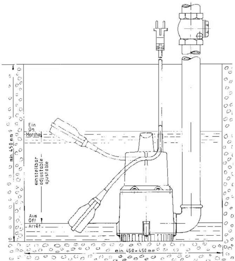
text_image
Ein On Marchel einstellbar adjustable- adjustable Aus Off Arrêt min. 450×450 mm min. 450×450 mm11. Sectional drawing and spare parts list ZPK 30 A / ZPK 35 A

text_image
Technical cross-sectional diagram of a mechanical device with numbered components for identification.ZPK 30 A / ZPK 35 A
| Pos. | Designation | Quantity | Order number |
| 1 | Pump housing 207/00 yellow | 1 | 272091.2 |
| 2 | Motor reception housing 1-hole (without floater) | 1 | 270002.1 |
| 2 | Motor reception housing 2-hole (with floater) | 1 | 270002.2 |
| 3 | Bottom filter | 1 | 272093.4 |
| 4 | Base plate | 1 | 272094 |
| 5 | Running wheel d = 90 mm (ZPK 30) | 1 | 272405.R |
| 5 | Running wheel d = 100 mm (ZPK 35) | 1 | 272905.R |
| 11 | Condenser 5 μF (ZPK 30) | 1 | 900134 |
| 11 | Condenser 8 μF (ZPK 35) | 1 | 279911 |
| 12 | Fixation piece | 1 | 270012 |
| 13 | Plastic sleeve | 2 | 270013 |
| 14 | Bend relief | 2 | 270014 |
| 15 | E-cable with plug L = 10 m | 1 | 270015 |
| 16 | Floating switch L = 0.5 m (design A) | 1 | 270016.G |
| 16 A | Compact floating switch (design KS) | 1 | 550.041 |
| 21 | Mechanical seal | 1 | 270021+270921 |
| 22 | O-ring 95x7 | 1 | 270022 |
| 24 | Sheet metal screw 4.2 x 19 | 6 | 270024 |
| 24 | Sheet metal screw 4.2 x 19 for base plate | 4 | 270024 |
| 25 | Sheet metal screw 3.9 x 19 | 3 | 270025 |
| 27 | Terminal block 5-pole | 1 | 270027 |
| 30 | Oil filling 0.01 l | 1 | 117123 |
| 31 | Hose connection piece R 1 1⁄4" -1" for ZPK 30 | 1 | 129011 |
| 31 | Hose connection piece R 1 1⁄4" - 1 1⁄4" for ZPK 35 | 1 | 129012 |
| 32 | Connecting nut (contained in pos. 34) | 1 | 129910 |
| Motor unit for ZPK 30 A (incl. pos. 5; 21; 30) | 1 | 207068 | |
| Motor unit for S-ZPK 30 A (incl. pos. 5; 21; 30) | 1 | 272499.1 | |
| Motor unit for ZPK 35 A (incl. pos. 5; 21; 30) | 1 | 207069 | |
| Motor unit for S-ZPK 30 A (incl. pos. 5; 21; 30) | 1 | 272999.1 |
12. Sectional drawing and spare parts list ZPK 40 A
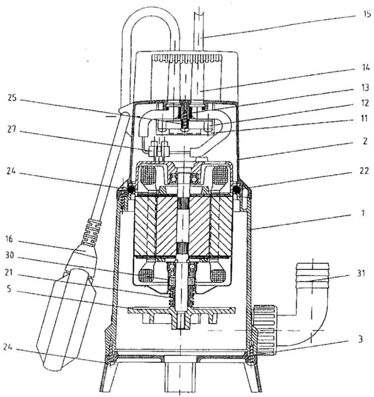
text_image
Technical cross-sectional diagram of a mechanical device with numbered components for identification.ZPK 40 A
| Pos. | Designation | Quantity | Order number |
| 1 | Pump housing 207/00 yellow | 1 | 272091.2 |
| 2 | Motor reception housing 1-hole (without floater) | 1 | 270002.1 |
| 2 | Motor reception housing 2-hole (with floater) | 1 | 270002.2 |
| 3 | Base plate with support bracket | 1 | 272094 |
| 5 | Running wheel d = 105 mm | 1 | 272905.R |
| 11 | Condenser 8 μF | 1 | 279911 |
| 12 | Fixation piece | 1 | 270012 |
| 13 | Plastic sleeve | 2 | 270013 |
| 14 | Bend relief | 2 | 270014 |
| 15 | E-cable with plug L = 10 m | 1 | 270015 |
| 16 | Floating switch L = 0.5 m | 1 | 270016.G |
| 16 A | Compact floating switch (design KS) | 1 | 550.041 |
| 21 | Mechanical seal | 1 | 270021+270921 |
| 22 | O-ring 95x7 | 1 | 270022 |
| 24 | Sheet metal screw 4.2 x 19 | 6 | 270024 |
| 24 | Sheet metal screw 4.2 x 19 for base plate | 4 | 270024 |
| 25 | Sheet metal screw 3.9 x 19 | 3 | 270025 |
| 27 | Terminal block 5-pole | 1 | 270027 |
| 30 | Oil filling 0.01 l | 1 | 117123 |
| 31 | Hose connection piece R 1 1⁄4“ – 1 1⁄4“ | 1 | 129012 |
| 32 | Connecting nut (contained in pos. 34) | 1 | 129910 |
| Motor unit (incl. pos. 5; 21; 30) | 1 | 207047 |
© 2011 by Zehnder GmbH
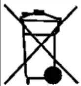
Only for EU countries
Do not put the pump into the household waste!
According to the European Directive 2002/96/EC on Waste Electrical and Electronic Equipment and transposition into national law, wasted electronic tools must be collected separately and must be recycled in an environmentally compatible manner.
Sommaire:
Page
Sommaire 24
- Directive 2006/42/EG relative aux machines
line
| Q(m³/h) | H(m) for ZPK 35 | H(m) for ZPK 40 | H(m) for ZPK 30 | | ------- | --------------- | --------------- | --------------- | | 0 | 11.0 | 10.0 | 8.0 | | 2 | 10.5 | 9.5 | 7.0 | | 4 | 10.0 | 9.0 | 6.0 | | 6 | 9.5 | 8.5 | 5.0 | | 8 | 9.0 | 8.0 | 4.0 | | 10 | 8.5 | 7.5 | 3.0 | | 12 | 8.0 | 7.0 | 2.0 |text_image
Technical cross-sectional diagram of a mechanical device with numbered components for identification.text_image
Technical cross-sectional diagram of a mechanical device with numbered components for identification.ZPK 40 A
© 2011 by Zehnder GmbH