
ZB0074 - Industrial safety device IFM - Free user manual and instructions
Find the device manual for free ZB0074 IFM in PDF.


User questions about ZB0074 IFM
0 question about this device. Answer the ones you know or ask your own.
Ask a new question about this device
Download the instructions for your Industrial safety device in PDF format for free! Find your manual ZB0074 - IFM and take your electronic device back in hand. On this page are published all the documents necessary for the use of your device. ZB0074 by IFM.
USER MANUAL ZB0074 IFM
Original operating instructions
Safety rope emergency stop switches
ZB0050
ZB0051
ZB0070
ZB0071
ZB0074
ZB0075
Contents
1 Preliminary note 3
2 Symbols used 4
3 Warnings.... 5
4 Safety instructions.... 6
5 Intended use.... 7
5.1 Safety-related requirements 7
5.2 IT safety 8
6 Items supplied.... 9
7 Operating and display elements 10
8 Function description 11
9 Installation.... 12
10 Electrical connection.... 15
10.1 Contact arrangement 15
10.2 24 V DC LED 16
10.2.1 Wiring example 16
10.3 110 V AC LED.... 16
10.3.1 Wiring example 17
10.4 Programming example 18
10.5 Data bits 18
11 Technical data.... 19
11.1 Safety characteristics 21
11.2 ATEX characteristics (Ex-approved switch type LS-Ex) 21
12 Approvals / standards 22
13 Scale drawing 23
14 Maintenance, repair and disposal 25
1 Preliminary note
Instructions, technical data, approvals, accessories and further information at www.ifm.com.
2 Symbols used
√ Requirement
Instructions
Reaction, result
[...] Designation of keys, buttons or indications
→ Cross-reference

Important note
Non-compliance may result in malfunction or interference.

Information
Supplementary note
3 Warnings
Warnings indicate the possibility of personal injury and damage to property. This enables safe product handling. Warnings are graded as follows:

WARNING
Warning of serious personal injury
▷ If the warning is not observed, fatal and serious injuries are possible.

CAUTION
Warning of minor to moderate personal injury
▷ If the warning is not observed, minor to moderate injuries are possible.
ATTENTION
Warning of damage to property
▷ If the warning is not observed, damage to property is possible.
4 Safety instructions
- The unit described is a subcomponent for integration into a system.
- The system architect is responsible for the safety of the system.
-
The system architect undertakes to perform a risk assessment and to create documentation in accordance with legal and normative requirements to be provided to the operator and user of the system. This documentation must contain all necessary information and safety instructions for the operator, the user and, if applicable, for any service personnel authorised by the architect of the system.
-
Read this document before setting up the product and keep it during the entire service life.
- The product must be suitable for the corresponding applications and environmental conditions without any restrictions.
- Only use the product for its intended purpose (→ Intended use).
- If the operating instructions or the technical data are not adhered to, personal injury and/or damage to property may occur.
- The manufacturer assumes no liability or warranty for any consequences caused by tampering with the product or incorrect use by the operator.
- Installation, electrical connection, set-up, operation and maintenance of the product must be carried out by qualified personnel authorised by the machine operator.
- Protect units and cables against damage.
- Replace damaged units, otherwise the technical data and safety will be impaired.
- Observe applicable documents.
- Observe the national valid regulations for e-stop devices.
5 Intended use
The safety rope emergency stop switch is used to detect safety-related switching states.
The safety rope emergency stop switch is used
• to secure vast hazardous areas.
• in places where housings or covers are not possible.
Typical application areas:
- conveyors
- rotating machines
- vast hazardous areas
Application area ZB0074
- Adhere to the remarks for safe use in hazardous areas in the enclosed ATEX operating instructions.
5.1 Safety-related requirements
It must be ensured that the safety requirements of the respective application correspond to the requirements stated in these instructions.
Observe the following requirements:
▶ Adhere to the specified operating conditions ( → Technical data).
▶ In case of faults within the device which result in the defined safe state:
Take measures to maintain the safe state when the complete control system continues to be operated.
With appropriate operation, the safety rope emergency stop switch can be used in applications up to performance level e according to ISO 13849-1, depending on the system architecture.
Installation must be in accordance with EN 13850.
If an AS-i network is controlling a machine with potentially dangerous movements and EN 60204-1 applies, a special insulation monitoring device must also be installed.
The device meets the requirements of EN ISO 13850, IEC / EN 60947-5-1 and IEC / EN 60947-5-5.

The wiring influences the achievable control category.
The requirements for external wiring and the selection of the connected switching contacts refer to the functionality to be accomplished and to the required control category (DIN EN ISO 13849-1 or EN 62061).
The control category is either determined by means of a risk analysis (e.g. to DIN EN ISO 12100) or taken from a C standard.
The control category or SIL level of the safe evaluation unit must at least correspond to the control category or SIL level necessary for the application.

Depending on the safety components used the complete safety system can also be classified for a lower control category.
▶ Characteristic safety values of other components, especially of the safe evaluation unit, can be found in the corresponding documentation.
5.2 IT safety
By default, the device is not intended for direct connection to IT systems. If this application is required, the users have to implement it (e.g. by using their own additional components).
6 Items supplied
1 Safety rope emergency stop switch and 1 original operating instructions.
ZB0074:
additionally 1 ATEX operating instructions, 1 original EU declaration of conformity
If one of the above-mentioned components is missing or damaged, please contact one of the ifm branch offices.
7 Operating and display elements
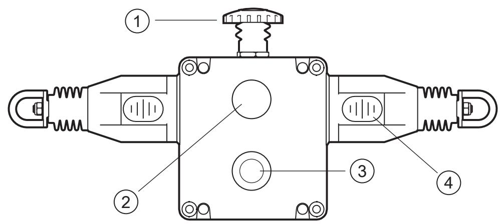
1: E-STOP (red)
3: Dual LED
(ZB0051, ZB0070, ZB0071, ZB0075)
2: Reset button (blue)
4: Rope status indication
Rope status indication

Fig. 1: Indication with properly set steel rope
8 Function description
Pulling the tensioned rope, rope breakage or impact on the E-STOP cause activation of the switching function of the safety rope emergency stop switch.
A window on the device (rope status indication) shows the correct rope tension and facilitates adjustment, troubleshooting and maintenance.
After activation of the E-STOP function a clip mechanism maintains the E-STOP command until it is unlocked manually by pressing the blue reset button.
▶ Before resetting the E-STOP signal the cause of the activation has to be determined.
Reset is only possible with correct rope tension (position indication in middle position).
The max. rope length also depends on the change of the ambient temperature.


Maintenance requirement
Monthly:
Check the proper functioning of the system at various points along the rope length.
Check the setting of the nominal rope tension and retighten the rope if necessary.
Every six months:
Disconnect the device from the voltage supply and remove the cover. Check that the screw terminals are tight and tighten them if necessary.
Check the device for moisture penetration.

▶ Replace damaged or faulty devices. Repair is not permissible.
9 Installation
The device is mounted using four M5 screws. Any installation position is possible.
To ensure protection rating IP67, the following tightening torques must be observed:
- fixing screws 4 Nm
• cover screws (Lid T20 Torx M4) 1.5 Nm
▶ Only use seals of the correct size for the cable entry and the external diameter of the cable.
The maximum vertical pull force on the rope pull is 130 N until activation, the max. travel 300 mm.
▶ Enough space has to be provided so that the required actuation travel can be reached.
▶ Eye bolts have to be installed between the switches across the whole length of the rope at a distance of min. 2.5 m to max. 3 m.
▶ The first eye bolt must be mounted at a distance of max. 500 mm of the switch eye bolt or the tension spring (if it is used).

▷ Do not use the first 500 mm as part of the active protected area (E-STOP triggering).
Installation of components
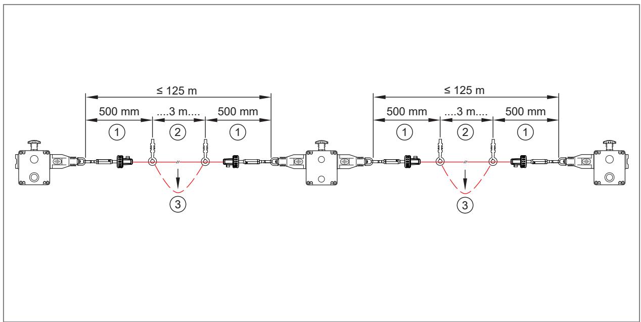
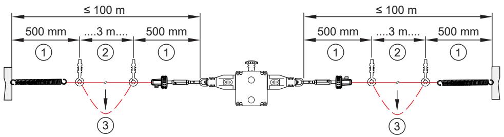
| 1: | Inactive zone 500 mm |
| 2: | Active protected area |
| 3: | Trigger e-stop → pull rope |
 | Eye bolt |
 | Clamping system |
 | Tension spring |
The tension of the rope is obtained by rope tensioner systems.
▶ After installation, set the tension to the middle position.
▷ The tension is indicated by the green arrows in the window of the individual switches.
▶ Check the function of all switches and the control circuits.
▶ To do so, pull on the rope at various points in the active protected area.
▶ Then reset the individual switches by pressing the blue reset button.
▶ Ensure that the switches lock into place.
▶ Reset the switches manually by pressing the blue button.
▶ If necessary, increase the rope tension until the tests along the active length of the area are satisfactory.
The switches are equipped with a red, mushroom-shaped E-STOP button.
▶ Check and reset the individual E-STOP switches to ensure proper operation of the control circuits.
The typical operating conditions for a successful operation of the safety rope emergency stop system are:
• max. 75 N pull force
• and max. 150 mm bending of the rope between the eye bolts for rope support

Rope pull systems with single direction safety rope emergency stop switches are influenced by fluctuations of the ambient temperature.
▷ To ensure proper function of the rope pull system it is mandatory to take into account the dependence on the temperature when fixing the rope length and distance of the eye bolts (every 3 m).

Installation temperature T [°C] ± X [°C] = maximum permissible rope length L [m]
10 Electrical connection

The unit must be connected by a qualified electrician.
▶ Observe the national and international regulations for the installation of electrical equipment.
▶ Wiring is only possible if the device is disconnected from power.
10.1 Contact arrangement
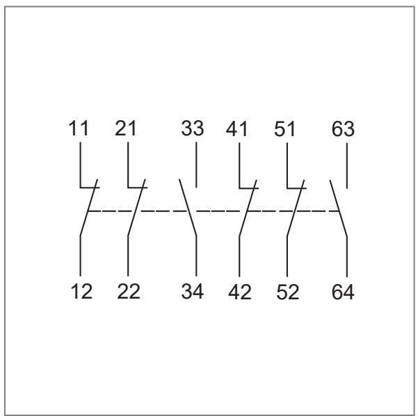
Shifting travels safety rope emergency stop switch
| 0 mm | 4 mm | 15 mm | 17 mm |
| 4 NC + 2 NO | Rope sagging | Tension range | Rope tensioned |
| 11/12 | |||
| 21/22 | |||
| 33/34 | |||
| 41/42 | |||
| 51/52 | |||
| 63/64 | |||
Contact closed | Contact open | ||
10.2 24 V DC LED
ZB0051 / ZB0075
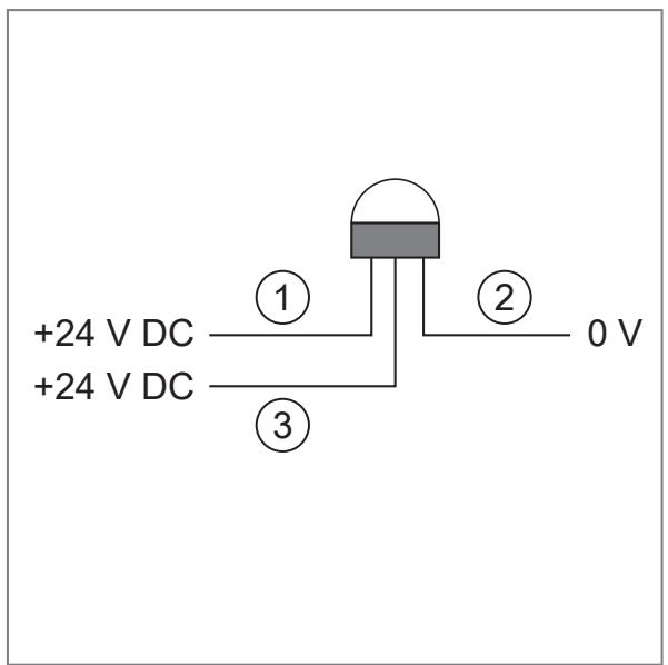
1: +24 V DC at connection 1 → LED red flashes
2:0 V
3: +24 V DC at connection 3 → LED green is on
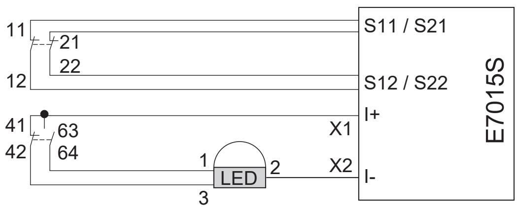
10.2.1 Wiring example
10.3 110 V AC LED
ZB0070 / ZB0071
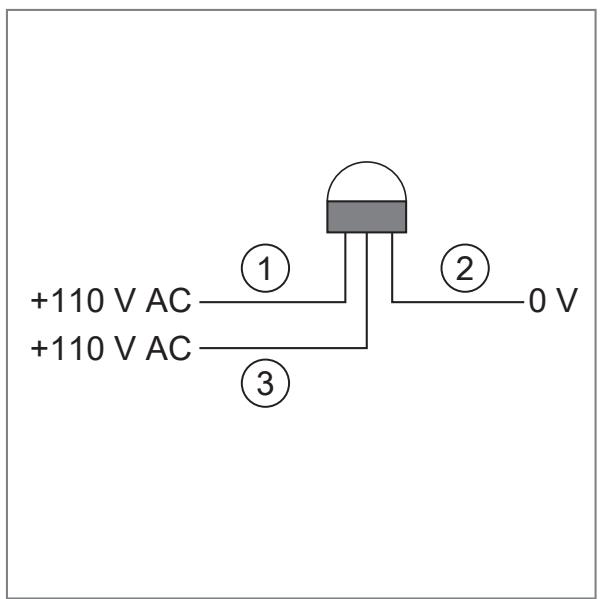
1: 110 V AC at connection 1 → LED red flashes
2: 0 V at connection 2 (black)
3: 110 V AC at connection 3 → LED green is on
10.3.1 Wiring example

1: Safe evaluation unit
10.4 Programming example
| 0001 | 24 V DC / PLC system is in the run mode→ LED output from the safety pcb is active System_is_running——LED |
| 0002 | Rope Switch is triggered→ safety node datas are ZERO from the safety pcb E7015SIN1 ○ AND IN2 ○ IN3 ○ IN4 ○ Rope_pulled |
10.5 Data bits
| Data bit | D3 | D2 | D1 | D0 |
| In / Out | SI-2 | SI-2 | SI-1 | SI-1/O-1 |
| Activated input channel | Bit sequence D3-D0 |
| SI-1 | XX00 |
| SI-2 | 00XX |
| SI-1 and SI-2 | 0000 |
| None | XXXX |
| Activated alarm output | Bit sequence D3-D0 |
| O-1 | XXX1 |
| X = random | |
11 Technical data
| ZB0050 / ZB0051 / ZB0071 | |
| Electrical design | |
| Safety contacts | 4 NC |
| Auxiliary contacts | 2 NO |
| Type of contact | Snap-action contacts |
| Contact material | Silver |
| Switching capacity | AC: 240 V/3 A, 120 V/6 A, inductiveDC: 24 V/2.5 A, inductive |
| Max. switching voltage/switching capacity | 240 V/720 VA |
| Minimum load | 5 V, 5 mA DC |
| Thermal current | 10 A |
| Rated insulation voltage | 500 V |
| Short-circuit / overload protection | External fuse 10 A (FF) |
| Connection | Terminal up to 2.5 mm2 |
| Mechanical design | |
| Fixing elements | 4 x M5 screws |
| Mounting position | any |
| Cable entry | 4 x M20 |
| Max. rope length | 125 m each side |
| Actuating force (rope) | < 125 N |
| Tension force for operating position (axial) | 130 N (between the switches) |
| Switching contacts | to IEC / EN 60947-5-1 |
| Mechanical life | > 1,000,000 activations |
| Function display | |
| Operation | LED green |
| Error | LED red flashing |
| Current rating LED | 15 mA |
| Ambient temperature | -25...80 °C |
| Protection rating | IP 67 |
| Vibration resistance | 10...500 Hz |
| Shock resistance | 15g 11ms |
| Housing material | Die-cast aluminium |
| Housing colour | Yellow |
| ZB0070 / ZB0075 | |
| Electrical design | |
| Safety contacts | 4 NC |
| Auxiliary contacts | 2 NO |
| Type of contact | Snap-action contacts |
| Contact material | Silver |
| Switching capacity | AC: 240 V/3 A, 120 V/6 A, inductiveDC: 24 V/2.5 A, inductive |
| Max. switching voltage/switching capacity | 240 V/720 VA |
| Minimum load | 5 V, 5 mA DC |
| Thermal current | 10 A |
| Rated insulation voltage | 500 V |
| Short-circuit / overload protection | External fuse 10 A (FF) |
| Connection | Terminal up to 2.5 mm2 |
| Mechanical design | |
| Fixing elements | 4 x M5 screws |
| Mounting position | any |
| Cable entry | 4 x M20 |
| Max. rope length | 125 m each side |
| Actuating force (rope) | < 125 N |
| Tension force for operating position (axial) | 130 N (between the switches) |
| Switching contacts | to IEC / EN 60947-5-1 |
| Mechanical life | > 1,000,000 activations |
| Function display | |
| Operation | LED green |
| Error | LED red flashing |
| Current rating LED | 15 mA |
| Ambient temperature | -25...80 °C |
| Protection rating | IP 67 / IP69K |
| Vibration resistance | 10...500 Hz |
| Shock resistance | 15g 11ms |
| Housing material | Stainless steel 316 |
| Housing colour | Silver |
| ZB0074 | |
| Electrical design | |
| Safety contacts | 2 NC |
| Auxiliary contacts | 2 NO |
| Type of contact | Snap-action contacts |
| Contact block explosion-protected | LS-EX |
| Nominal voltage | 250 V AC / DC |
| Nominal current | 8 poles 2.5 A |
| Thermal current | 10 A |
| Rated insulation voltage | 500 V |
| Short-circuit / overload protection | External fuse 10 A (FF) |
| Length connection cable | 3 m |
| Mechanical design | |
| Fixing elements | 4 x M5 screws |
| Mounting position | any |
| Connection | Prewired with a 3 m cable through a stainless steel cable gland |
| Max. rope length | 125 m each side |
| Actuating force (rope) | < 125 N |
| Tension force for operating position (axial) | 130 N (between the switches) |
| Switching contacts | to IEC / EN 60947-5-1 |
| Mechanical life | > 1,000,000 activations |
| Ambient temperature | -20...60 °C |
| Protection rating | IP 67 / gas and dust (zone 21 + 22)IP69K / food |
| Vibration resistance | 10...55 Hz (IEC62-2-6) |
| Shock resistance | 15g 11ms |
| Housing material | Stainless steel 316 |
| Housing colour | Silver |
11.1 Safety characteristics
| Characteristics | Value |
| B10d | 1.5 × 10⁻⁶ cycles at 100 mA load |
| ISO 13849-1 | up to PLe depending on the system architecture |
| EN 62061 | up to SIL3 depending on the system architecture |
| Annual application | 8 cycles per hour/24 hours per day/365 days |
| MTTFd | 214 years |
The safety rope pull switch can be used as part of the safety-related control system to perform the E-STOP function according to EN 13850.
The PFD/PFH values or MTTF d values of the other components (e.g. evaluation units) can be found in the respective documentation.
Explanation of the abbreviations
| PL | Performance level | Capability of safety-related parts to perform a safety function under predictable conditions to fulfil the expected risk reduction. |
| SIL | Safety Integrity Level | Safety Integrity Level SIL 1-4 to EN 62061. The higher the SIL, the lower the probability that a safety function will fail. |
| B10d | Number of cycles at which 10 % of the components have failed and caused danger. | |
| MTTFd | Mean Time To Dangerous Failure | Mean time to dangerous failure. |
11.2 ATEX characteristics (Ex-approved switch type LS-Ex)
The device is fitted with an Ex-approved switch, type LS-Ex, from the company IDEM.
The switch comes with
- an IECEx certificate IECEx BAS11.0133X
- an ATEX type examination certificate Baseefa11ATEX0267X
Marking
• Ex d IIC T6 (-20 °C Ta +60 °C) Gb
• Ex tb IIIC T85 °C (-20 °C Ta +60 °C) Db IP65
12 Approvals / standards
Information on UL 508:
Type 1 housing.
Use copper wires 16 - 12 AWG with a nominal temperature of at least 90 °C.
Use the same polarity for a multiple connection line.
Electrical data:
• 240V AC / 3A (6000 cycles) A300
• 120V / 60A switching element 6A
• Shutdown PF > 0.38 (100,000 cycles)
• 240V / 10A carry only
Wire cross section: 16AWG - 12AWG copper; tightening torque 0.8 Nm (7lb/in).
Operate LED only with LVLC or Class 2.
If necessary, there is a connection terminal for grounding in the housing.
Notes for AS4024.3610 conveyor belts
Information with regard to AS4024.1-2014:
1) Vertical forces to operate the switches midway between the eyebolts → support: check <70N; rope deflection <300 mm
2) Axial forces - directly along the rope axis: <230 N (typically 125 N).
Typical parameters for successful operation of a system is less than 70 N pull force with less than 150 mm deflection of rope between the eyebolt supports.
This can normally be achieved with switches set to the central position between the green arrows in the viewing window.
If required, depending on the necessary checks along the active rope length, the tension can be increased further beyond the central position to ensure a tripping pull force of less than 70N.
13 Scale drawing
ZB0050
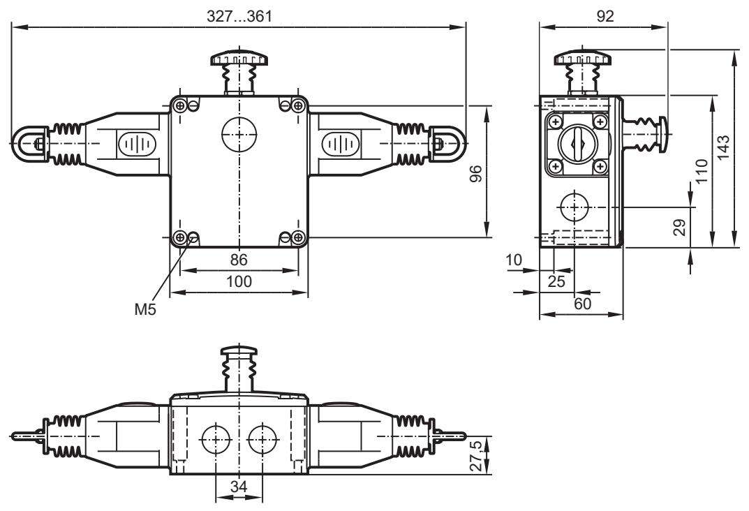
ZB0051 / ZB0070 / ZB0071 / ZB0075
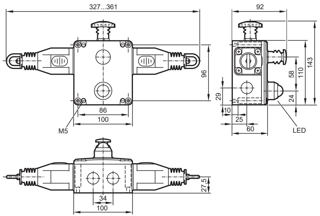
ZB0074

14 Maintenance, repair and disposal
Maintenance requirement for testing the safety function → chapter 8 (functional description).
Only the manufacturer is allowed to repair the unit.

▶ After repair/replacement, carry out a test by requesting the safety function.
▶ After use, dispose of the unit in an environmentally friendly way in accordance with the applicable national regulations.
Cleaning the unit:
▶ Disconnect the unit from the voltage supply.
▶ Clean the unit from dirt using a soft, chemically untreated and dry micro-fibre cloth.
- 1 PRELIMINARY NOTE
- 2 SYMBOLS USED
- 3 WARNINGS
- 4 SAFETY INSTRUCTIONS
- 5 INTENDED USE
- 5.1 SAFETY-RELATED REQUIREMENTS
- 5.2 IT SAFETY
- 6 ITEMS SUPPLIED
- 7 OPERATING AND DISPLAY ELEMENTS
- 8 FUNCTION DESCRIPTION
- 9 INSTALLATION
- 10 ELECTRICAL CONNECTION
- 10.1 CONTACT ARRANGEMENT
- 10.2 24 V DC LED
- 10.2.1 WIRING EXAMPLE
- 10.3 110 V AC LED
- 10.3.1 WIRING EXAMPLE
- 10.4 PROGRAMMING EXAMPLE
- 10.5 DATA BITS
- 11 TECHNICAL DATA
- 11.1 SAFETY CHARACTERISTICS
- 11.2 ATEX CHARACTERISTICS (EX-APPROVED SWITCH TYPE LS-EX)
- 12 APPROVALS / STANDARDS
- 13 SCALE DRAWING
- 14 MAINTENANCE, REPAIR AND DISPOSAL
Brand : IFM
Model : ZB0074
Category : Industrial safety device