
WGen11500TFc - Generator WESTINGHOUSE - Free user manual and instructions
Find the device manual for free WGen11500TFc WESTINGHOUSE in PDF.

User questions about WGen11500TFc WESTINGHOUSE
0 question about this device. Answer the ones you know or ask your own.
Ask a new question about this device
Download the instructions for your Generator in PDF format for free! Find your manual WGen11500TFc - WESTINGHOUSE and take your electronic device back in hand. On this page are published all the documents necessary for the use of your device. WGen11500TFc by WESTINGHOUSE.
USER MANUAL WGen11500TFc WESTINGHOUSE
natural_image
Blue circular icon with a white crown symbol (no text or numbers)User Manual
WGen11500TFc
natural_image
Line drawing of a portable electricity generator with fan and wheels (no text or symbols)DO NOT RETURN THIS PRODUCT TO THE STORE
If you have questions or need assistance, please call customer service at 855-944-3571.
Introduction....2-3
Safety 4-12
Electrical....13
Components 14-15
Assembly 16-17
Operation....18-27
Care and maintenance 27-35
Troubleshooting....36
Accessories 37
Hotline de service/Company Address....Back Page
INTRODUCTION
WARNING
Operating, servicing, and maintaining this equipment can expose you to chemicals including engine exhaust, carbon monoxide, phthalates, and lead, which are known to the State of California to cause cancer and birth defects or other reproductive harm. To minimize exposure, avoid breathing exhaust, and wear gloves or wash your hands frequently when servicing this equipment. For more information go to www.P65warnings.ca.gov.
DISCLAIMERS
All information, illustrations, and specifications in this manual were in effect at the time of publishing. The illustrations used in this manual are intended as representative reference views only. We reserve the right to make any specification or design change without notice.
ALL RIGHTS RESERVED
All rights reserved. No reproduction allowed in any form without written permission from Westinghouse Outdoor Power Equipment.
DANGER
Read this manual be-
fore using or performing maintenance on this product. Failure to follow the instructions and safety precautions in this manual can result in serious injury or death.

UPDATES
The latest User Manual for your Westinghouse products can be found under our support tab. wpowereq.com/pages/manuals
Or scan the following QR code with your smartphone camera to be directed to the link.

PRODUCT REGISTRATION
For trouble-free warranty coverage, it is important to register your Westing-house product.
You can register by:
- Completing and mailing the product registration card included in the carton.
- Registering your product on-line at: wpowereq.com/pages/warranty-registration
- Scanning the above QR code with your smartphone camera to be directed to the mobile registration link.
For Your Records
Date of Purchase: ____
Model Number: ____
Serial Number: ____
Place of Purchase: ____
- Sending the following product information to:
Westinghouse Outdoor Power
Warranty Registration
777 Manor Park Drive
Columbus, OH 43228
IMPORTANT: Keep your purchase receipt for trouble-free warranty coverage.

SPECIFICATIONS
AC Voltage....120V/240V
Power (Running)...11500W (Gasoline), 10500 (Propane), 9500 (Natural Gas)
Power (Peak).....14500W (Gasoline), 13500 (Propane), 12000 (Natural Gas)
AC Current....95.8/47.9A (Gasoline), 87.5/43.75A (Propane), 78.3/39.1A (Natural Gas)
DC Voltage ....5V
DC Current 2x2.1A
Frequency....60 Hz
Phase ...... Single
RPM....3600
Power Factor 1.0
NOTICE
This product is designed and rated for continuous operation at ambient temperatures between 23^ F ( -5^ C) and 104^ F ( 40^ C). If needed, this product can be operated in extremely hot or extremely cold temperatures for short periods. If the product is exposed to extreme temperatures during storage, it should be brought back within the optimal temperature range before operation. This product must always be operated outdoors in a well-ventilated area and far away from doors, windows, and other vents.
Maximum wattage and current are subject to and limited by such factors as fuel BTU content, ambient temperature, altitude, engine conditions, etc. Maximum power decreases about 3.5% for each 1,000 feet above sea level, and will also decrease about 1% for each 10^ F ( 6^ C) above 60^ F ( 16^ C) ambient temperature.
Insulation Class....H
Maximum Ambient Temperature....104°F (40°C)
Fuel Type....Unleaded gasoline (87–93 Octane) Do not use E15 or E85 fuel in this product.
Fuel Capacity....9.5 gallons (36 liters)
Oil Capacity 1.26 quarts (1.2 liters)
Oil Type ....SAE 10W-30
Spark Plug....F7TC
Spark Plug Gap 0.03 in. (0.70 mm)
Valve Intake Clearance....0.0031 - 0.0047 in. (0.08 - 0.12 mm)
Valve Exhaust Clearance ....0.0051 - 0.0067 in. (0.13 - 0.17 mm)
AC Grounding System......Bonded to frame
NOTICE
The effect of altitude on horsepower will be greater if no carburetor modification is made. A decrease in engine horsepower will decrease the power output of the generator. Contact our service team to order altitude kits.
NOTICE
Thank you for choosing Westinghouse! PLEASE READ BEFORE RETURNING THIS PRODUCT FOR ANY REASON.
If you have a question or experience a problem with your Westinghouse purchase, call us at 1-855-944-3571 to speak with an agent.
SAVE THIS MANUAL FOR FUTURE REFERENCE.
HAVE QUESTIONS?
Email us at service@wpowereq.com
or call 1-855-944-3571
SAFETY DEFINITIONS
The words DANGER, WARNING, CAUTION, and NOTICE are used throughout this manual to highlight important information. Make sure that the meanings of this safety information is known to all who operate, perform maintenance on, or are near the generator.

This safety alert symbol appears with most safety statements. It means attention, become alert, your safety is involved! Please read and abide by the message that follows the safety alerts symbol.
DANGER
DANGER Indicates a hazardous situation which, if not avoided, will result in death or serious injury.
WARNING
WARNING Indicates a hazardous situation which, if not avoided, could result in death or serious injury.
CAUTION
CAUTION Indicates a hazardous situation which, if not avoided, could result in minor or moderate injury.
NOTICE
NOTICE Indicates a situation which can cause damage to the generator, personal property, and/or the environment, or cause the equipment to operate improperly.
NOTE: Indicates a procedure, practice or condition that should be followed for the generator to function in the manner intended.
SAFETY SYMBOLS
Follow all safety information contained in this user's manual as well as the information on the product labeling.
| SYMBOL | DESCRIPTION |
 | Safety Alert Symbol |
 | Fire Hazard |
 | Electrical Shock Hazard |
 | Burn Hazard. Do not touch hot surfaces. |
 | Asphyxiation Hazard |
 | Do Not Operate in Wet Conditions |
 | Read Manufacturer's Instructions |
 | Maintain Safe Distance |
 | Ground. Consult with electrician to determine grounding requirements before operation. |
 | Carbon Monoxide |
IMPORTANT SAFETY INSTRUCTIONS
DANGER
Generator exhaust contains high levels of carbon monoxide (CO), an invisible, odorless, and extremely poisonous gas. If you smell exhaust fumes, you are breathing carbon monoxide. But, even if you do not smell exhaust fumes you may be inhaling CO.
ONLY operate generators outside, in a well-ventilated area. NEVER operate generators indoors, doing so CAN KILL YOU IN MINUTES.
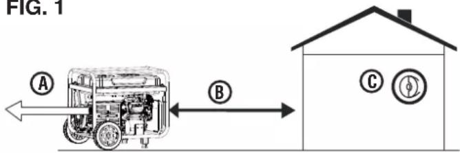
- Correct Use – ONLY use generators outside and downwind, far away from windows, doors and vents. ALWAYS direct exhaust away from occupied spaces. ALWAYS install battery-powered carbon monoxide detectors or plug-in carbon monoxide detectors with battery back-up in living areas. See Figure 1.
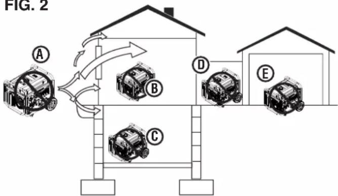
- Incorrect Use – NEVER use a generator in your home, garage, basement, attic, crawl space or any other fully or partially enclosed area. Areas such as these can allow dangerous levels of carbon monoxide to accumulate. An open door or a running fan WILL NOT provide adequate ventilation. See Figure 2.
If you start feeling dizzy, weak, or sick while using the generator, move to fresh air IMMEDIATELY. Contact a doctor. You may be experiencing carbon monoxide poisoning.
DANGER
Fire and electrocution hazard. DO NOT connect to a building's electrical system unless the generator and a transfer switch have been properly installed and the electrical output has been verified by a qualified electrician. The connection must isolate the generator power from utility power and must comply with all applicable laws and electrical codes. Failure to properly isolate the generator power could cause property damage and create a dangerous backfeed of electricity which could kill or seriously injure utility workers.
DANGER
Electrocution hazard. NEVER use the generator in a location that is wet or damp. NEVER expose the generator to rain, snow, water spray, or standing water while in use. Protect the generator from all hazardous weather conditions. Moisture or ice can cause a short circuit or other malfunction in the electrical circuit.
WARNING
Familiarize yourself with all the instructions, safety warnings, illustrations, and specifications provided with this product. Failure to follow the manufacturer's instructions may result in electric shock, fire, and/or carbon monoxide poisoning that can lead to death or serious injury.
FIG. 1
flowchart
graph LR
    A["Device with fan inside"] -->|A| B["House with electrical meter"]
    B -->|B| C["House with electrical meter"]
A - Exhaust (CO)
B - Only use OUTSIDE and FAR AWAY from windows, doors, and vents
C - CO detectors in living areas
FIG. 2
flowchart
graph TD
    A["Position A"] --> B["Position B"]
    B --> C["Position C"]
    C --> D["Position D"]
    D --> E["Position E"]
    style A fill:#f9f,stroke:#333
    style B fill:#f9f,stroke:#333
    style C fill:#f9f,stroke:#333
    style D fill:#f9f,stroke:#333
    style E fill:#f9f,stroke:#333
A - Exhaust (CO)
B - Living area
C - Basement/crawlspace
D - Entryway/porch/mudroom
E - Garage
NOTICE
Install battery-powered carbon monox- s or plug-in carbon monoxide detectors pack-up in living areas.
● This product should ONLY be used outdoors.
- NEVER use a generator in your home, garage, basement, attic, crawl space or any other fully or partially enclosed area. Areas such as these can allow dangerous levels of carbon monoxide to accumulate. Carbon monoxide (CO), an invisible, odorless, and extremely poisonous gas CAN KILL YOU IN MINUTES.
- Only use OUTSIDE and far away from windows, doors, and vents as recommended by the US Department of Health and Human Services Centers for Disease Control and Prevention. Your specific home and/or wind conditions may require additional distance.
- The National Electrical Code requires the use of a transfer switch or other suitable transfer equipment whenever a portable generator is connected to a building's electrical system. Transfer switches isolate generator power from utility power and prevent backfeeding of electric power into the utility system.
NOTE: A transfer switch must be installed by a qualified electrician in accordance with applicable electrical codes. Some jurisdictions may require the installation to be inspected by local authorities. Keep all relevant installation, inspection, and maintenance information.
- Never use the generator to power medical support equipment.
● Never expose the generator to rain, snow, water spray, or standing water while in use. Store and operate the unit in a dry or covered (but not enclosed) location. - Do not let children or untrained individuals operate the generator.
- Keep children, bystanders, and pets a minimum of 10 ft. away from a running generator.
- Maintain Safe Distance. While operating and storing, keep at least five feet of clearance on all sides of the generator, including overhead. Turn the unit off and allow it to cool a minimum of 30 minutes before storage. Heat created by the muffler and exhaust gases could be hot enough to cause serious burns and/or ignite combustible objects.
- Do not operate the unit in areas where combustible or hazardous materials are stored including gasoline and natural gas filling stations.
- Do not operate the generator while barefoot, with wet hands or feet, while standing in water or in wet conditions.
- Do not use this unit when you are tired or under the influence of drugs, alcohol, or medication.
● Burn Hazard. Do not touch hot surfaces. - Do not contact the muffler or engine. They are very HOT and will cause severe burns. Do not put body parts or any flammable or combustible materials in the direct path of the exhaust.
- Keep hands, fingers, feet, and other body parts away from all moving parts of the generator.
- Do not connect worn or damaged electrical cords to the generator. NEVER touch frayed or exposed wires.
- Do not operate the generator on an incline. The unit should always be placed on a flat stable surface.
- Check the physical condition of the product prior to each use. Look for loose bolts, fluid leaks, and other signs of wear. Replace all damaged items. For replacement parts or assistance, contact our customer service team.
- For optimal performance, use the generator in temperatures between 23^ (-5^) and 104^ (40^) with a maximum relative humidity of 90% .
- Before starting the generator, check all fluids (oil and gasoline).
- Do not remove the oil dipstick or fuel cap when the generator is running.
- Securely tighten the oil dipstick after adding oil and the fuel cap after adding gasoline.
-
Avoid skin contact with engine oil or gasoline. Wear protective clothing and equipment. Wash all exposed skin with soap and water. Prolonged skin contact with gasoline or engine oil may cause severe skin irritation and other adverse reactions.
-
Generator's vibrate and bounce during normal operation. Check the generator and all of the cords connected to it for any damage that may have resulted from the vibration. Replace or repair damaged items as needed. Do not use the generator or any items that show signs of damage.
- All electrical tools and appliances operated from this generator must be properly grounded by use of a third wire or be double-insulated.
- Before transporting the generator, disconnect the spark plug boot, drain the fuel tank and properly restrain the unit.
- Fuel or oil may leak from the generator during transport. Place a towel, plastic sheet, or absorbent pad beneath the unit to protect your vehicle.
- To prolong the life of this product, follow the instructions in the Care and Maintenance section of this manual.
- Replace damaged or worn items with recommended or equivalent replacement parts. Using an incorrect or incompatible part might create a hazard that could result in serious personal injury.
- Always remove any tools or other service equipment used during maintenance away from the generator before operating.
GROUNDING
See Figure 3.
WARNING
Shock hazard. Failure to properly or can result in electric shock.
NOTICE
Only use grounded 3-prong extension and appliances, or double-insulated compliances.
The generator neutral is bonded to the frame. There is a permanent conductor between the generator (stator wire) and the frame. If this generator will be used only with cord and plug equipment connected to the receptacles mounted on the generator, National Electric Code does not require that the unit be grounded. However, other methods of using the generator may require grounding to reduce the risk of shock or electrocution.
Before using the ground terminal, consult a qualified electrician, electrical inspector, or local agency having jurisdiction for local codes or ordinances that apply to the intended use of the generator.
DISCONNECTING THE BONDED NEUTRAL
See Figure 3.
The bonded neutral should only be removed under specific circumstances. Consult a qualified electrician to determine if circumstances require disconnecting the bonded neutral.
- Remove the alternator cover.
- Remove the green/yellow bonded jumper wire from the ground bolt and unmarked terminal connection. Reinstall the bolts and tighten securely.
- Keep the bonded jumper wire in a secure location so that the generator can be returned to the original configuration.
NOTICE Apply a new "NEUTRAL UNBONDED" Label over the "NEUTRAL BONDED TO FRAME" label on the front of the control panel.
SAFETY PRECAUTIONS FOR GASOLINE AND GASOLINE VAPOR
DANGER Fire and explosion hazard. Gasoline is highly explosive and flammable and can cause severe burns or death.
WARNING Fire and Burn Hazard. NEVER loosen or remove the fuel cap while the generator is running. Turn the unit off and allow it to cool for at least five minutes before adding gasoline. Loosen the fuel cap slowly.

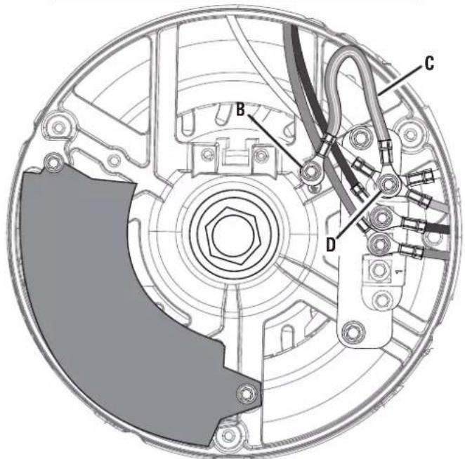
A - Ground terminal
B - Ground bolt
C - Bonded jumper wire (green/yellow)
D - Unmarked terminal connection
WARNING In case of a gasoline fire, do not attempt to extinguish the flame unless the fuel selector switch is in the OFF position. Introducing an extinguisher to a generator with an open fuel valve could create an explosion hazard.
● Fire Hazard. Gasoline is highly flammable. Handle with care.
● Never use gasoline as a cleaning agent.
● Gasoline is a skin irritant and needs to be cleaned up immediately if it comes in contact with the skin.
- Do not store gasoline near furnaces, water heaters, or any other appliances that produce heat or have automatic ignitions.
- Keep gasoline away from sparks, open flames, pilot lights, heat, and other sources of ignition.
- Store any containers containing gasoline in a well-ventilated area, away from any combustibles or source of ignition.
- ALWAYS store gasoline in a container approved for gasoline. Unapproved containers can break or deteriorate allowing gasoline or gasoline vapors to escape which can create a serious hazard.
● Gasoline has a distinctive odor, this will help detect potential leaks quickly.
● Gas vapors can cause a fire if ignited.
- Do not smoke when handling fuel, adding fuel to the generator, or emptying the gas tank.
● Wear eye protection while refueling.
- Before adding fuel to the generator, turn the unit off and allow it to cool a minimum of five minutes. If necessary, move the unit to level ground.
- Do not remove the fuel tank cap when the generator is running.
- Loosen the fuel cap slowly to safely release pressure, keep gasoline from escaping around the cap, and to avoid the heat from the muffler igniting fuel vapors.
- NEVER fill the generator's gasoline tank beyond the maximum fill ring on the fuel screen. Keeping gasoline levels at or below the fill ring will allow for fuel expansion. Overfilling the fuel tank can result in a sudden overflow of gasoline and result in spilled gasoline coming in contact with HOT surfaces.
- Spilled fuel can ignite. Wipe up spills immediately and allow area to dry before operating the generator. NEVER attempt to burn off spilled fuel.
- Securely tighten the fuel cap after adding gasoline.
- Do not cover the fuel cap while the generator is in operation. Covering the cap may cause the engine to fail or damage the product.
- Drain fuel before storing the unit. Store the unit and the fuel separately in well-ventilated areas away from
sparks, open flames, pilot lights, heat, and other sources of ignition.
- Turn the unit off and allow it to cool a minimum of 30 minutes before draining fuel.
LIQUID PETROLEUM GAS (LPG/PROPANE)

WARNING
Fire and explosion hazard. Never use a gas container, LPG/propane hose, propane cylinder or any other fuel item that appears to be damaged. If there is a strong smell of propane while operating the generator, fully close the propane cylinder valve immediately. Once the propane is off, use soapy water to check for leaks on the hose and connections on the tank valve and the generator. Do not smoke or light a cigarette or check for leaks using any open flame source such as a match or lighter. If leak is found, contact a qualified technician to inspect and repair the LPG/propane system before using the generator.

CAUTION
Fire and explosion hazard. Only use approved Propane cylinders with an Overfilling Prevention Device (OPD) valve. Always keep the tank in a vertical position with the valve on top and placed at ground level on a flat surface. Do not allow tanks to be near any heat source. When transporting and storing, turn the propane cylinder valve to the fully closed position and disconnect the tank. Make sure to always cover the generator inlet and tank outlet with protective plastic caps.
● LPG/Propane is highly flammable and explosive.
- In case of a LPG/Propane fire, DO NOT attempt to extinguish the flame if the fuel valve is in the gas position. Introducing an extinguisher to a generator with an open fuel valve could create an explosion hazard.
- LPG/Propane can settle in low places because it is heavier than air.
- LPG/Propane has a distinctive odor added to help detect potential leaks. If there is a smell, DO NOT use the engine.
● Always keep a propane cylinder in an upright position.
- When exchanging propane cylinders, be sure the tank valve is the same type.
- LPG/propane will burn the skin. Prevent skin contact at all times.
- Keep the propane cylinder away from the generator exhaust.
- Large (500–1000 gallon) propane cylinders will require a certified plumber to install the fuel line to the generator and the loose regulator is not used (the regulator that is attached to the fuel tank). The pressure as measured at the regulator mounted to the generator must be 7 in. to 14 in. of water column. A certified plumber must ensure
that the pressure is correct or install a step down regulator if needed.
● Make sure the generator and propane cylinder are on a flat surface before operating.
- If there is a propane odor do not start the unit because there may be a potential leak. Never place a propane cylinder near the engine exhaust.
- When transporting, make sure the propane cylinder and LPG/propane hose are not attached to the generator.
- Store propane cylinder away from sparks, open flames, pilot lights, heat, and other sources of ignition.
- Do not store propane cylinder near furnaces, water heaters, or any other appliances that produce heat or have automatic ignitions.
NATURAL GAS (NG)

WARNING
Fire and explosion hazard. Never supply line, natural gas hose, or that appears to be damaged. If hell of natural gas while operating the off all gas sources immediately. Gas is off, use soapy water to check use and connections on the branch generator. Do not smoke or light a cig-leaks using any open flame source lighter. If a leak is found, contact a inspect and repair the natural gas g the generator.

WARNING
Natural gas (NG) is highly explo- and can cause severe burns or

WARNING
Do not route the natural gas hose ting patio, or other structure. The e.

WARNING
For proper installation, consult a natural gas plumber.

WARNING
Turn off the gas at the natural gas generator is not in use.
NOTICE
Generator installation must strictly com- plicable federal, state, and local laws as s and regulations. Laws and regulations the installation of this equipment are rou- ed and may vary based on relevant local now the generator will be used, and the site. Check with the authority having local (AHJ) for a complete list of laws, regula- des that may apply to you. Information in should never be interpreted in a way that in any local, state, or federal laws. When in s abide by local laws.
- Inspect natural gas hose before each use and replace if damaged.
- Only use natural gas hoses that comply with local, state, or federal laws. Hose requirements may vary in different regions. Check with the authority having local jurisdiction (AHJ).
- Verify that the natural gas supply line from the house was properly installed by a qualified plumber and that the natural gas hose is securely connected before using the generator.
- Before starting the engine, purge the natural gas supply line and perform a leak test.
● Always disconnect the generator and natural gas hose from the natural gas supply line when the gas supply is being pressure tested. - Keep the natural gas hose and natural gas supply line away from the muffler and other heated surfaces.
- Keep a fire extinguisher near the generator at all times.
LEAK TESTING
See Figure 4.
NOTICE
Connections on the hose and the natural gas/propane inlet were tested at the factory to make sure there were no gas leaks. However, shipping and handling may have loosened connections. We recommend that you always test for leaks before using the generator.
To test for natural gas (NG) leaks:
- Connect the natural gas hose to the natural gas/propane inlet on the generator and to the natural gas supply line.
- Brush the inlet, hose connections, and gas supply valve with a soapy solution made of a 20/80 mixture of mild soap and water.
-
If bubbles begin growing, there is a leak.
-
If the leak is at the inlet, contact customer service. DO NOT USE THE GENERATOR.
- If the leak is at the hose connections, reinstall the hose securely and perform the check again. If the leaks persist, DO NOT USE THE GENERATOR.
- If the leak is at the natural gas supply line, DO NOT USE THE GENERATOR.
To test for LPG/Propane leaks:
- Connect the LPG/propane hose to the natural gas/propane inlet on the generator and to the cylinder valve.
- Open the cylinder valve. If you hear a rushing sound, immediately turn off the cylinder valve. This noise indicates a significant leak at the connection. Replace the cylinder or have it repaired.
- Brush the inlet, hose connections, and LP gas cylinder with a soapy solution made of a 20/80 mixture of mild soap and water.
- If bubbles begin growing, there is a leak.
- If the leak is at the inlet, contact customer service. DO NOT USE THE GENERATOR.
- If the leak is at the hose connections, reinstall the hose securely and perform the check again. If the leaks persist, DO NOT USE THE GENERATOR.
- If the leak is at the cylinder, do not use or move the cylinder. Contact the fire department or the gas supplier.
FIG. 4
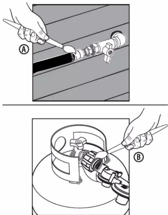
A - Leak testing with soapy water (natural gas)
B - Leak testing with soapy water (propane)
IMPORTANT INFORMATION FOR THE CO SENSOR
The CO Sensor monitors for the accumulation of poisonous carbon monoxide gas around the generator when the engine is running. If increasing levels of CO gas are detected, the CO Sensor automatically shuts down the engine.
The CO Sensor will also detect the accumulation of carbon monoxide from other fuel burning sources used in the area of operation. For example, if the exhaust of fuel burning tools is pointed at a CO Sensor-equipped generator, a shut-off may be initiated due to rising CO levels. This is not an error. Hazardous carbon monoxide has been detected. Move and redirect any additional fuel burning sources to dissipate carbon monoxide away from personnel and occupied buildings.
NOTE: Remote start-equipped generators must be restarted with the START/STOP button on the control panel after an automatic shut-down occurs.
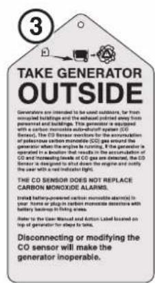
Generators are intended to be used outdoors, far from occupied buildings and the exhaust pointed away from personnel and buildings. If misused and operated in a location that results in the accumulation of CO, like in a partially enclosed area, the CO Sensor shuts off the engine and the RED indicator light will flash notifying the user that there are unsafe levels of carbon monoxide.
If the generator shuts off and the RED indicator light flashes, leave the area immediately. Wait for the carbon monoxide to dissipate and the RED indicator light to turn off before returning to the affected area. Once it is safe to return, read the Action Label for further steps to take. The CO Sensor DOES NOT replace carbon monoxide alarms. Install battery-powered carbon monoxide alarm(s) in your home.
WARNING
Automatic shutoff accompanied with a flashing RED light in the CO Sensor portion of the control panel is an indication that the generator was improperly located which allowed carbon monoxide to accumulate to unsafe levels. If you start to feel sick, dizzy, weak, or carbon monoxide detectors in your home indicate an alarm, get to fresh air immediately. Call emergency services. You may have carbon monoxide poisoning.
UNDERSTANDING THE CO SENSOR'S INDICATOR LIGHTS
See Figure 5.
| COLOR DESCRIPTION | |
RED | Unsafe levels of carbon monoxide accumulated around the generator. After shut-off, the RED indicator light in the CO Sensor area of the control panel will flash to provide notification that the generator was shut-off due to carbon monoxide levels rising above a safe threshold. The RED light will flash for at least five minutes after a CO shut-off.When it is safe to do so, move the generator to an open, outdoor area far away from occupied spaces with exhaust pointed away. Once relocated to a safe area and the red light is off, the generator can be restarted. Introduce fresh air and ventilate the area where the generator had shut down. |
YELLOW | A CO sensor system fault occurred. When a system fault occurs, the generator is automatically shut down and the YELLOW indicator light in the CO auto-shutoff area of the control panel will flash to provide notification that a fault has occurred. The YELLOW light will flash for at least five minutes after a fault. The generator can be restarted but may continue to shutoff. A CO sensor fault can only be diagnosed and repaired by an authorized Westinghouse service center. |
A - Service generator LED
B - Automatic shutoff LED
SAFETY LABELS AND DECALS
The following information is on your generator's labels and decals.
① Action Label
If unsafe levels of carbon monoxide accumulate around the generator, automatic shutoff will occur. If the unit shuts off, leave the area immediately. When it is safe to return, do the following:
- Move the generator to an open, outdoor area.
- Point exhaust away.
- Don't run generator in enclosed areas (e.g. not in house or garage).
- Move to fresh air.
- Get medical help if sick, dizzy or weak.
- WARNING – Tampering with carbon monoxide sensor could result in hazardous condition.
② Carbon Monoxide
- Using a generator indoors CAN KILL YOU IN MINUTES. Generator exhaust contains carbon monoxide. This is a poison you cannot see or smell.
- NEVER use inside a home or a garage, EVEN IF doors and windows are open.
③ Take Generator Outside
Generators are intended to be used outdoors.
④ California Proposition 65
Cancer and reproductive harm – www.P65Warnings.ca.gov/product
⑤ Pinch Point Hazard
Keep fingers and hands away from pinch point.
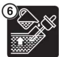
⑥ Adding Oil
Add engine oil until the oil level is within safe operating range.
⑦ Specifications
(See page 3)
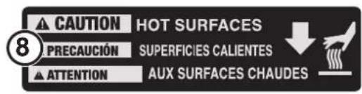
⑧ Hot Surface
Do not touch.
⑨ Choke On/Off
The generator has a two position choke.
10 Performance Label
(See page 3)


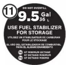
⑪ Fuel Capacity
This generator has a 9.5 gallon fuel tank. ALWAYS use CLEAN, FRESH, unleaded gasoline (87–93 octane) in this unit. Do not use E15 or E85 fuel in this product.
⑫ Engine Displacement
This unit has a 550 cc engine.
⑬ Danger Label
Read User Manual before operating generator. Gasoline, Natural Gas, and LPG/Propane is highly flammable. Leaking gasoline, natural gas or LPG can cause a fire or explosion if ignited. If you smell gasoline, natural gas, or propane while operating the unit, immediately shut OFF the fuel and/or propane valve. Keep gasoline container, natural gas hoses, and propane cylinder away from exhaust.
⑭ No Oil
Oil has been drained from the unit for shipping. Add oil before attempting to operate the unit.
⑮ Caution Label
Turn off propane and natural gas when the generator is off or when the generator is using gas.
⑯ Maintain Air Cleaner
Clean air filter every 50 hours (every 10 hours if operating in dusty conditions).
⑰ Fuel Valve
Turn the fuel valve to the on position when starting the unit. Turn the fuel valve to the off position when the unit is not in use.
⑱ Customer Service
For technical assistance or service call toll free at 1-855-944-9571
⑲ EZ Start Instructions
Refer to the "EZ Start Instructions" label and the instructions in the Operations section when starting and stopping the generator.
20 Safety Symbols
(See page 4)


DANGER
Read User Manual before operating generator. Gasoline and LPG/Propane is highly flammable. Leaking gasoline or LPG can cause a fire or explosion if ignited. If you smell gasoline or propane while operating the unit, immediately shut OFF the fuel and/or propane valve. Keep gasoline container and propane tank away from exhaust.
PELIGRO
GENERATOR CAPACITY
NOTICE
Do not overload the generator's capacity. Exceeding the generator's wattage/amperage capacity can damage the generator and/or electrical devices connected to it.
Review the Specifications for this generator and record the running (continuous) and peak (starting) watts. In general the higher the wattage, the more devices can be powered at the same time. The total power requirements of all connected devices must be considered. Power requirements are often listed on a device's data label or nameplate.
To determine power requirements:
- Choose the devices you want to power simultaneously.
- Record and total the running (continuous) watts of each device. The generator must continuously produce this amount of wattage to keep the devices running.
- Record the peak (starting) watts for each device. This is the momentary surge of power required to start electric motors in some tools and appliances.
- Select the device with the highest peak (starting) wattage. Add the peak (starting) watts for that device to the total running (continuous) watts for all the connected devices to determine the total peak wattage requirement for the generator.
NOTE: Total peak wattage requirement assumes intermittent starting of devices. Adjust estimate if devices reach peak wattage at the same time.
MANAGING GENERATOR POWER
To extend the service life of the generator, use caution when adding electrical loads. Disconnect all loads before starting the generator. The safest way to manage generator power is to add loads sequentially by doing the following:
- Remove all loads and start the generator as described later in this manual.
- Connect and start the largest device or appliance. Power requirements are often listed on a device's data label or nameplate.
- Allow the generator output to stabilize. Once stable, the engine should run smoothly and the device should function properly.
- Connect and start the next largest device or appliance.
- Allow the generator output to stabilize.
- Repeat this process for each additional load.
EXTENSION CORDS
!
WARNING
Asphyxiation hazard. Extension cords running directly into the home increase the risk of carbon monoxide poisoning through any openings. If an extension cord running directly into your home is used to power indoor items, there is a risk of carbon monoxide poisoning to people inside the home. Always use battery-powered carbon monoxide detector(s) that meet current UL 2034 safety standards when running the generator. Regularly check the detector(s) battery.
!
WARNING
Asphyxiation hazard. When operating the generator with extension cords, make sure the generator is located in an open, outdoor area far away from occupied spaces with exhaust pointed away.
!
WARNING
Fire and electrocution hazard. Never use worn or damaged extension cords. Damaged or overloaded extension cords could overheat, arc, and burn resulting in death or serious injury.
Before connecting an AC appliance or power cord to the generator:
- Use grounded 3-prong extension cords, tools, and appliances, or double-insulated tools and appliances.
● Make sure the tool or appliance is in good working order. Faulty appliances or power cords can create a potential for electric shock.
● Make sure the electrical rating of the tool or appliance does not exceed the rated power of the generator or the receptacle being used.
NO
ICE Do not exceed the unit's capacity. Overloading the generator's wattage and/or amperage capacity could damage connected devices and critical generator components.
EXTENSION CORD SIZING
Make sure your extension cord can carry the required load. Cables that are too small may cause a voltage drop that can cause the cord to overheat or cause property damage. Refer to the cord manufacturer's guidelines for the appropriate size and length.
UNDERSTANDING YOUR GENERATOR
See Figures 6 - 7.
To reduce the risk of injury and product failure, read and understand the information in this user's manual as well as the information on the product labeling.
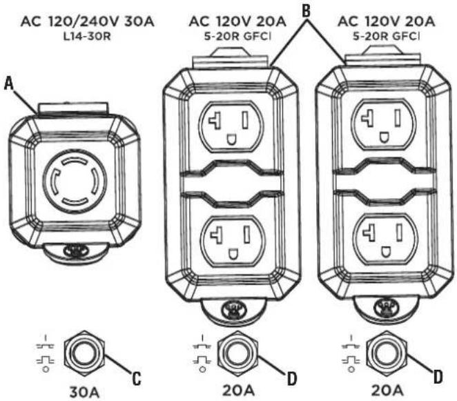
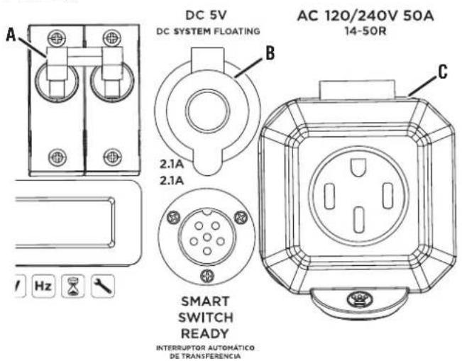
120 VOLT AC, 20 AMP RECEPTACLES
This unit has two single phase, 60 Hz receptacles capable of carrying a maximum of 20 amps.
120/240-VOLT AC RECEPTACLES (50 AMP)
This receptacle can supply either 120V or 240V up to 50 amps.
BATTERY CHARGING PORT
Use the battery charging port along with the included battery charger to charge the battery.
BATTERY INDICATOR
Indicates that battery power is available. Light will remain illuminated while the battery has charge.
BATTERY SWITCH
Enables or disables electric start. The battery switch must be in the ON positoin to use remote start.
CIRCUIT BREAKERS
(20 AMP AND 30 AMP)
The circuit breakers protect individual circuits from electrical overload.
NOTE: The 20 amp circuit breaker limits the current that can be delivered through the 5–20R GFCI receptacles to 20 amps and the 30 amp circuit breaker limits the current for the L14-30R receptacle to 30 amps.
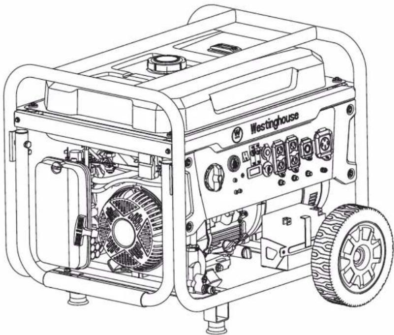
FIG. 6
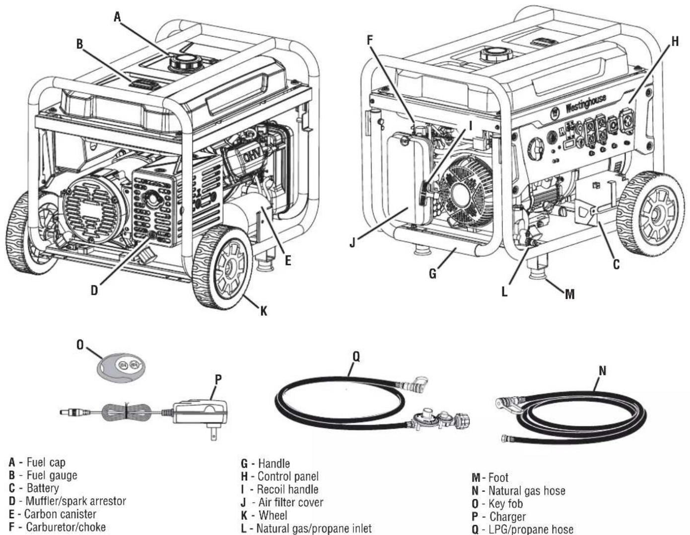
A - Fuel cap
B - Fuel gauge
C - Battery
D - Muffler/spark arrestor
E - Carbon canister
F - Carburetor/choke
G - Handle
H - Control panel
I - Recoil handle
J - Air filter cover
K - Wheel
L - Natural gas/propane inlet
M - Foot
N - Natural gas hose
0 - Key fob
P - Charger
Q - LPG/propane hose
CO SENSOR INDICATOR LIGHTS
The CO Sensor monitors for the accumulation of poisonous carbon monoxide gas. If increasing levels of CO gas are detected, the CO Sensor automatically shuts down the engine.
DATA CENTER
Displays voltage, frequency, total hour meter, and run/maintenance timer.
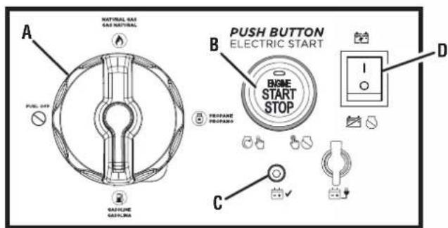
ENGINE START/STOP BUTTON
Push once to automatically start the engine. Push again to stop the engine.
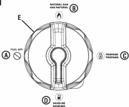
FUEL SELECTOR SWITCH
Use the fuel selector switch to choose a gasoline, propane, or natural gas fuel source.
FUEL TANK
The generator has a fuel tank with a capacity of 9.5 gallons.
NOTE: The fuel gauge on top of the tank shows the approximate fuel level.
GROUND TERMINALS
The ground terminals are used to externally ground the generator.
MAIN CIRCUIT BREAKER
The main circuit breaker controls total output of all outlets to protect the generator from overload or short circuit.
MUFFLER AND SPARK ARRESTOR
The spark arrestor prevents sparks from exiting the muffler. It must be removed for servicing.
NOTICE
The spark arrestor is a safety device that
prevents sparks from exiting the muffler and creating a fire hazard. In certain locations a spark arrestor may be required by law. It is the operator's responsibility to know and follow all local laws and regulations related to fire prevention requirements.
OIL DIPSTICK
Unscrew the oil dipstick to check oil levels and add oil when needed.
RECOIL HANDLE
Use the recoil handle (along with the fuel valve and choke) to manually start the generator.
REMOTE START
Use the key fob to start the generator remotely.
SMART SWITCH OUTLET
The smart switch outlet allows you to connect a Westinghouse ST Switch (sold separately) to the generator.
USB PORTS
Two-port 5V/2.1A USB outlet. Accepts Type A USB plugs.
FIG. 7
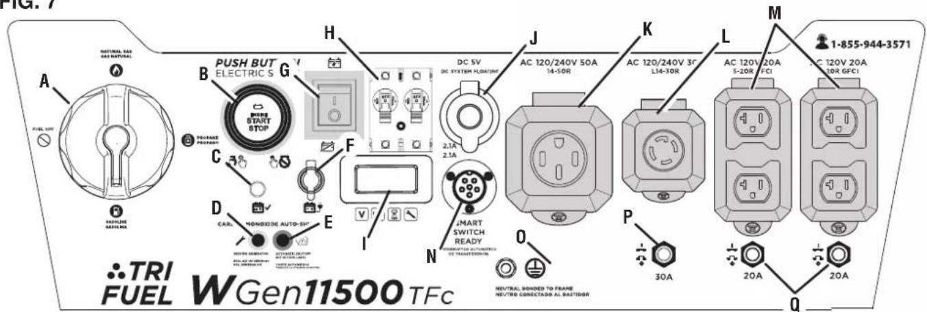
A - Fuel selector switch
B - Engine start/stop button
C - Battery indicator
D - Service generator LED
E - Automatic shutoff LED
F - Battery charging port
G - Battery switch
H - Main circuit breaker
I - Data center
J - USB ports
K - 120/240 volt AC 50 amp receptacle
L - 120/240 volt AC 30 amp receptacle
M - 120 volt AC 20 amp GFCI receptacles
N - Smart switch outlet
0 - Ground terminal
P - 30 amp circuit breaker
Q - 20 amp circuit breakers
WARNING
Weight hazard. Always have assistance when lifting the generator. Never attempt to lift the unit by the handle. Hold the unit by the frame and use proper lifting techniques to reduce the risk of back injury.
REMOVING CARTON CONTENTS
WARNING
This product requires assembly. Do not attempt to operate this product if any items in the INCLUDED LIST are already assembled when you remove the carton contents. These items are not assembled by the manufacturer and should require customer assembly. Using an improperly assembled product can be hazardous and could result in serious personal injury.
- Carefully cut down the sides of the packaging and remove the carton contents.
- Inspect the carton contents. Verify that all the items in the INCLUDED LIST are present and undamaged.
● Recycle or dispose of the packaging materials properly.
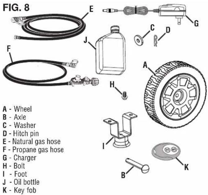
INCLUDED LIST
See Figure 8.
Generator, Wheels, Axles, Washers, Hitch Pins, Bolts, Feet, Key Fob, Charger, Propane Gas Hose, Natural Gas Hose, Engine Oil (SAE 10W 30), Funnel, Spark Plug Socket Wrench, Quick Start Guide, User Manual
If any parts are missing, contact our service team at service@wpowereq.com or call 1-855-944-3571.
INSTALLING THE FEET
See Figure 9.
- Place the generator on a flat surface.
- Lift the handle side of the generator high enough to gain access to the crossbar on the bottom of the frame.
- Place props beneath the generator to serve as a temporary support.
- Locate the feet and bolts.
- Align the holes in a foot with the nuts in the crossbar.
- Insert bolts through the holes in the foot and nuts in the cross bar.
● Tighten bolts securely. Do not over tighten. - Repeat these steps to install second foot.
INSTALLING THE WHEELS
See Figure 10.
- Place the generator on a flat surface.
- Lift the muffler side of the generator high enough to gain access to the bottom of the frame.
- Place props beneath the generator to serve as a temporary support.
- Locate the axles, wheels, washers, and hitch pins.
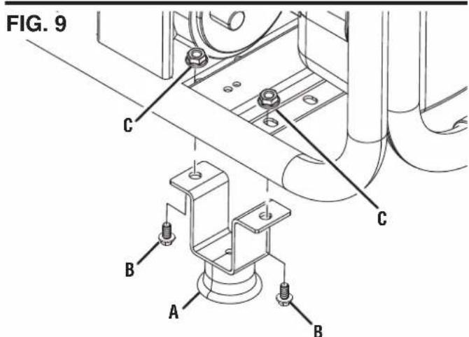
A - Foot
B - Bolt
C - Nut
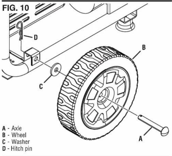
- Insert an axle through the middle of a wheel, washer, and the frame as shown.
- Push a hitch pin into the axle until the center of the pin rests against the top of the axle.
- Repeat these steps to install second wheel.
CONNECTING THE BATTERY
See Figure 11.
A quick-connect battery cable is pre-installed on the battery. Remove the cable tie securing the plugs then push firmly to connect them.
NOTE: The generator is equipped with a battery charging feature. Once the engine is running, a small charge will slowly recharge the battery.
RAISING/LOWERING THE HANDLE
See Figure 12.
- Stand in front of the unit, grasp the handle firmly and lift it to the raised position.
- With the handle in the raised position, the generator can safely be rolled from one position to another. For information regarding transporting the unit in a vehicle, refer to the Transporting section in Operation.
● To lower the handle, gently guide the handle to the down position.
CAUTION
Pinch point hazard. Do not place your hand or fingers between the handle and the generator's frame.
WARNING
Do not alter or modify this product unless instructed to so in this manual or by the manufacturer. Do not use attachments or accessories that are not recommended for use with this product. Making unauthorized modifications and using incompatible accessories can damage the unit and void your warranty.
OVERVIEW
This portable generator can provide power to a wide range of items including household appliances, job-site tools, camping equipment, tailgating essentials, and much more.
NOTICE
THIS GENERATOR HAS BEEN SHIPPED WITHOUT OIL. Do not attempt to crank or start engine before it has been properly serviced with recommended oil. Failure to add engine oil before starting will result in serious engine damage that is not covered under warranty.

A - Quick-connect battery cable
FIG. 12
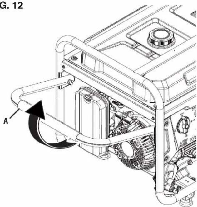
A - Handle
DANGER
Generator exhaust contains high levels of carbon monoxide (CO), an invisible, odorless, and extremely poisonous gas. If you smell exhaust fumes, you are breathing carbon monoxide. But, even if you do not smell exhaust fumes you may be inhaling CO.
ONLY operate generators outside, in a well-ventilated area. NEVER operate generators indoors, doing so CAN KILL YOU IN MINUTES.
- Correct Use – ONLY use generators outside and downwind, far away from windows, doors and vents. ALWAYS direct exhaust away from occupied spaces. ALWAYS install battery-powered carbon monoxide detectors or plug-in carbon monoxide detectors with battery back-up in living areas. See Figure 1.
- Incorrect Use – NEVER use a generator in your home, garage, basement, attic, crawl space or any other fully or partially enclosed area. Areas such as these can allow dangerous levels of carbon monoxide to accumulate. An open door or a running fan WILL NOT provide adequate ventilation. See
Figure 2.
If you start feeling dizzy, weak, or sick while using the generator, move to fresh air IMMEDIATELY. Contact a doctor. You may be experiencing carbon monoxide poisoning.
WARNING
Do not alter or modify this product unless instructed to so in this manual or by the manufacturer. Do not use attachments or accessories that are not recommended for use with this product. Making unauthorized modifications and using incompatible accessories can damage the unit and may void your warranty.
NOTICE
In certain circumstances, the National Electric Code may require the generator to be grounded to an approved earth. Consult with a qualified electrician to determine grounding requirements before operation.
WARNING
Avoid skin contact with engine oil or gasoline. Wear protective clothing and equipment. Wash all exposed skin with soap and water. Prolonged skin contact with gasoline or engine oil may cause severe skin irritation and other adverse reactions.
NOTICE
Check the physical condition of the product prior to each use. Look for loose bolts, fluid leaks, and other signs of wear. Replace all damaged items.
NOTICE
Make sure the wheels and feet are properly installed before adding fuel or oil.
KNOW HOW TO SAFELY LOCATE AND OPERATE YOUR GENERATOR
DANGER
Asphyxiation hazard. Place the generator in a well-ventilated area. DO NOT place the generator near vents or intakes where exhaust fumes could be drawn into occupied or confined spaces. Carefully consider wind and air currents when positioning the generator.
WARNING
Electrocution hazard. Never use the generator in a location that is wet or damp. Never expose the generator to rain, snow, water spray, or standing water while in use. Protect the generator from all hazardous weather conditions. Moisture or ice can cause a short circuit or other malfunction in the electrical circuit. Using a generator or electrical appliance in wet conditions, such as rain or snow, or near a pool or sprinkler system, or when your hands are wet, could result in electrocution.
WARNING
Fire hazard. Only operate the generator on a solid, level surface. Operating the generator on a surface with loose material such as sand or grass clippings can cause debris to be ingested by the generator that could block cooling vents or the air intake system. Allow the generator to cool for 30 minutes before transport or storage.
- Read and understand all safety information before starting the generator (see pages 4–12).
- NEVER use a generator in your home, garage, basement, attic, crawl space or any other fully or partially enclosed area. Areas such as these can allow dangerous levels of carbon monoxide to accumulate. Carbon monoxide (CO), an invisible, odorless, and extremely poisonous gas CAN KILL YOU IN MINUTES.
- DO NOT operate the generator in the back of a SUV, camper, trailer, truck bed (regular, flat, or otherwise), under stairs, next to walls or buildings, or in any other location that will not allow for adequate cooling of the generator and/or the muffler. Operating the generator in enclosed or partially enclosed areas will allow dangerous levels of CO to accumulate.
- DO NOT contain generators during operation.
- Only use OUTSIDE and far away from windows, doors, and vents as recommended by the US Department of Health and Human Services Centers for Disease Control and Prevention. Your specific home and/or wind conditions may require additional distance.
- Do not operate the generator on an incline. The unit should always be placed on a flat stable surface.
- The generator should be on a flat, level surface at all times (even while not in operation).
● The generator must have at least 5 ft. (1.5 m) of clearance from all combustible material.
KNOW THE REGULATIONS FOR THE USE OF PORTABLE GENERATORS
Consider where and how you intend to use your generator, and familiarize yourself with any local, state, or federal ordinances concerning your intended use. It may be necessary to contact a qualified electrician or local governing agency for a full list of requirements.
ADDING OIL/CHECKING OIL LEVEL
See Figure 13.
If your product has a separate engine manual, disregard the information in this section and follow the instructions in the engine manual.
NOTICE
THIS GENERATOR HAS BEEN
SHIPPED WITHOUT OIL. Do not attempt to crank or start engine before it has been properly serviced with recommended oil. Failure to add engine oil before starting will result in serious engine damage that is not covered under warranty.
NOTICE
Use of 2-stroke/cycle oil or other unapproved oil types can cause severe engine damage that is not covered under warranty.
The included, recommended oil type for typical use is 10W-30 engine oil. If running the generator in extreme temperatures, refer to the following chart.
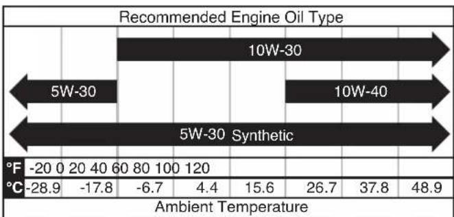
bar
Recommended Engine Oil Type | Oil Type | 5W-30 | 10W-30 | 5W-30 Synthetic | | :--- | :--- | :--- | :--- | | Ambient Temperature | -28.9 | -17.8 | -6.7 | | Ambient Temperature | 4.4 | 15.6 | 26.7 | | Ambient Temperature | 37.8 | 48.9 | |NOTE: Check the engine oil level before each use or every 8 hours of operation.
- Turn the generator off and allow the engine to cool for at least five minutes.
- Place the generator on a level surface in a well-ventilated area.
- Clean the area around the oil dipstick.
For initial oil fill:
- Slowly unscrew and remove the oil dipstick.
- Using the funnel, slowly pour the supplied engine oil into the oil fill hole. Stop frequently to make sure you do not overfill.
NOTE: Your generator was functionally tested in the factory and may contain minimum residual oil. Additional oil is required to operate the unit. Do not overfill.
- Replace and tighten the oil dipstick.
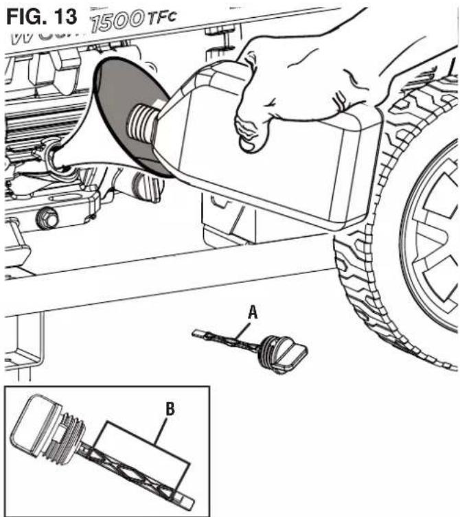
A - Oil dipstick
B - Safe operating range
To check oil level:
- Slowly unscrew and remove the oil dipstick.
- Clean the dipstick and re-seat it inside the oil fill hole. Do not thread the dipstick.
- Remove the dipstick and verify that the oil level is within safe operating range.
- If the oil level is low, add recommended engine oil incrementally and recheck until the level is within the safe operating range.
- Replace the oil dipstick and hand-tighten.
GASOLINE REQUIREMENTS
NOTICE
Do not use E15
or E85 fuel in this product. Engine or equipment damage caused by stale fuel or the use of unapproved fuels (such as E15 or E85 ethanol blends) is not covered by warranty. Only use unleaded gasoline containing up to 10% ethanol.

- ALWAYS use CLEAN, FRESH, unleaded gasoline (87–93 octane) in this unit. NEVER use OLD, STALE, or CONTAMINATED gasoline.
- Up to 10% ethanol (gasohol) is acceptable (where available; non-ethanol fuel is recommended).
- DO NOT use E85 or E15.
- DO NOT use a gas oil mix.
● DO NOT modify the engine to run on alternate fuels.
USING FUEL STABILIZER
Adding a fuel stabilizer (not included) extends the usable life of fuel and helps prevent deposits from forming that can clog the fuel system. Follow the manufacturer's instructions for use.
Always mix the correct amount of fuel stabilizer to gasoline in an approved gasoline container before fueling the generator. Run the generator for five minutes to allow the stabilizer to treat the entire fuel system.
ADDING GASOLINE
See Figures 14 - 15.
DANGER Fire and explosion hazard. Never remove the fuel cap or refuel the generator while the engine is running. Do not smoke or create sparks while fueling. Always turn the engine off and allow the generator to cool for at least five minutes before refueling.
DANGER Fire and explosion hazard. Do not overfill fuel tank. Fill only to the red maximum fill ring on the fuel screen. Overfilling may cause fuel to spill onto engine causing a fire or explosion hazard.
WARNING Never use a gasoline container, gasoline tank, or any other fuel item that is broken, cut, torn or damaged.
NOTICE Only fill the tank from an approved gasoline container. Make sure the gasoline container is internally clean and in good condition to prevent fuel system contamination.
- Turn the generator off and allow the engine to cool for at least five minutes.
- Place the generator on a level surface in a well-ventilated area. DO NOT fuel indoors.
● Clean area around fuel cap and remove the cap slowly. - Slowly add the recommended fuel. Do not overfill.
NOTE: The gasoline level should NOT be higher than the red maximum fill ring on the fuel screen.
NOTE: The fuel gauge on top of the tank shows the approximate fuel level.
● Install the fuel cap. Tighten securely.
- Clean up any spilled fuel.
- Move at least 30 ft. away from refueling area before restarting the engine.
FIG. 14
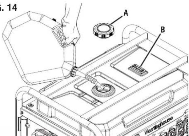
A - Fuel cap B - Fuel gauge
FIG. 15
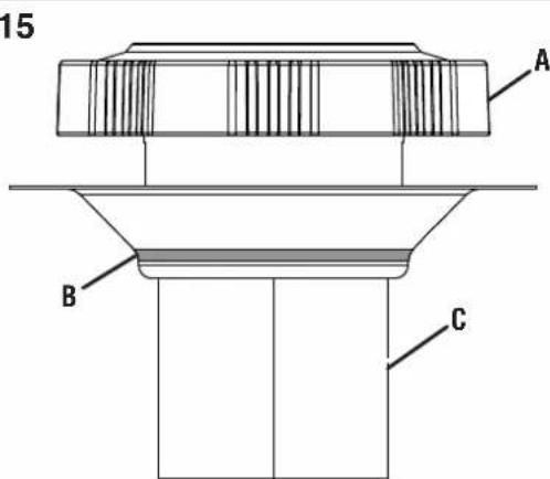
A - Fuel cap
B - Max fill line
C - Screen filter
NOTICE Fuel can damage paint and plastic. Use caution when filling the fuel tank. Damage caused by spilled fuel is not covered under warranty.
NOTICE Clean the fuel screen filter of debris before and after each fueling. Remove the fuel screen filter by slightly compressing it while removing it from the fuel tank.
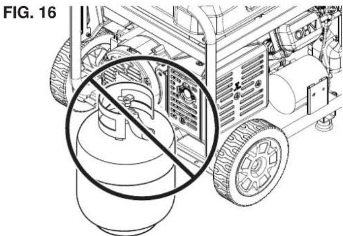
LP GAS CYLINDER REQUIREMENTS
NOTICE Propane cylinders that use liquid withdrawal system can not be used on these models.
LP gas is extremely flammable and could ignite spontaneously when mixed with air. The LP gas cylinder used with this generator must meet the following requirements:
- The cylinder must be manufactured and labeled in accordance with the Specifications for LP Gas Cylinders of the U.S. Department of Transportation (D.O.T.) or the National Standard of Canada, CAN/CSA-B339, Cylinders, Spheres, and Tubes for Transportation of Dangerous Goods; and Commission.
● The cylinder must have a safety relief valve.
- The cylinder must include a UL listed Overfill Protection Device (OPD). Cylinders with this safety feature will have a unique triangular handwheel. Only use LP gas cylinders with this type of handwheel.

● The cylinder must be periodically certified for use by the authority having local jurisdiction (AHJ). Before use, verify that the certification date on the cylinder has not expired.
- All new cylinders must be purged of air and moisture prior to filling. Used cylinders that have not been plugged or kept closed must also be purged. The purging process should be done by a propane supplier (Cylinders from an exchange supplier should have been purged and filled properly).
CONNECTING AN LP GAS CYLINDER TO THE GENERATOR
See Figures 16 - 18.
DANGER Fire and explosion hazard. Never connect or disconnect the LPG/propane hose while the engine is running. Do not smoke or create sparks while handling LPG/propane. Always turn the engine off and allow the generator to cool for at least five minutes before connecting the propane cylinder.
WARNING Never use a gas container, LPG/propane hose, propane cylinder or any other fuel item that appears to be damaged.
WARNING To reduce the risk of injury, perform a leak test any time the LP gas cylinder is disconnected and reconnected.
- Turn the generator off and allow the engine to cool for at least five minutes.
- Place the generator on a level surface in a well-ventilated area. DO NOT connect or disconnect the LP gas cylinder indoors.
- Place the LP gas cylinder near the generator, but do not place it in the path of the muffler exhaust.
NOTE: The propane cylinder can be of any capacity but it must conform to the LP Gas Cylinder Requirements listed earlier in this section.
- Verify that the handwheel is in its full off position.
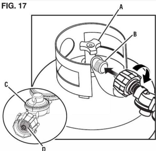
A - Handwheel
B - Cylinder valve
C - LPG/propane hose
D - Nipple
- Hold the LPG/propane hose firmly and push the nipple into the cylinder valve.
- Use your hand to thread the LPG/propane hose to the cylinder valve. Do not cross-thread. Do not use tools or sealants.
NOTE: You will feel some resistance as the hose seals in the cylinder valve. To complete the connection, turn the connector an additional one-half to three-quarters of a turn. If you are unable to complete the connection, disconnect the hose and try again. If you still cannot complete the connection, DO NOT use this hose!
- Connect the LPG/propane hose to the generator using the quick-connect collar.
• Pull back the quick-connect collar.
- Push the hose onto the natural gas/propane inlet.
- Push the collar forward so that the hose is secured properly. Gently pull the hose to see that it is secure.
CONNECTING GENERATOR TO NATURAL GAS SUPPLY LINE
See Figures 18 - 19.
DANGER
Fire and explosion hazard. Never connect or disconnect the natural gas hose while the engine is running. Do not smoke or create sparks while handling natural gas. Always turn the engine off and allow the generator to cool for at least five minutes before connecting to natural gas.
WARNING
Never use a natural gas supply line, natural gas hose, or any other fuel item that appears to be damaged.
WARNING
To reduce the risk of injury, perform a leak test any time the natural gas hose is disconnected and reconnected.
● Turn the generator off and allow the engine to cool for at least five minutes.
- Verify that the gas is turned off at the natural gas supply line.
- Completely unwrap and straighten the natural gas hose to prevent kinks.
- Use your hand to thread the hose to the natural gas supply line. Do not cross-thread. Do not use tools or sealants.
- Connect the natural gas hose to the generator using the quick-connect collar.
• Pull back the quick-connect collar.
- Push the hose onto the natural gas/propane inlet.
- Push the collar forward so that the hose is secured properly. Gently pull the hose to see that it is secure.
SELECTING THE FUEL SOURCE
See Figure 20 - 21.
DANGER
Fire and explosion hazard. DO NOT add gasoline to the fuel tank or connect the LPG/propane hose or natural gas hose to the generator while the generator is in operation.
FIG. 18
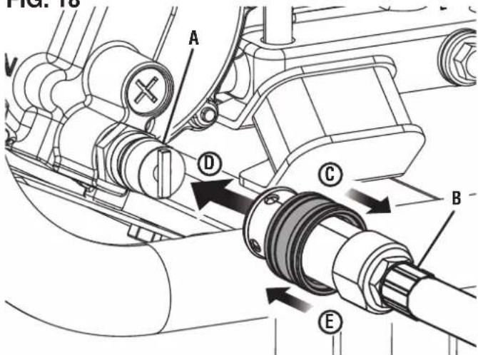
A - Natural gas/propane inlet
B - Natural gas hose or LPG/propane hose
C - Pull collar back
D - Push hose onto inlet
E - Push collar forward
FIG. 19
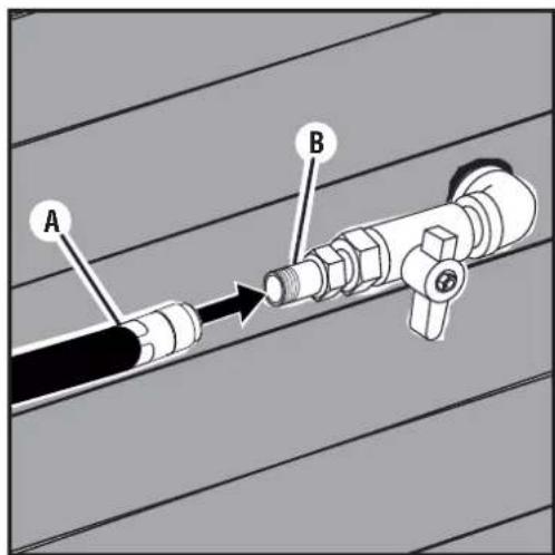
A - Natural gas hose
B - Natural gas supply line
NOTICE
Do not overload the generator. Load carrier depending on the fuel source. Before fuel sources, make sure the generator can high running (continuous) and peak (start- or the items your connected items.
NOTICE
Do not overload the generator. Load car or depending on the fuel source. Before fuel sources, make sure the generator can weigh running (continuous) and peak (start- or the items your connected items.
The fuel source can be switched while the engine is off or while it is running if a propane tank or natural gas supply line is connected to the generator BEFORE operation. If you switch from gasoline to another fuel source while the engine is running, it may run rough for a few seconds as it purges gasoline from the carburetor.
To switch to gasoline:
- Turn the fuel valve to the open position to start the flow of gasoline.
- Rotate the fuel selector switch to Gasoline
● Turn off the flow of natural or propane gas.
To switch to propane:
- Open the cylinder valve on the LP gas cylinder to start the flow of propane.
- Rotate the fuel selector switch to Propane
● Turn off the flow of natural gas and gasoline.
To switch to natural gas:
- Open the valve on the natural gas supply line to start the flow of natural gas.
- Rotate the fuel selector switch to Natural Gas
● Turn off the flow of propane and gasoline.
Engine power is reduced the higher you operate above sea level. Output will be reduced approximately 3.5% for every 1000 feet of increased altitude from sea level.
High altitude adjustment is required for operation at altitudes over 5,000 ft. (1524 m). Operation without this adjustment will cause decreased performance, increased fuel consumption, and increased emissions.
NOTICE
DO NOT operate the generator at alti-2,000 ft. (762 m) with the high altitude kit gine damage may occur.
| High AltitudeCarburetor Kit | Part# 518563 |
DATA CENTER
See Figure 22.
Push the mode button to cycle through the data display modes.
Voltage: Displays current voltage output.
Frequency (Hz): Displays power output frequency in Hertz.
Lifetime Hours: Displays the lifetime run hours.
FIG. 20
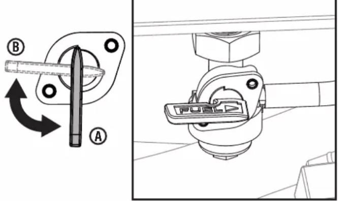
A - Fuel valve (open)
B - Fuel valve (close)
FIG. 21
E - Fuel selector switch
Run Time/Maintenance: Displays current run time. Resets to zero when shut down. Maintenance reminder displayed when required.
Maintenance Codes:
P25 – Change engine oil
P50 – Clean air filter, Change engine oil
P100 – Change engine oil, clean air filter, replace fuel filter
PAIRING THE KEY FOB
See Figures 23 - 24.
● Bring the key fob in range of the generator.
- Ensure the battery is connected and the fuel selector switch is in the FUEL OFF position ⊙
- Push the battery switch to the ON position.
NOTE: When battery power is available, the battery indicator light will illuminate and the LED around the engine start/stop button will illuminate solid green.
- Press and hold the engine start/stop button for 10 seconds until the LED around the button flashes green, then release it.
-
Press and hold the start button on the key fob for one second, then release it.
-
If the key fob paired successfully, the LED around the engine start/stop button will turn solid green.
- If pairing was unsuccessful, the LED around the engine start/stop button will continue flashing green. Wait several seconds, then make a second attempt. If the second attempt fails, turn the battery switch to the OFF position, wait several seconds and repeat the process. If subsequent attempts fail, turn the battery switch to the OFF position and contact customer service.
● After the key fob is successfully paired to the generator, turn the battery switch to the OFF position.
BREAK-IN PERIOD
For proper break-in, do not exceed 50% of the rated running watts during the first five hours of operation.
Use supplied oil until first recommend oil change. Do not use full synthetic oil during break in period. Full synthetic oil may prevent proper breaking and seating of the piston rings.
Vary the load occasionally to allow stator windings to heat and cool and help seat the piston rings.
BEFORE STARTING THE GENERATOR
Verify that:
● The generator is placed in a safe, appropriate location.
● The generator is on a dry, flat, and level surface.
● Oil and fuel levels are within safe operating range.
- All loads are disconnected from the control panel receptacles.
FIG. 22
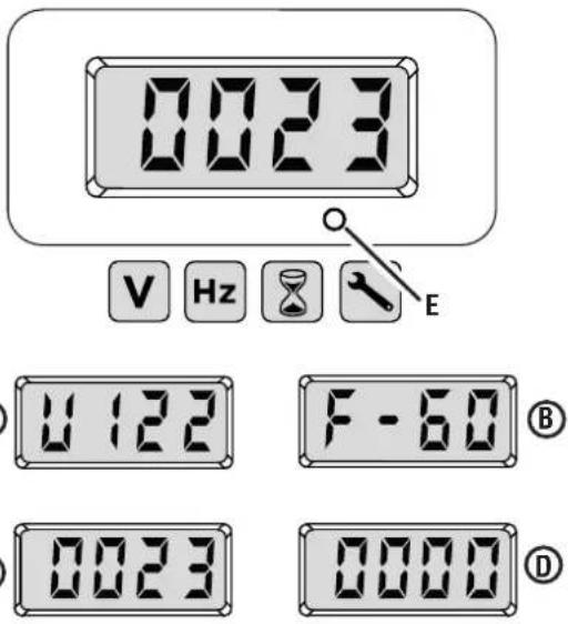
A - Voltage
B - Frequency
C - Lifetime hours
D - Run time/maintenance reminder
E - Mode button
FIG. 23
A - Red LED
B - Start button
C - Stop button
D - Key fob
FIG. 24
A - Fuel selector switch
B - Engine start/stop button
C - Battery indicator
D - Battery switch

Fire and explosion hazard. DO
NOT move or tip the generator during operation.
STARTING THE GENERATOR
See Figures 24 - 27.
- Place the generator in a safe, appropriate location.
- Unplug all loads.
- Check oil and fuel levels. If needed add oil, refill the LP gas cylinder, add gasoline, or contact your natural gas utility company.
- Using the fuel selector switch, select GASOLINE PROpane or NATURAL GAS
-
Start the flow of your desired fuel and stop the flow from other fuel sources.
-
For gasoline, open the fuel valve and turn off the flow of natural or propane gas.
- For propane, open the cylinder valve on the LP gas cylinder and turn off the flow of natural gas and gasoline.
- For natural gas, open the valve on the natural gas supply line and turn off the flow of propane gas and gasoline.
● Push the battery switch to the ON position.
NOTE: When battery power is available, the battery indicator light and the green LED around the engine start/stop button will illuminate.
To start the generator using the recoil handle:
- Move the choke to the on/cold start position.
NOTE: If the engine is warm, move the choke towards the on/warm start position (about 2/3 of the way).
- Firmly grasp and pull the recoil handle slowly until you feel increased resistance. At this point, pull the recoil handle rapidly away from the generator until the engine starts.
NOTE: Gently return the recoil handle into place after starting the unit. Do not let it snap back against the unit. During initial starting, additional pulls may be required to prime the fuel pump.
● After the engine starts, move the choke to the off/warm start position.
To start the generator using the remote start feature:
- Push and hold the start button on the key fob for two seconds.
NOTE: The red LED on the key fob should blink each time the start button is pressed. If the red LED does not blink and the generator does not start, then the battery in the fob may need to be replaced. If the red LED does blink but the generator does not start, the generator's battery may need to charge. Start the unit using the recoil handle. The generator's battery will charge as the unit runs.
FIG. 25
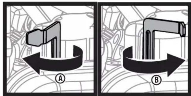
A - Choke (on/warm start)
B - Choke (off/cold start)
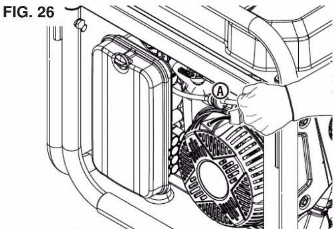
natural_image
Technical line drawing of a mechanical assembly with a hand operating a component labeled 'A', no visible text or symbols.A - Recoil handle
FIG. 27
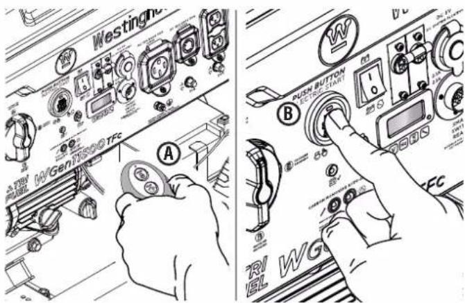
A - Key fob
B - Engine start/stop button
To start the generator using the engine start/stop button:
- Push and hold the engine START/STOP button for two seconds.
NOTE: If the engine START/STOP button does not start the generator, the generator's battery may need to charge.
Start the unit using the recoil handle. The generator's battery will charge as the unit runs.
To add loads after starting the generator:
- When the generator output stabilizes, you can safely connect loads to the control panel receptacles.
NOTE: Verify that all devices are turned off before connecting them to the generator.
NOTE: Make sure that the wattage requirements for all connected devices are in line with your generator's capabilities.
- Connect and start the largest device or appliance.
- Allow the generator output to stabilize. Once stable, the engine should run smoothly, and the device should function properly.
- Connect and start the next largest device or appliance.
- Allow the generator output to stabilize.
- Repeat this process for each additional load.
STOPPING THE GENERATOR
See Figures 24 and 27.
- Remove any connected loads from the control panel receptacles.
- Allow the generator to run at "no load" to reduce and stabilize engine and alternator temperatures.
- Press and hold the engine START/STOP button or the stop button on the key fob for one second to stop the generator.
- Turn the battery switch off.
- Turn the fuel selector switch to the FUEL OFF position
-
Stop the flow of fuel.
-
For gasoline, close the fuel valve.
- For propane, close the cylinder valve on the LP gas cylinder.
- For natural gas, close the valve on the natural gas supply line.
- Disconnect the propane hose from the LP gas cylinder and the generator or disconnect the natural gas hose from the natural gas supply line and the generator.
To stop the unit quickly in an emergency:
- Press and hold the engine START/STOP button or the stop button on the key fob for one second to stop the generator.
CIRCUIT BREAKERS
See Figures 28 - 29.
The 20 amp circuit breaker protects devices and equipment connected to the 120V, 20 amp receptacles from electrical overload. The 30 amp circuit breaker protects devices and equipment connected to the 120V, 30 amp receptacles. The main circuit breaker will automatically switch OFF if the combined load of the receptacles exceeds the generator's capacity. If a circuit breaker activates, turn off the
FIG. 28
A - 120/240 volt AC 30 amp receptacle
B - 120 volt AC 20 amp GFCI receptacles
C - 30 amp circuit breaker
D - 20 amp circuit breakers
FIG. 29
A - Main circuit breaker
B - USB ports
C - 120/240 volt AC 50 amp receptacle
connected device, remove it from the port or outlet, and reset the circuit breaker.
USB PORTS
See Figure 29.
Use the USB ports and USB cables (not included) to charge USB-compatible devices such as phones, tablets, and speakers (up to 2.1 Amps).
NOTE: The USB ports are designed for charging only and do not have data transfer or communication capabilities.
TRANSPORTING
- Turn off the generator.
- Allow the generator to cool a minimum of 30 minutes before transporting.
- Replace all protective covers on the generator control panel.
- Always use the generator's frame, not the handle, to lift the unit or attach any load restraints such as ropes or tie-down straps. DO NOT attempt to lift or secure the generator by holding onto any of its other components.
- Keep the unit level during transport to minimize the possibility of fuel leakage or, if possible, drain the fuel or run the engine until the fuel tank is empty before transport.
CAUTION
CAUTION Fire hazard. DO NOT up-end the generator or place it on its side. Fuel or oil can leak and damage to the generator may occur.
CARE AND MAINTENANCE
WARNING Accidental start-up. Disconnect the spark plug boot (see figure 33) from the spark plug when performing maintenance on the generator.
WARNING Replace damaged or worn items with recommended or equivalent replacement parts. Using an incorrect or incompatible part might create a hazard that could result in serious personal injury.
WARNING Allow hot components to cool for 30 minutes before performing any maintenance procedure.
WARNING Avoid skin contact with engine oil or gasoline. Wear protective clothing and equipment. Wash all exposed skin with soap and water. Prolonged skin contact with gasoline or engine oil may cause severe skin irritation and other adverse reactions.
NOTICE Check the physical condition of the product prior to each use. Look for loose bolts, fluid leaks, and other signs of wear. Replace all damaged items. For replacement parts or assistance, contact our customer service team.
To prolong the life of this product, follow the care and maintenance instructions in this section. Contact customer service before servicing any recall or warranty parts.
CLEANING THE GENERATOR
Do not store or operate your generator in dirty, dusty, or corrosive environments. Do not allow foreign materials and debris to clog the vents on the unit.
NEVER clean the generator with a garden hose. Water can damage the generator's fuel system and electrical components. If the unit needs to be cleaned, use a soft brush and damp cloth to clean the exterior and use low pressure air (no greater than 25 psi) to clean the vents.
Never use gasoline as a cleaning agent.
CLEANING/REPLACING THE AIR FILTER See Figure 30.
Keep air filter clean. A dirty air filter can cause poor performance and decrease the service life of the product. NEVER operate the generator without an air filter in place.
● Turn the generator off and allow the engine to cool for 30 minutes.
- Rotate the knob counterclockwise and remove the cover.
- Remove the air filter from the air cleaner housing and place it in a suitable cleaning container. Replace the air filter if damaged.
NOTE: The air filter may be covered in oil. Use an appropriate container.
- Wash the air filter by submerging the filter in a solution of household detergent soap and warm water. Slowly squeeze the filter to thoroughly clean.
NOTICE
DO NOT twist or tear the air filter during cleaning or drying. Only apply slow but firm squeezing action.
- Rinse the air filter by submerging it in fresh water and applying a slow squeezing action. Allow the filter to dry thoroughly.
NOTICE
Do not pollute. Follow the guidelines of the EPA or other governmental agencies for proper disposal of hazardous materials. Consult local authorities or reclamation facility.
- Dip the air filter in clean engine oil then squeeze out all excess oil. The engine will smoke when started if too much oil is left in the filter.
● Install the air filter in the air cleaner housing and reinstall the air filter cover.
CHANGING THE ENGINE OIL
See Figures 31 - 32.
For optimal performance, change the engine oil according to the figures specified in the maintenance schedule or the engine manual (if applicable). When using the generator under extreme, dirty, dusty conditions or in extremely hot weather, change the oil more frequently.
NOTE: Change the oil while the engine is warm but not hot. Warm engine oil drains more quickly and thoroughly than cool lubricant. Contact with hot lubricant will cause serious burns.
- Turn the generator off and allow the engine to cool for 30 minutes.
- Place the generator on a level surface in a well-ventilated area.
To change the engine oil:
● Clean the area around the oil dipstick.
- Slowly unscrew and remove the oil dipstick.
FIG. 30
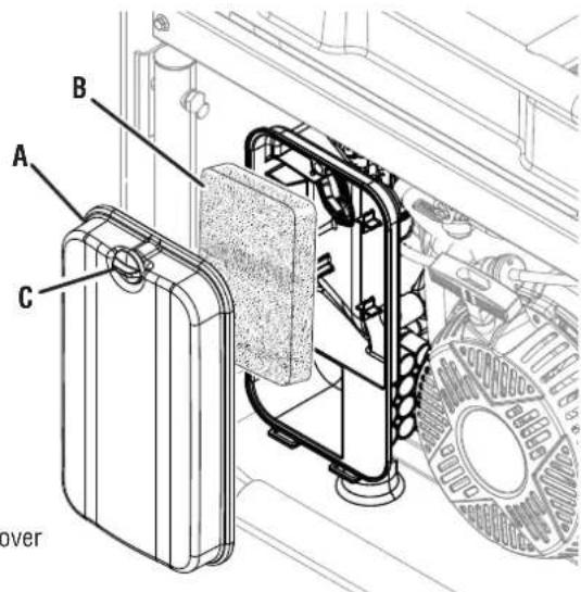
A - Air filter cover
B - Air filter
C - Knob
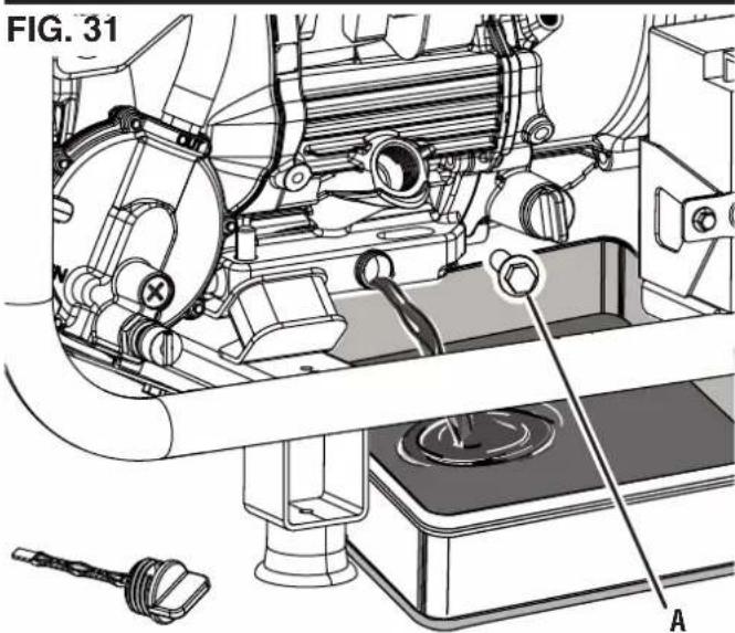
A - Oil drain bolt
- Place an oil pan (or suitable container) under the oil drain bolt.
- Remove the oil drain bolt and allow the oil to drain.
● After the oil has drained completely, replace the oil drain bolt.
● Refill the oil as described in the Operations section. - Replace the oil dipstick and hand-tighten.
- Clean up any spilled oil.
To clean the oil filter:
- Clean the area around the oil filter.
- Slowly unscrew and remove the oil filter.
- Wash the oil filter with warm soapy water, then rinse and dry.
- Replace the oil filter and hand-tighten.
- Clean up any spilled oil.
CLEANING/REPLACING THE SPARK PLUG
See Figure 33.
NOTICE
ALWAYS use the Westinghouse OEM or compatible non-resistor-type spark plug. Use of resistor-type spark plug can result in rough idling, misfire, or may prevent the engine from starting.
Make sure the spark is clean and properly gapped. To clean or replace your spark plug:
- Turn the generator off and allow the engine to cool for 30 minutes.
- Place the generator on a level surface in a well-ventilated area.
- Remove the spark plug boot by firmly pulling the spark boot directly away from the engine.
- Clean the area around the spark plug.
- Remove the spark plug with the included spark plug socket wrench.
NOTICE
Never apply any side load or move the spark plug laterally when removing the spark plug.
- Inspect the spark plug. Replace if electrodes are pitted, burned, or the insulator is cracked. Only use a recommended replacement plug.
● Measure the spark plug electrode gap with a wire-type feeler gauge. If necessary, correct the gap by carefully bending the side electrode.
Spark plug gap: 0.024 - 0.032 in. (0.60 - 0.80 mm)
- Carefully install the spark plug finger tight, then tighten as additional 3/8 to 1/2 turn with the spark plug wrench.
● Install the spark plug boot.
FIG. 32
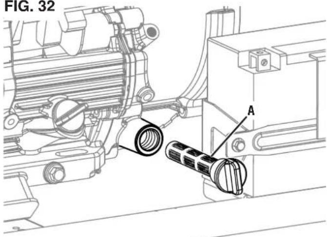
A - Oil filter
FIG. 33
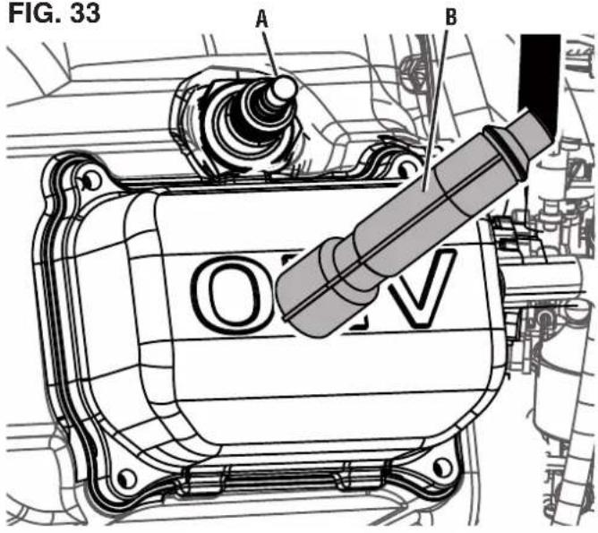
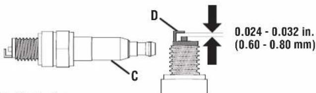
A - Spark plug
B - Spark plug boot
C - Insulator
D - Electrode
CLEANING THE SPARK ARRESTOR
See Figure 34.
Check and clean the spark arrestor according to the figures specified in the maintenance schedule or the engine manual (if applicable). Failure to clean the spark arrestor will result in degraded engine performance.
- Turn the generator off and allow the engine to cool for 30 minutes.
- Place the generator on a level surface in a well-ventilated area.
- Remove the two screws securing the spark arrestor bracket.
- Remove the bracket, screen, and spark arrestor from the generator.
● Gently clean the screen and spark arrestor using a wire brush.
● Reinstall the spark arrestor, screen, and bracket. Tighten screws securely.
DRAINING THE FUEL TANK AND CARBURETOR FLOAT BOWL
See Figures 35 - 36.
WARNING
ALWAYS store gasoline in a container approved for gasoline. Unapproved containers can break or deteriorate allowing gasoline or gasoline vapors to escape which can create a serious hazard.
Even properly stabilized fuel can leave residue and cause corrosion if left long term. If storing the generator for two to six months, drain the float bowl to prevent gum and varnish buildup in the carburetor. If storing the generator for longer than six months, drain the fuel tank to prevent fuel separation, deterioration, and deposits in the fuel system.
- Turn the generator off and allow the engine to cool for 30 minutes.
- Place the generator on a level surface in a well-ventilated area.
- Disconnect the propane hose from the LP gas cylinder and the generator or disconnect the natural gas hose from the natural gas supply line and the generator.
To drain the float bowl:
- Turn the fuel selector switch to the FUEL OFF position and close the fuel valve.
- Place a drain hose (not included) on the bottom of the carburetor float bowl as shown.
- Place the bottom end of the drain hose (not included) into an approved gasoline container to catch the drained fuel.
- Loosen the float bowl drain screw and allow the fuel to drain. Tighten the float bowl drain screw.
- Remove the drain hose (not included).
FIG. 34
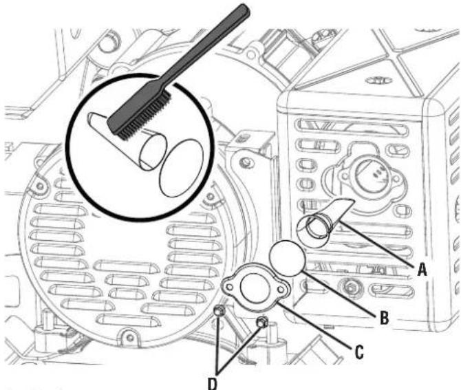
A - Spark arrestor
B - Screen
C - Bracket
D - Screws
FIG. 35
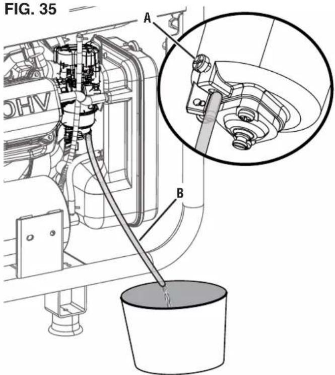
A - Drain screw
B - Drain hose (not included)
To run the float bowl dry:
- Turn the fuel selector switch to Gasoline Band start the generator as described earlier.
● After the engine starts, close the fuel valve. - Allow the generator to run until the fuel in the carburetor is depleted and the engine stops.
To drain the fuel tank:
NOTICE
To prevent damage to the unit, drain the before emptying the fuel tank. See Chang-line oil for details.
- Turn the fuel selector switch to the FUEL OFF position ⊙ and open the fuel valve.
- Clean area around fuel cap and remove the cap slowly.
- Remove the fuel screen filter by slightly compressing it while removing it from the tank.
- Using a commercially available gasoline hand pump (not included), siphon the gasoline from the fuel tank into an approved gasoline container. DO NOT use an electric pump.
NOTE: The fuel tank can also be drained using the carburetor drain screw and drain hose as described earlier. Turn the fuel selector switch to Gasoline and open the fuel valve to allow fuel to flow from the tank through the carburetor.
REPLACING THE FUEL VALVE
See Figure 37.
Overtime, the fuel filter inside the fuel valve may become dirty or clogged. To reduce the risk of engine failure, replace the entire fuel valve including the filter according to the figures specified in the maintenance schedule or the engine manual (if applicable).
● Turn the generator off and allow the engine to cool for 30 minutes.
- Drain the fuel tank as described previously.
- Locate the fuel valve and note the valve's orientation.
NOTE: Place an approved gasoline container beneath the fuel valve to catch any remaining fuel.
- Using pliers, squeeze the fuel line clip and slide the fuel line away from the filter.
● Using a 19 mm wrench (not included), loosen and remove the fuel valve from the tank.
- Thread the new fuel valve onto the fuel tank and tighten securely.
● Install the fuel line onto the new fuel valve.
FIG. 36
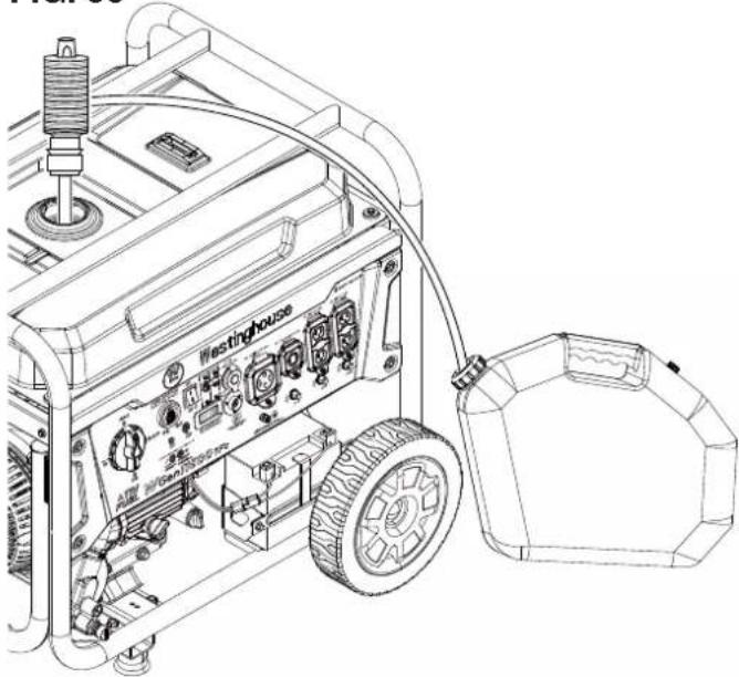
natural_image
Line drawing of a portable gas generator with attached circuit board and motor (no text or symbols)FIG. 37
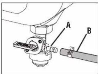
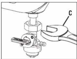
natural_image
Mechanical assembly diagram showing a wrench and nut assembly (no text or symbols)A - Fuel valve
B - Fuel line
C - 19 mm wrench (not included)
CHECKING/ADJUSTING THE VALVE CLEARANCE
See Figures 38 - 39.
NOTICE
Checking and adjusting valve clearance e when the engine is cold.
- Turn the generator off and allow the engine to cool for 30 minutes.
- Place the generator on a level surface in a well-ventilated area.
- Remove the rocker arm cover and carefully remove the gasket. If the gasket is torn or damaged, it must be replaced.
- Remove the spark plug so the engine can be rotated more easily.
- Pull the recoil handle to rotate the engine to top dead center (TDC). Looking through the spark plug hole; the piston should be at the top (both valves are closed).
- Both rocker arms should be loose at TDC on the compression stroke. If they are not, rotate the engine 360°.
- Insert a feeler gauge between the rocker arm and the valve stem to measure valve clearance.
| Intake Valve Exhaust Valve | ||
| Valve Clearance | 0.0031 – 0.0047 in (0.08 – 0.12 mm) | 0.0051 – 0.0067 in (0.13 – 0.17 mm) |
| Torque 8–1 | 2 Nm 8·12 Nm | |
- If an adjustment is necessary, hold the rocker arm pivot and loosen the pivot adjusting nut.
- Slide the appropriate feeler gauge between the rocker arm and the valve stem.
- Turn the rocker arm pivot to obtain the specified clearance. Hold the rocker arm pivot and re-tighten the pivot adjusting nut to the specified torque.
Torque: 106 inch-pound (12 Nm)
● Recheck valve clearance.
- If no further adjustments are needed, perform this procedure on the other valve.
- When finished, install the gasket, rocker arm cover, and spark plug.
FIG. 38
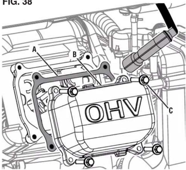
A - Gasket
B - Rocker arm cover
C - Bolt
FIG. 39
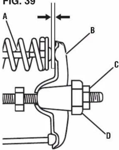
A - Valve stem
B - Rocker arm
C - Pivot adjusting nut
D - Rocker arm pivot
BATTERY MAINTENANCE
See Figure 40.
WARNING
The battery gives off explosive hydrogen gas during normal operation. A spark or flame can cause the battery to explode with enough force to kill or seriously hurt you. Wear protective clothing and a face shield, or have a skilled technician perform battery maintenance.
WARNING
Burn hazard. The battery contains sulfuric acid (electrolyte) which is highly corrosive and poisonous. Wear protective clothing and eye protection when working near the battery. Keep children away from the battery.
WARNING
NEVER smoke or work near sparks or other sources of ignition. NEVER touch both battery terminals at the same time with your hand or any non-insulated tools. If battery acid contacts skin or clothing, flush immediately with water and neutralize with baking soda.
The battery shipped with the generator has been fully charged. A battery may lose some charge when not in use for prolonged periods of time.
NOTE: Once started, the generator will charge the battery after 30–60 minutes of use.
When the generator is not running, the included trickle charger can remain connected and will maintain the battery for an indefinite period of time. A red light on the charger indicates charging in progress. A green light indicates charging complete. Charge in a dry location.
- Plug the charger into the battery charging port on the control panel.
● Plug the wall receptacle end of the battery charger into a 120 Volt AC wall outlet.
BATTERY REPLACEMENT
See Figure 41.
CAUTION
Battery posts, terminals contain lead and lead compounds. Wash hands after handling.
- Remove the wheel in front of the battery.
- Remove the two bolts and battery plate. Tilt the battery forward and remove.
- Disconnect the negative (−) cable (black boot) from the negative (−) battery post.
- Disconnect the positive (+) battery cable (red boot) from the positive (+) battery post.
NOTICE
Always connect the cables in the following sequence to avoid possible shock.
FIG. 40
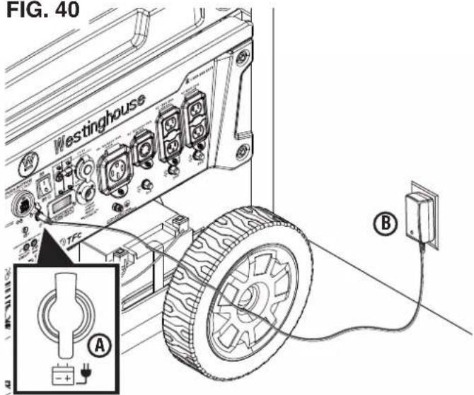
A - Battery charging port
B - Charger
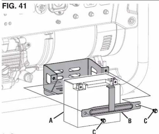
A - Battery
B - Battery plate
C - Bolt
- On the replacement battery, connect the positive (+) battery cable (red boot) to the battery positive (+) terminal. Secure the boot over the battery post.
- Connect the negative (−) battery cable (black boot) to the negative (−) positive terminal. Secure the boot over the battery post.
● Install the battery in the battery tray. Install the battery plate and bolts. Tighten the bolts securely.
NOTICE
Dispose of the used battery properly ac-e guidelines established by your local or ment.
Reinstall the wheel.
STORAGE
Turn the unit off and allow it to cool a minimum of 30 minutes before storage. Keep the unit upright. Do not store the generator on its side. Drain fuel before storing the unit. Store the unit and the fuel separately in well-ventilated areas away from sparks, open flames, pilot lights, heat, and other sources of ignition.
NOTICE
Gasoline stored for as little as 30 days can deteriorate, causing gum, varnish, and corrosive buildup in fuel lines, fuel passages, and the engine. This corrosive buildup restricts the flow of fuel, which can prevent the engine from starting after a prolonged storage period. The use of fuel stabilizer significantly increases the storage life of gasoline. Full-time use of fuel stabilizer is recommended. Follow the manufacturer's instructions for use.
| STORAGE TIME RECOMMENDED PROCEDURE | |
| Less than 1 month | Replace all protective covers on the generator control panel.Clean the exterior of the generator and remove any debris from the muffler cooling vents. |
| 2 to 6 months | Replace all protective covers on the generator control panel.Clean the exterior of the generator and remove any debris from the muffler cooling vents.Drain the carburetor float bowl. (Store gasoline in an approved gasoline container or dispose of it according to state and local ordinances.) |
| 6 months or longer | Replace all protective covers on the generator control panel.Clean the exterior of the generator and remove any debris from the muffler cooling vents.Drain the carburetor float bowl and the fuel tank.(Store gasoline in an approved gasoline container or dispose of it according to state and local ordinances.)Put a tablespoon of engine oil into the spark plug cylinder. Gently pull the recoil handle to slowly turn the engine and distribute the lubricant. Reinstall the spark plugChange the engine oil. |
MAINTENANCE SCHEDULE
Regular maintenance will improve performance and extend the service life of the generator. Follow the hourly or calendar intervals, whichever occurs first. More frequent service is required when operating in adverse conditions as noted below.
NOTE: If your product has a separate engine manual, disregard the information in this chart and follow the instructions in the engine manual.
| Before Each Use | After First 25 Hours or First Month | After 50 Hours or Every Six Months | After 100 Hours or Every Six Months | After 300 Hours or Every Year | |
| Check Engine Oil X | |||||
| Change Engine Oil ^1 | X | X | |||
| Clean Air Filter ^2 | X | ||||
| Inspect/Clean Spark Arrestor | X | ||||
| Inspect/Clean Spark Plug | X | ||||
| Inspect/Adjust Valve Clearance ^3 | X | ||||
| Replace Spark Plug | X | ||||
| Replace Air Filter X | |||||
| Replace Fuel Filter X | |||||
| ^1 Change oil every month when operating under heavy load or in high temperatures. ^2 Clean more often under dirty or dusty conditions. Replace air filter if it cannot be adequately cleaned. ^3 Recommend service to be performed by authorized Westinghouse service dealer. | |||||
Maintenance parts can be purchased directly from the factory. A partial list of maintenance parts is below. For a complete list of maintenance parts or for additional information email us at service@wpowereq.com or call 1-855-944-3571.
Air Filter 2126
Oil Drain Plug 91817
Drain Plug Washer 94004
Oil Dip Stick....485601-295
Spark Plug....97108

Do not use attachments or accessories that are not recommended for use with this product. d modifications and using incompatible accessories can damage the unit and void your warranty.
| PROBLEM POSSIBLE | CAUSE CORRECTION | |
| Engine starts, then shuts down | Fuel level is low or depleted. Add gasoline, connect natural gas hose, or connect propane cylinder. | |
| Low engine oil level stopped generator. Fill oil to proper level and ensure the generator is on a flat, level surface. | ||
| Dirty air filter. Clean the air filter. | ||
| Contaminated fuel source. Drain gasoline and refill the fuel tank, replace the propane cylinder, or have a professional clean the natural gas line. | ||
| Defective low oil level switch. Contact Westinghouse customer service toll-free at 1 (855) 944-3571. | ||
| Engine lacks power | Air filter restricted. Clean or replace air filter. | |
| The choke lever is in the wrong position. Move the choke lever to the correct position. | ||
| Fuel system malfunction, ignition malfunction, valves stuck, etc. | Contact Westinghouse customer service toll-free at 1 (855) 944-3571. | |
| Engine will not start | Fuel level is low or depleted. Add gasoline, connect natural gas hose, or connect propane cylinder. | |
| Stale gasoline, generator stored without treating or draining gasoline, or refueled with bad gasoline. | Drain the gasoline tank. Refuel with fresh gasoline. | |
| Dirty air filter. Clean the air filter. | ||
| Low engine oil level stopped generator. Fill oil to proper level and ensure the generator is on a flat, level surface. | ||
| Spark plug wet with fuel (flooded engine). Wait five minutes. Turn the fuel selector switch to the FUEL OFF position Pull recoil handle rapidly several times. If the generator does not start, remove spark plug and dry. | ||
| Spark plug faulty, fouled, or improperly gapped. | Gap or replace the spark plug. Reinstall. | |
| The fuel selector switch is in the FUEL OFF position | Turn the fuel selector switch to the appropriate position. | |
| CO sensor removed or modified. Return to original configuration. | ||
| CO sensor activated or system fault occurred. | Relocate generator / Contact Westinghouse customer service toll-free at 1 (855) 944-3571. | |
| Engine runs rough or bogs when load applied | Dirty air filter. Clean the air filter. | |
| Generator overloaded. Unplug some devices. | ||
| Faulty power tool or appliance. Replace or repair tool or appliance. Stop and restart the engine. | ||
| Fuel system malfunction, ignition malfunction, valves stuck, etc. | Contact Westinghouse customer service toll-free at 1 (855) 944-3571. | |
| No power at AC receptacles | AC circuit breaker/s tripped. Check AC loads and reset circuit breaker/s. | |
| Faulty power tool or appliance. Replace or repair tool or appliance. Stop and restart the engine. | ||
| Faulty generator. | Contact Westinghouse customer service toll-free at 1 (855) 944-3571. | |
WGen11500TFc
GENERADOR PORTÁTIL
GASOLINA: 11500 WATTS DE FUNCIONAMIENTO I 14500 WATTS PICO
PROPANO: 10500 WATTS DE FUNCIONAMIENTO | 13500 WATTS PICO
GAS NATURAL: 9500 WATTS DE FUNCIONAMIENTO | 12000 WATTS PICO
MANUAL DE USUARIO
NO DEVUELVA ESTE PRODUCTO A LA TIENDA
Westinghouse Outdoor Power
Warranty registration
777 Manor Park Drive
Columbus, OH 43228


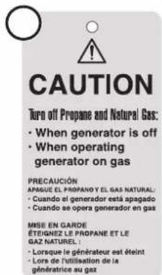
13
DANGER
PELIGRO
DANGER
Read User Manual before operating generator. Gasoline and LPG/Propane is highly flammable. Leaking gasoline or LPG can cause a fire or explosion if ignited. If you smell gasoline or propane while operating the unit, immediately shut OFF the fuel and/or propane valve. Keep gasoline container and propane tank away from exhaust.
Rinse with cleansing solvent and dry once every 50 hours (every 10 hours if operating in dusty conditions) and then immerse in clean engine oil until saturated. Squeeze out excessive oil,
A - Mango
PELIGRO
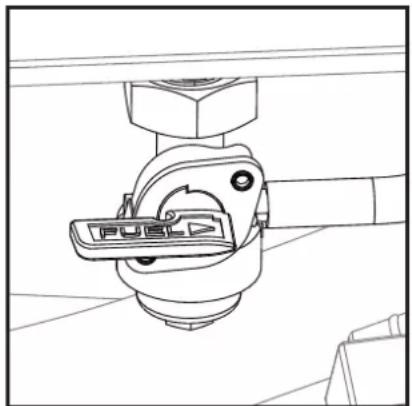
natural_image
Technical line drawing of a mechanical clamp or bracket assembly (no text or symbols)A - Válvula de combustible (abierta)
B - Válvula de combustible (cerrada)
FIG. 21
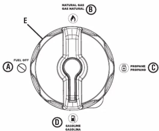
natural_image
Technical line drawing of a car engine bay with a hand adjusting the wheel (no text or symbols)natural_image
Technical line drawing of a mechanical component with a central circular feature and mounting base (no text or symbols)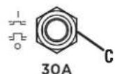
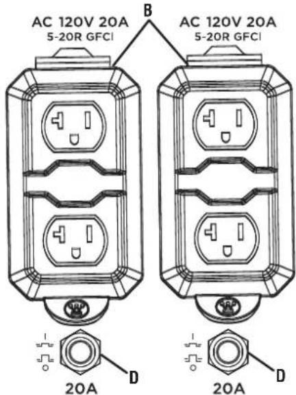
A - Cubierta del filtro de aire
B - Filtro de aire
C - Perilla
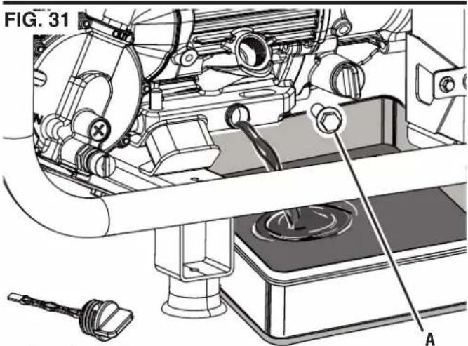
A - Filtro de aceite
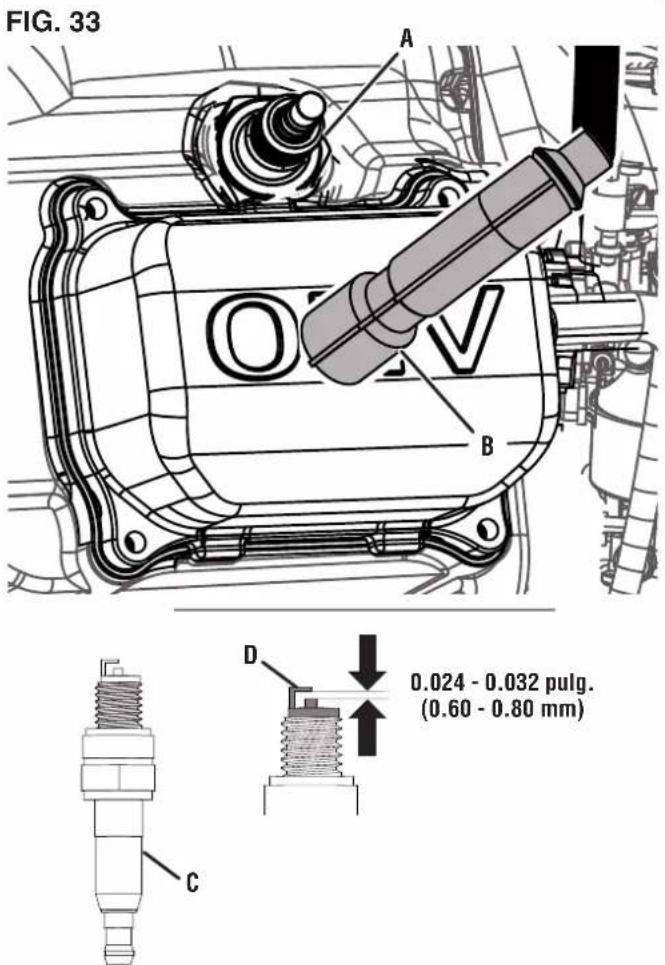
A - Bujía
natural_image
Line drawing of a portable gas generator with attached circuit board and motor (no text or symbols)FIG. 37
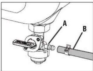
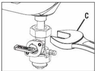
natural_image
Mechanical assembly diagram showing a wrench and nut assembly (no text or symbols)NE PAS RETOURNER CE PRODUIT AU MAGASIN
Westinghouse Outdoor Power
Warranty registration
777 Manor Park Drive
Columbus, OH 43228
Courant CA.... 95.8/47.9A (essence), 87.5/43.75A (propane), 78.3/39.1A (gaz naturel)
Tension CC....5V
Courant CC.... 2x2.1A
Fréquence 60 Hz
Phase ...... Single
Tr/min 3600
AVOIR DES QUESTIONS?
natural_image
Illustration of a hand using a tool to apply a mechanical component (no text or symbols visible)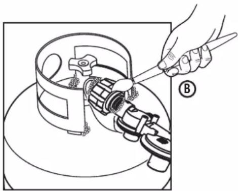
natural_image
Line drawing of a hand using a tool to adjust or install a mechanical component (no text or symbols present)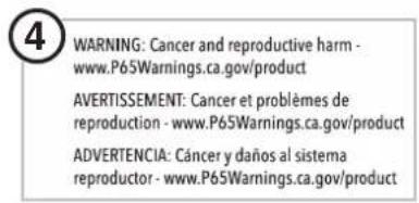

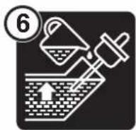


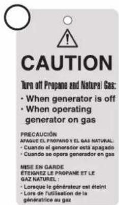

DANGER
▲ PELIGRO
DANGER
Read User Manual before operating generator. Gasoline and LPG/Propane is highly flammable. Leaking gasoline or LPG can cause a fire or explosion if ignited. If you smell gasoline or propane while operating the unit, immediately shut OFF the fuel and/or propane valve. Keep gasoline container and propane tank away from exhaust.
Rinse with cleansing solvent and dry once every 50 hours (every 10 hours if operating in dusty conditions) and then immerse in clean engine oil until saturated. Squeeze out excessive oil.
CAPACITÉ DU GÉNÉRATEUR
AVIS
PRISES 120 VOLTS C.A., 20 AMPÈRES
PRISES CA 120/240 VOLTS (50 AMP)
A - Bouchon de carburant
B - Jauge de carburant
FIG. 15
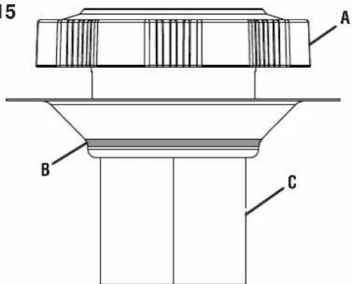
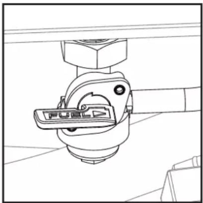
natural_image
Technical line drawing of a mechanical clamp or bracket assembly (no text or symbols)A - Filtre à huile
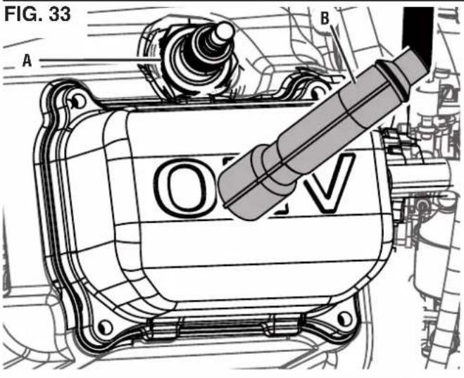
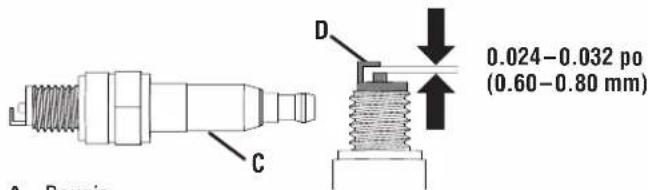
A - Bougie
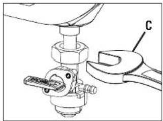
natural_image
Mechanical assembly diagram showing a wrench and nut assembly (no text or symbols)A - Soupape de carburant
B - Conduite de carburant
C - Clé (19 mm) [Non inclus]
FIG. 38
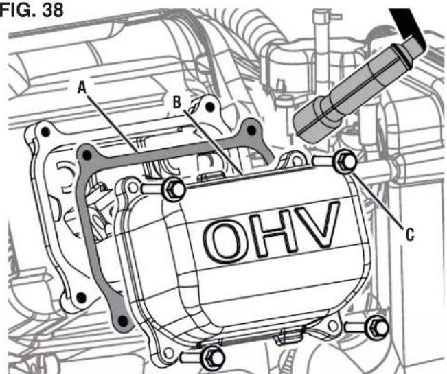
A - Joint
natural_image
Blue circular icon with a white crown and three dots, no text or symbols present.www.WestinghouseOutdoorPower.com
Service Hotline (855) 944-3571
777 Manor Park Drive, Columbus, OH 43228
and Westinghouse are trademarks of Westinghouse Electric Corporation.
Used under license by Westinghouse Outdoor Power Equipment.
© 2023 MWE Investments, LLC All Rights Reserved.