FX-AF2212 - Hand tool Fuxtec - Free user manual and instructions
Find the device manual for free FX-AF2212 Fuxtec in PDF.
| Product type | Petrol tiller |
| Brand | Fuxtec |
| Model | FX-AF2212 |
| Weight | 71.5 kg |
| Working width | 500 mm |
| Working depth | 175 - 350 mm |
| Engine type | OHV 4-stroke |
| Displacement | 212 cm³ |
| Power | 7.0 hp (4.3 kW) at 3600 rpm |
| Fuel tank capacity | 3.6 L |
| Oil tank capacity | 0.6 L |
| Recommended fuel | Unleaded petrol |
| Recommended engine oil | SAE 10W-30 |
| Sound pressure level (LPA) | 83.20 dB(A), k=3 dB(A) |
| Guaranteed sound power level (LWA) | 101 dB(A) |
| Vibrations (hand/arm) | Left: 2.226 m/s²; Right: 2.596 m/s²; Uncertainty: 1.5 m/s² |
| Starting system | Recoil start |
| Transmission | Forward, reverse, neutral |
| Depth adjustment | Depth control lever |
| Safety | Safety lever, engine stop, debris protection |
| Routine maintenance | Oil check and change, air filter cleaning, belt check, axle greasing |
| Warranty | 24 months |
Frequently Asked Questions - FX-AF2212 Fuxtec
User questions about FX-AF2212 Fuxtec
0 question about this device. Answer the ones you know or ask your own.
Ask a new question about this device
Download the instructions for your Hand tool in PDF format for free! Find your manual FX-AF2212 - Fuxtec and take your electronic device back in hand. On this page are published all the documents necessary for the use of your device. FX-AF2212 by Fuxtec.
USER MANUAL FX-AF2212 Fuxtec
natural_image
Line drawing of a tracked utility tiller with visible blade and bushing (no text or symbols)natural_image
Orange and black utility tiller with visible mechanical components (no text or symbols)natural_image
Orange stylized graphic of a running figure next to a turtle on dark background (no text or symbols)212ccm
EASY TO START
OHV MOTOR
LUFTFILTER
text_image
Labeled diagram of a manual lawn mower with numbered parts for identificationnatural_image
Close-up of a red tire with mechanical components and a cylindrical component attached (no visible text or symbols)2
natural_image
Close-up of a red industrial tire with a central circular component and metal fittings (no visible text or symbols)natural_image
Close-up of an orange and black tiller with visible blades and wheels, parked on a plain floor (no text or symbols)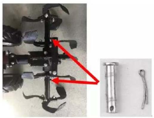
natural_image
Mechanical component with red arrow indicating a joint or connection point, alongside two metallic tool parts (no text or symbols visible)natural_image
Red surface with yellow directional arrows and black circular markers, no visible text or symbols
natural_image
Red tractor with attached mechanical components and blue alignment arrows indicating assembly or alignment (no text or symbols)text_image
Technical diagram of a mechanical assembly with labeled parts A, B, and C6.6 Installieren des Lenkers
text_image
Technical diagram of a U-shaped magnet with labeled components A, B, C, D and a magnified view showing internal structure.natural_image
Close-up of a black industrial machine with visible blades and control panel, showing red arrows indicating motion or movement (no text or symbols)natural_image
Metallic industrial component with red arrows indicating flow or movement, no visible text or symbols7. Inbetriebnahme
text_image
Technical diagram showing a U-shaped mechanical component with labeled parts A, B, C, and D, including a close-up of a mechanical assembly.text_image
Technical diagram of a mechanical assembly with labeled parts A, B, and CWe are pleased about your confidence!
Please read these instructions for use before the first operation and before every use!
Here you will find all instructions for safe use and a long lifetime of the device. Be sure to observe all safety instructions in these instructions!
Please always keep this instruction manual together with the device to have it at hand in case of doubt.

natural_image
Orange and black utility tiller with visible blades and control unit (no text or symbols)| Please note! | Carefully read and follow all instructions in this manual before using the tool.Always keep the user manual at hand during work. |
CE
FUXTEC GmbH
Kappstraße 69, 71083 Herrenberg, Germany
Table of contents
- Intended/non-intended use 37
- General Safety Instructions.... 39
- Special Safety Instructions.... 42
- Description of security symbols.... 43
- Presentation 49
- Assembly instructions.... 50
- Commissioning.... 55
- Care and Cleaning 61
- Technical data.... 65
- EC Declaration of Conformity.... 66
You can download the corresponding engine manual at www.fuxtec.com on the article page.
11. Intended/non-intended use
The petrol-driven engine hoe is used exclusively to loosen or dig up loamy soil in the garden area, up to the hoe tool's maximum working depth. The device may only be used in open garden areas. The user manual must be read before each use. Sufficient protective equipment must be provided by following the user manual and the warning pictograms attached to the device. Only original spare parts specified by the manufacturer may be used. The use of other components or attachments on the engine hoe will lead to an expiration of the manufacturer's liability for personal injury and material damage.
All other applications, places of use not mentioned above, and not observing the user manual of the petrol-driven engine hoes are considered improper use of the device. The user/operator and not the manufacturer is liable for damages or injuries resulting from misuse.
Residual dangers
Even if the device is used correctly, there is always a particular residual risk that cannot be excluded. Due to the use mentioned above and the device's construction, the following potential hazards may be derived during use.
- Impact of body parts or running over feet during transport
- Contact with the open hoe tool
- Contact with the running hoe tool
- Unforeseen movement of the device (getting caught in roots or similar)
- Throwing away stones or loam chunks
- Damage to the hearing, if not sufficient hearing protection is worn
- Inhalation of clay soil dust; exhaust gases from the combustion engine
- Contact with gasoline or lubricants on the skin
Warning: The present existing vibration emission value during the device's use may differ from the user manual's value or manufacturer. That can be caused by the following influencing factors, which should be considered before or during use:
- If the device is used correctly
- Is the way of cutting the material or how it is processed correctly
- Is the device in good working condition
- The sharpness of the cutting tool or correct cutting tool
- Are the grips, if necessary, optional vibration grips mounted, and are they fixed to the device body
If you experience an unpleasant feeling or skin discolouration on your hands while using the device, stop working immediately. Take sufficient breaks from work. If you do not take sufficient breaks, a hand-arm vibration syndrome can occur.
An estimation of the degree of stress depending on the device's work or use should be made, and appropriate work breaks should be inserted. In this way, the degree of stress can be significantly reduced during the entire working time. Minimize your risk of being exposed to vibrations. Take care of this device according to the instructions in the user manual. If the device is used frequently, you should contact your
dealer and get anti-vibration accessories (handles). Avoid using the device at temperatures of t=10^ or less. Make a work plan to limit the vibration load.
The device corresponds to science and technology and the valid safety regulations when placing on the market within its intended use.
This device may only be used with the approved original milling wheels for outdoor lawn and fieldwork. The device is not designed for commercial use. Any other use is contrary to its intended purpose. Unauthorized use, modifications to the device, or the use of parts that have not been tested and approved by the manufacturer may result in unforeseeable damage! Any improper use or any activities on the device not described in these operating instructions are unauthorized misuses outside the manufacturer's legal liability limits.
12. General Safety Instructions
RESPONSIBILITY OF THE USER
Correct installation and safe, efficient use are the responsibility of the user.
- Read and follow all safety instructions
- Follow all Assembly instructions
- Take care of the device as described in this manual and keep to the schedule
- Make sure that each person operating the device is familiar with the control system and safety precautions
The engine hoe must always be used according to the manufacturer's instructions in the instruction manual.

WARNUNG
e. Read the instructions carefully. Familiarize yourself with the controls and the proper use of the device.
f. Never allow children or persons unfamiliar with these instructions to use this device. Local regulations may limit the age of an operator.
g. Never work with the device if there are persons, especially children or pets, in the vicinity.
h. Note that the operator or user is responsible for accidents and damage caused to other people or their property.
Preparation
f. Always wear robust shoes and long pants when working. Never wear open sandals when operating the device and never operate the device barefoot.
g. Check the device to be used very carefully and remove all objects
that the device can throw up.
h. WARNING Gasoline is highly flammable:
- store fuel only in approved containers;
- Refuel only outdoors and do not smoke;
- Refuel before starting the engine. Never remove the filler cap and never refuel while the engine is running or when the engine is hot;
- If fuel is spilt, do not attempt to start the engine; instead, remove the device from the spillage area and avoid the formation of ignition sources until the fuel vapours have evaporated; replace the fuel cap and all container caps securely.
i. Replace damaged mufflers;
j. Always visually inspect tools to ensure that they are not worn or damaged before use. Replace worn or damaged parts and screws in sets to avoid imbalance.
Operation
o. Do not operate the engine in enclosed areas where dangerous carbon monoxide may collect.
p. Work only in daylight or under good artificial lighting.
q. Always ensure that you are sure-footed when working on a slope.
r. You must never run with the device, only walk.
s. Never work with devices with rotating parts and wheels, always cross the slope, never up and down.
t. Always take extreme caution when changing direction on slopes.
u. Do not work on too steep gradients.
v. Be extremely careful when walking backwards or pulling the device towards you.
w. Do not change the engine controller setting, and do not run the engine with excessive speed.
x. Start the engine carefully according to the manufacturer's instructions, ensuring that your feet are far enough away from the tool(s).
y. Do not place your hands or feet near or under rotating parts.
z. Never pick up a device or carry it while the engine is running.
aa. Switch off the engine:
- when you leave the device alone
- before refuelling
bb.Depressurize the throttle while turning off the engine; if the engine is equipped with a fuel tap, close it after finishing the work.
Maintenance and storage
g. Ensure that all nuts, bolts, and screws are tightened to ensure that the device is always in a safe condition.
h. Never store the device with a full or partially filled tank in a building where fuel vapours can reach an open flame or spark.
i. Allow the engine to cool down before storing the device in a container.
j. Keep the engine, muffler, battery compartment, and fuel storage area free of vegetable materials and excessive grease to reduce fire risk.
k. For safety reasons, replace worn or damaged parts.
I. If the fuel tank needs to be drained, do so outdoors.
13. Special Safety Instructions
- Always wear robust shoes and long pants when working. Do not operate the device while wearing open sandals or walking barefoot.
- Check the area where the device is to be used and remove all objects thrown up by the device.
- Ensure that the tools are not worn out or damaged by visual inspection. Always replace worn or damaged blades and screws in sets to avoid imbalance.
- When carrying out maintenance and cleaning work, the engine must be switched off when changing tools and transporting the device (except for self-drive).
- Working on slopes can be dangerous.
- When working on difficult soils (stony or hard ground), special dangers may occur.
- Properly trained persons may only use the device.
- Safety shoes must be worn when operating the device.
- Limit the use and wear safety equipment to reduce vibration-related dangers.
14. Description of security symbols
This device has been designed with the safety and reliability you would expect from a market leader.
We have attached several safety instructions to the device to draw your attention to the most critical points during operation. However, all necessary safety instructions are already included in this manual.
These safety badges are explained below and presented here to familiarize yourself with the location and contents. Please take a moment to go through these plaques now. If you have any questions regarding the meaning, please read the previous pages or contact your dealer.
If some badges become illegible due to abrasion, fade, or are otherwise damaged, you should find all badges illustrated in this manual.
These instructions are easy to follow and will continuously remind you and others what to observe. Follow all instructions to ensure the safe and effective operation of the device.
Warnings/Assistances
Table 1)
1 | 1 | 2 | 3 |
4 | 5 | 6 | 7 |
8 | 9 | 10 | 11 |
12 | 13 | 14 | 15 |
16 | 17 | 18 | |
The following symbols are used in this manual and on the device:
Table 1)
- There is a risk of injuring yourself or damaging the tool.
- Please read the operating instructions before use.
- Wear industrial-grade hearing protection for noise protection.
- Wear safety goggles to protect your eyes.
- Wear sturdy safety shoes.
- Keep uninvolved persons away.
- Gasoline is flammable. Allow the engine to cool for at least 2 minutes before adding fuel.
- NEVER touch the hot components such as the silencer.
- Wear gloves.
- In compliance with basic safety standards within the scope of applicable European directives.
- No open flames.
- No smoking!
- Risk of injury.
- Warning! Flying objects.
- Engines emit carbon monoxide, DO NOT operate them indoors.
- Add oil up to the upper-level indicator mark to start. The engine does not create or shuts off when the oil level is low.
- Top up oil here.
- Speed setting from low (tortoise) to high speed (hare).

text_image
FUXTEC 212ccm OHV
natural_image
Orange stylized graphic of a running figure next to a turtle on dark background (no text or symbols)212ccm
EASY TO START
OHV MOTOR
LUFTFILTER
Please clean the air filter every 50 operating hours

WARNUNG!
- explosive and highly flammable fuel
- before refuelling, switch off the unit and allow it to cool down
- Caution: Exhaust gases contain toxic carbon monoxide
- do not use indoors
- read manual before use

text_image
CHOKE ← LAUF AUS ← EIN
Choke - Run

Off - On

text_image
LWA 101 dB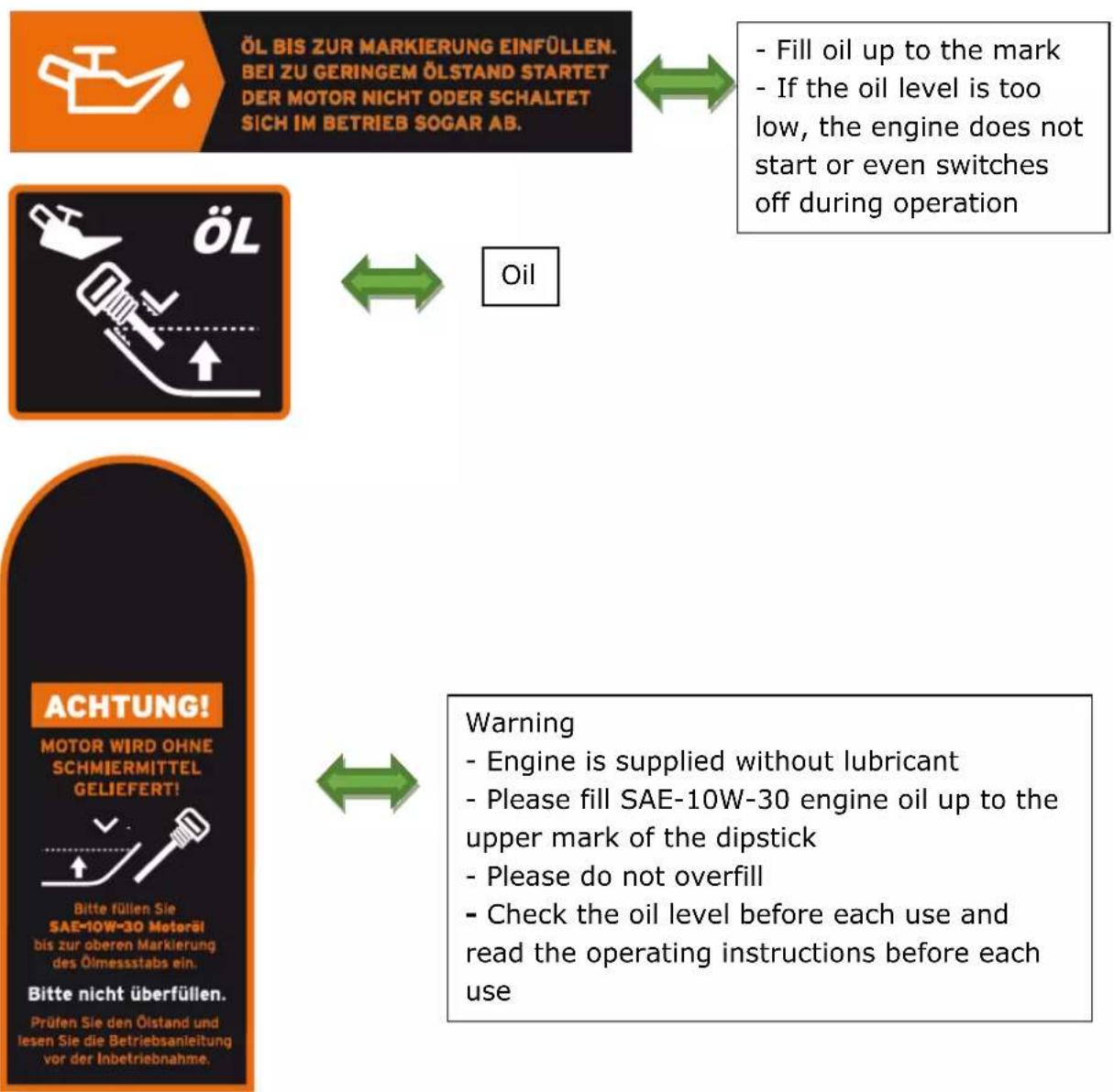
natural_image
Illustration of a hand turning a gear with motion arrows, symbolizing mechanical or robotic operation (no text present)- read manual before use
- explosive and highly flammable fuel.
Before refuelling, switch off the unit and allow it to cool down
- Exhaust gases contain toxic carbon monoxide. Do not inhale.
- Temperature in the silencer area can reach up to 70 degrees.
Please do not
Danger
- Avoid injuries from rotating parts
- Keep hands, feet and clothing away from it
RÜCKWÄRTS

Reverse
VORWÄRTS

Forwards
15. Presentation
text_image
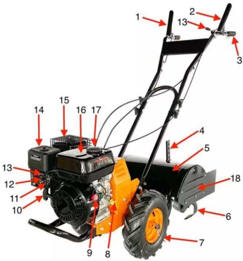
Labeled diagram of a manual lawn mower with numbered parts for identification| 1 | Forward lever | 10 | Pullstarter |
| 2 | Reverse lever | 11 | Fuel lever |
| 3 | Handlebars | 12 | Choke lever |
| 4 | Depth regulator | 13 | Throttle lever |
| 5 | Mudguard | 14 | Air Filter |
| 6 | Blade | 15 | Silencer |
| 7 | Wheel | 16 | Fuel tank |
| 8 | Oil filling | 17 | Fuel filler cap |
| 9 | On/Off switch | 18 | Side guard |
16. Assembly instructions
The petrol tiller is delivered fully assembled except for a few parts. The following instructions will help you assemble and adjust the petrol rotary cultivator.
16.1 Checking the contents of the packaging
- Remove all packing materials.
- Remove any remaining packaging materials and package inserts (if included in the delivery scope).
- Check that all parts are undamaged and complete.
- If possible, keep the packing material until the rifle performance period. You can then take it to your local recycling centre.
WARNUNG! Packaging materials are not toys! Do not let children play with plastic bags! There is the danger of suffocation!
If parts are missing or damaged, please contact FUXTEC at info@fuxtec.co.uk
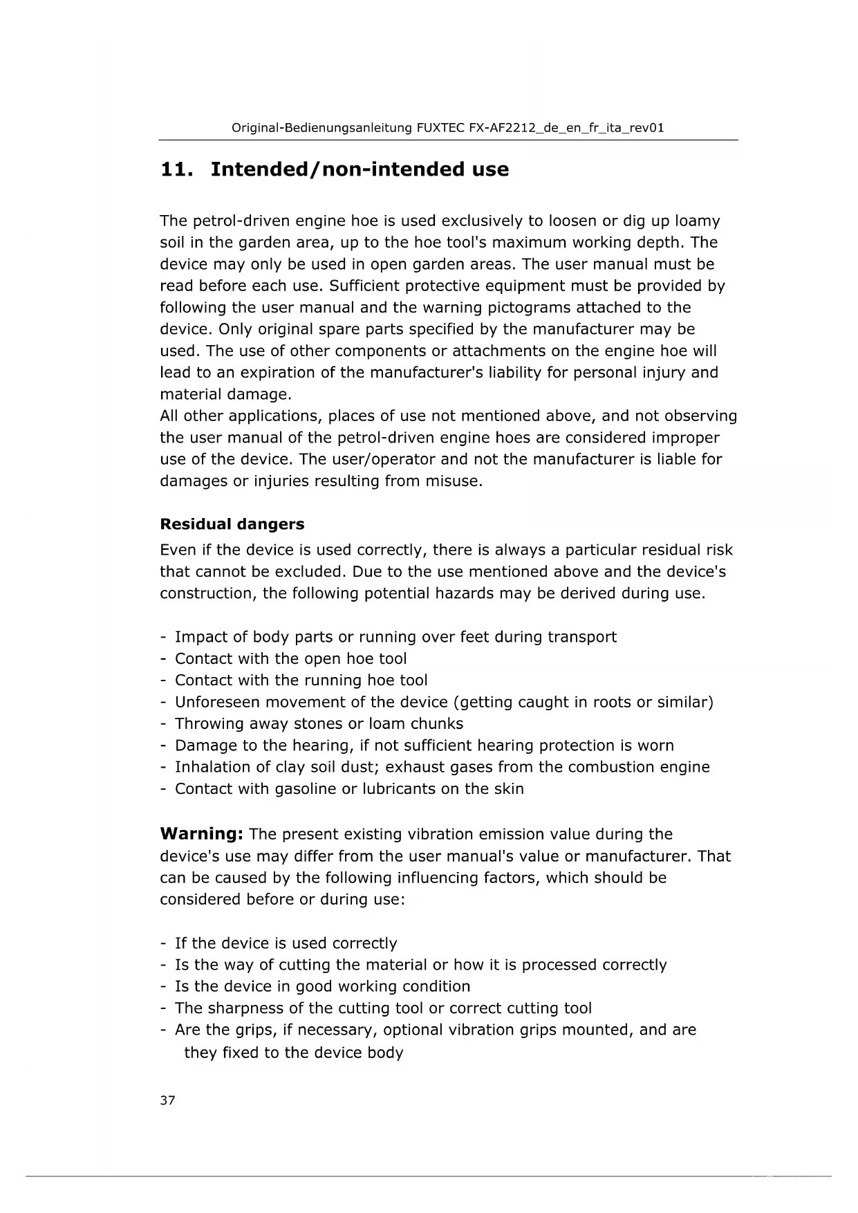
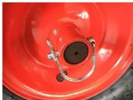
16.2 Installing the wheels
4
1

natural_image
Close-up of a red tire with mechanical components and a cylindrical component (no visible text or symbols)2

natural_image
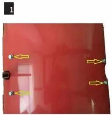
Close-up of a red industrial tire with metal clamps and a central circular component (no visible text or symbols)Place the tires on the axle.
- Freewheel position: Insert the locking pin only through the axis's hole (see Fig. 1).
- Milling position: Insert the locking pin through the provided hole of the wheel hub as well as through the hole of the axle, thus connecting axles and tires (see picture 2)
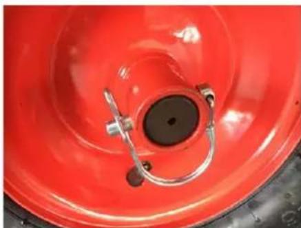
16.3 Installing the chipper knives
Install the chipper knives on the axle's left and right sides and fix them with a straight pin and a split pin (see the following picture).

natural_image
Close-up of an orange agricultural tiller with four blades and a large wheel, placed on a concrete floor (no text or symbols visible)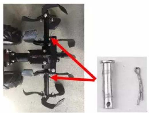
natural_image
Close-up of a mechanical tool with a red arrow pointing to a component, alongside two metallic tools (no visible text or symbols)16.4 Installing the guard plate and the side guard plate
- Attach the mudguard and fasten it with 4 screws.
- Attach the side mudguard.
natural_image
Red surface with yellow directional arrows and dots, no visible text or symbols
natural_image
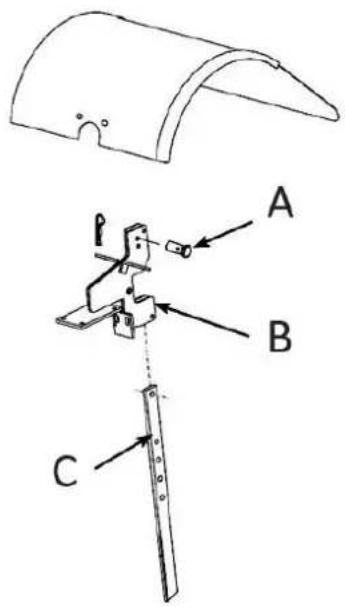
Red tractor with attached mechanical components and blue arrows indicating alignment or assembly (no text or symbols)16.5 Installing the depth regulator
- Attach the depth regulator to the top of the depth regulator holder. The handle should point to the rear.
- Insert the dowel pin through the depth regulator bracket and the depth regulator hole fixed with a B pin - the chopper blades should not touch the ground.
text_image
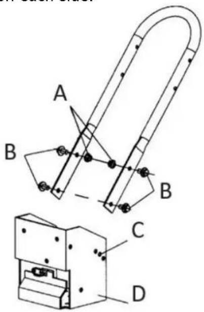
Technical diagram of a mechanical assembly with labeled parts A, B, and C16.6 Installing the handlebar
- Insert the handlebar arm outside the transmission cover and align the lower holes.
- Insert the bolts and nuts for each side into the lower holes.
- Insert the bolt and nut for each side into the upper holes at the desired handlebar height.
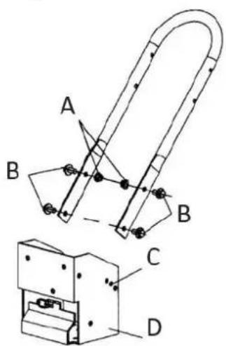
text_image
Technical diagram showing a U-shaped mechanical component with labeled parts A, B, C, D and a close-up view of a mechanical assembly.| A | Locknuts |
| B | Height adjustment screw |
| C | Holes for height adjustment |
| D | Transmission cover |
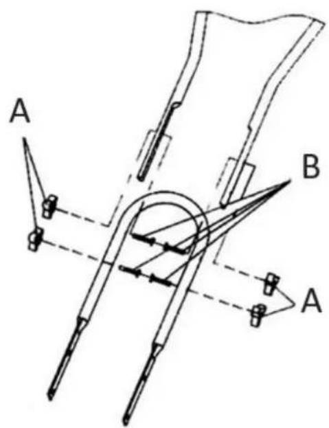
16.7 Installing the handlebar
- Insert the four mounting bolts into each hole on each side.
- Place the mounting nuts on each bolt.
- Tighten all nuts.
text_image
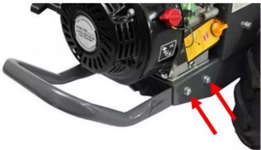
A B A16.8 Installing the front bar
natural_image
Close-up of a black and white industrial machine with visible components and red directional arrows indicating motion or force (no text or symbols)• Install the front handle and secure it with 4 bolts and nuts each.
16.9 Installing the protective grille cover of the Silencer
- Remove the two screws from the muffler and install the protective grill cover. Fasten it with the screws.
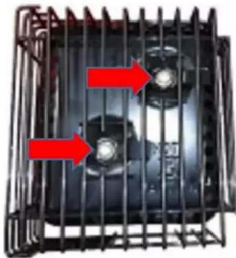
natural_image
Close-up of a black industrial fan or motor unit with red arrows indicating flow direction (no text or symbols visible)17. Commissioning
CHECK BEFORE THE START
1) Ensure that all protective covers are mounted and all screws and nuts are fixed.
2) Check the oil level in the engine housing. Please refer to the engine manual.
3) Check that the air filter is clean, please follow the engine manual
4) Check the fuel level. Fill in no more than 2.5 cm from the top so that the gasoline can still expand.
5) Ensure that the spark plug connection is mounted and the spark plug is firmly fixed.
6) Check the position of the wheels and the wheel lock
7) Check the setting of the depth regulator lever.
8) Check the bottom and the engine environment for oil or fuel leaks.
9) Check the fuel lines for tightness and possible leaks.
10) Check the engine for damages.
11) Remove deposits in the area of the exhaust and pullback starter.

VORSICHT
- Open the fuel lever.
- Move the throttle lever to the start position.
- Turn the switch to ON.
- Move the throttle lever to the middle position.
- When the engine starts, gradually set the throttle to "no choke."
17.1.2 Warm start of the engine
Restarting an already warm engine from a previous operation does not usually require the choke's use.
- Turn the switch to ON.
- Pull the starter rope out quickly until the engine starts.
- Set the throttle to "high" to get the best milling performance.
17.2 Idle speed
Using the "low" position on the throttle lever, you can reduce the engine load when you are not currently milling. Lowering the engine speed to "idle" will extend the engine's life. Follow the same procedure to save fuel and reduce the device's noise level.
17.3 Shutting down
To stop the engine at any time, move the engine ON / OFF switch to the OFF position.
To stop the wheels and chipper blades at any time, move the clutch levers to the neutral position.
17.4 Milling
- Set the depth control lever to the desired machining depth.
NOTE: Raise the depth control lever one hole at a time. Test the functionality of the petrol rotary cultivator after each hole. Raising the
depth control lever too high may result in loss of control of the tiller!
- Set the throttle lever to high.
- Place the petrol tiller in the forward position by pushing the clutch lever down (FORWARD). That will engage the wheels and chipper blades.
NOTE: You can slow the petrol rotary cultivator's forward motion at any time by pushing the handlebars down slightly. You can stop the petrol rotary cultivator by moving the clutch lever to the idle position.
17.5 Safety lever
CAUTION:
Never operate the forward and reverse clutch levers simultaneously (see Figure Presentation No.1 and 2.).
17.5.1 Forward lever
- Engage the wheels and chipper blades to move forward.
- Pushing the FORWARD lever toward the handlebar will engage the wheels and chipper blades.
- Releasing the lever will stop the wheels and hoeing blades and bring the petrol tiller to a stop.
17.5.2 Reverse lever
- Engage the wheels in reverse gear.
- Push the reverse lever toward the handlebar to engage the tiller in reverse gear.
- Releasing the lever stops the wheels.
17.6 Adjustments
The engine should be turned off before making any adjustments. Extreme caution should be used when operating the tiller in reverse.
17.6.1 Wheel lock pins
Move wheels to milling position:
- Remove locking pin. Align the hole in the axle with the hole in the wheel hub.
- Insert the locking pin through the holes and attach the locking pin ring to secure the axle's pin.
- Lock the wheel and axle firmly together before milling.
- Repeat for the other wheels.
NOTE: Always have both locking pins inserted or pulled out. Do not operate the router with only one wheel secured.
Move wheels to freewheel position:
- Remove locking pin. Push the wheel inward toward the device.
- Insert the pin into the axle only.
- The wheel should be able to rotate freely on the axle.
17.6.2 Height adjustment of the handlebars
The ideal height of the handlebar depends on the operator size and the machining depth.
Adjusting the handlebar:
- Loosen the nuts and remove the top bolts on each side.
- Align the handlebar with the desired holes.
- Replace and tighten the bolts and nuts.
| A | Locknuts |
| B | Height adjustment screw |
| C | Holes for height adjustment |
| D | Transmission cover |
text_image
Technical diagram of a mechanical device with labeled components A, B, C, D and a separate view showing internal structure.17.6.3 Depth control lever

text_image
Technical diagram of a mechanical assembly with labeled parts A, B, and C| A | Dowel pin | C | Depth regulator |
| B | Depth regulator bracket | ||
The milling depth is controlled by the height of the depth control lever. To adjust the machining depth:
- Loosen the depth regulator screw.
- Adjust the depth control lever so that the chipping knives are at the selected machining depth.
- Tighten the screw of the depth regulator. Depth control lever down = lower milling.
Insert the depth control lever screw into the depth control lever's upper hole for the lowest machining depth.
Depth control lever up = deeper milling.
Insert the screw of the depth regulator into the lower hole of the depth regulator lever for the most profound machining depth.
17.6.4 Adjusting the belt tension
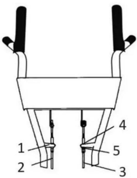
text_image
1 2 3 4 5| 1 | Bracket | 2 | Forward cable |
| 3 | Reverse cable | 4 | Upper lock nut |
| 5 | Lower lock nut |
Proper belt tension is critical for good work performance. After half an hour of operation, all belts may need adjustment due to initial stretch. After that, you should check the tension after every 2 hours of operation.
To increase the belt tension:
- Loosen the upper jam nut and unscrew the nut.
• Tighten the lower lock nut. - Check the adjustment.
This process can be repeated until the tube adjustment screws are fully adjusted. If no further adjustments can be made, the belt must be replaced.
18. Care and Cleaning
18.1 Storage
- Protect the wheels and axles from rust:
- Remove the locking pin and slide the wheel off the hub.
- Lightly coat the axles with axle grease.
- Slide the wheel back onto the hub and install the locking pin.
- Drain the fuel system completely. Follow the engine manufacturer's instructions for this. Add a fuel stabilizer to prevent the fuel from becoming unusable during an extended storage period.
- The engine must be warm while the oil is drained from the engine. Refill with fresh oil of a recommended type.
- Clean the exterior surfaces, engine, and fan.
- Remove the spark plug, pour one ounce of SAE 30 oil into the spark plug hole.
- Plug the hole and slowly pull the starter cable to distribute the oil evenly throughout the cylinder head area.
- Reinstall the spark plug.
- Move the device to a suitable storage location. If you choose to use a fuel stabilizer and have not drained the fuel system, follow all safety instructions and storage precautions in this manual. This will reduce the fire risk due to the ignition of gasoline vapours. Remember that gasoline vapours can travel to distant ignition sources and ignite, causing explosions and fires.
- If there is a possibility of unauthorized use or tampering, remove the spark plug and store it safely before storing the petrol tiller. Be sure to plug the spark plug hole to prevent foreign objects from entering.
18.2 Disposal
- When the device needs to be replaced after prolonged use, do not dispose of it in household waste. Dispose of it in an environmentally friendly manner.
- Please dispose of used engine oil in an environmentally friendly manner. We recommend taking it to your local recycling centre in a sealed container for recycling. Please do not throw it into the household waste garbage can, and do not pour it on the ground.
18.3 Maintenance schedule
Keeping the petrol rotary cultivator in proper operating condition will extend its service life and ensure that you always get optimum work performance.
Please read this general maintenance schedule and follow the recommended maintenance intervals to extend your device's life.
| Maintenance and operation | Each use | The first month or 20 hours | Every 3 months or 50 hours | Every 6 months or 100 hours | Every year or 300 hours | |
| Belt tension | Check | √ | ||||
| Change. | √ | |||||
| Check Engine oil | level | √ | ||||
| Change. | √ | √ | ||||
| Check | Air filter | √ | ||||
| Clean | v(1) | v(1) | ||||
| Replace | √ | |||||
| Lubricant for the gearbox of the rotary cultivator. | Check | √ | ||||
| Replace | √ | |||||
| Check | Tire pressure | √ | ||||
| Clean | Chopper shaft | √ | ||||
| Axle shaft | Lubricant | √ | ||||
| (1) Service the equipment more frequently when using it in a dusty environment. | ||||||
18.4 Troubleshooting
While ordinary care and routine maintenance will prolong the device's life, prolonged or constant use may eventually require professional service and maintenance to maintain proper operation. The troubleshooting guide below lists the most common problems, causes, and solutions.
| Problem | Solution/ Troubleshooting |
| The engine does not start | Add gasoline to the fuel tank.Connect the spark plug wire to the spark plug. |
| ·The throttle must be in a choke position for a cold start. | |
| Engine runs erratically or stops during operation. | ·Clean or replace the air cleaner. |
| The engine is difficult to start. | ·Drain old fuel and replace it with fresh. Use a fuel stabilizer at the end of the season. ·Make sure the spark plug wire is firmly connected to the spark plug. ·To start the engine, the driving safety levers must be moved to the idle position. |
| Lack of or insufficient engine power. | ·Raise the shallow tillage chopping blades by lowering the depth control lever. ·Remove and clean the fuel tank. ·Clean or replace the air cleaner. ·Improper carburettor adjustment - contact an authorized engine repair shop. ·Replace the spark plug and adjust the gap. ·Drain and refill the fuel tank and carburettor. |
| The engine does not stop when the throttle is in the stop position. | ·Refer to the engine operator's manual to check and adjust the throttle. |
| Tiller moves forward when started. | ·To start the engine, move the travel safety levers to the idle position. |
| Tiller is challenging to control when milling (device jumps or stalls forward). | ·Lock the wheels in the milling position. ·Raise the hoeing blades for shallower tillage by lowering the depth control lever. |
| Hoeing knives turn, but wheels do not turn. | ·Lock the wheels in the milling position. ·Internal transmission failure contact your dealer. |
| Chopping knives and wheels turn, but the tiller does not move. | ·Lower the chopping blades for a deeper tillage depth by raising the depth control lever. |
| Belts squeal when idling and in reverse. | Adjust the front belt guide:Stop the engine and allow the muffler to cool.Disconnect the spark plug wire and pull it off the spark plugRemove the belt guardPull down the drive safety control levers.Manually bend the belt guide forward, leaving 1/16 inch or less of slack between the belt guide and the beltReplace the belt guard and spark plug wire |
| Belts squeal in forwarding operation. | Adjust the tabs on the rear belt guide.Stop the engine and allow the muffler to cool.Disconnect the spark plug wire and pull it off the spark plugMove the drive safety levers to the idle positionRemove the belt guardAdjust the belt return tabs |
| With the drive safety control levers released bend the metal tabs on the reverse belt guide to 1/64 or less from the reverse belt.Replace the belt guard and spark plug wire | |
| Excessive heat builds up in the gearbox/chipper blade area during milling. | Remove accumulated plant debris by following the General Care section's instructions of the chipper blade shaft. Observe all safety instructions.Check the gearbox oil and top up if necessary. |
- Technical data
| Device | FX-AF2212 | Oil quantity | 0.6 L |
| Max. Power | 4.3 KW | Fuel type | Unleaded gasoline |
| Weight | 71.5 Kg | Vibration | L: 2.226 m/s ^2 R: 2.596 m/s ^2 |
| Working range | 500 mm | Vibration uncertainty | 1.5 m/s ^2 |
| Machining depth | 175~350 mm | ||
| Gear shift | 0, 1, -1 | Sound power level (LWA) | 97.14 dB(A), k=3 dB(A) |
| Engine type | OHV 4-stroke | Guaranteed sound power level LWA | 101 dB(A) |
| Starting system | Recoil | ||
| Displacement | 212 ccm | ||
| Max. Output | 7.0 hp/3600rpm | ||
| Engine speed | 3,600 rpm | ||
| Fuel quantity | 3.6 L | ||
20. 20. EC Declaration of Conformity
Herewith we,
FUXTEC GmbH
Kappstrasse 69, 71083 Herrenberg - Germany
Declare that the device designated below, the
FX-AF2212 rotary cultivator,
relates to the applicable EC Directives 2006/42/EC's relevant essential health and safety requirements. This declaration refers only to the device in the condition in which it was placed on the market. Parts and interventions subsequently fitted by the end-user are not taken into account.
Applicable EC Directives
Directive 2010/26/EC
Directive EMC 2014/30/EU
Noise Emissions Directive 2000/14/EG
with the application of 2005/88/EC
CE Certificate number AM 50518927 0001 /
AE 50519996 0001
Conformity procedure according to Annex V / Directive 2000/14/EC
Herrenberg, March 27, 2022
Tian Gumpred
Tim Gumprecht
(Managing Partner)
Manufacturer:
FUXTEC GmbH
KAPPSTRASSE 69
71083 HERRENBERG
GERMANY
Retention of technical documentation:
FUXTEC GmbH • Kappstrasse 69 • 71083 Herrenberg • Germany
Tim Gumprecht, Managing Director
Chère cliente, cher client,
Avertissements/Assistances
Tableau 1)
1 | 1 | 2 | 3 | ||
4 | 5 | 6 | 7 | ||
8 | 9 | 10 | 11 | ||
12 | 13 | 14 | 15 | ||
16 | 17 | 18 | |||
natural_image
Orange stylized graphic of a person running with a car icon, no text or symbols presentFiltre à air
text_image
Labeled diagram of a manual lawn mower with numbered parts for identificationnatural_image
Close-up of a red tire with mechanical components and a small cylindrical object on top (no visible text or symbols)2
natural_image
Close-up of a red industrial tire with metal clamps and a central circular component (no visible text or symbols)natural_image
Close-up of an orange agricultural tiller with black blades and a large wheel, parked on a concrete floor (no visible text or symbols)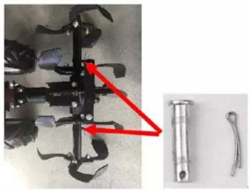
natural_image
Mechanical component with attached pin and two separate metal parts (no visible text or symbols)natural_image
Red surface with two small arrows pointing to features, no text or symbols present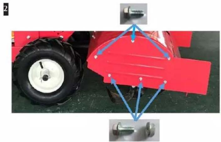
natural_image
Red tractor with tire and mechanical components, no visible text or symbolstext_image
Technical diagram showing a mechanical assembly with labeled parts A, B, and C, including a curved component and a rod-like structure.text_image
Technical diagram showing a U-shaped mechanical component with labeled parts A, B, C, D and a close-up view of a mechanical assembly.A Écrous de blocage
natural_image
Close-up of a black industrial pump with attached lever and mounting bracket, showing red arrows indicating motion or adjustment (no text or symbols visible)natural_image
Metal cage with two circular components and red arrows indicating flow or movement (no text or symbols)text_image
Technical diagram showing a U-shaped mechanical component with labeled parts A, B, C, D and a close-up of its internal structure.A Écrous
text_image
Technical diagram of a mechanical assembly with labeled parts A, B, and CA Broche parallèle
Directive Machines 2010/26/CE
Directive CEM 2014/30/UE
natural_image
Orange and black utility tiller with visible mechanical components (no text or symbols)natural_image
Orange stylized graphic of a running figure next to a turtle on dark background (no text or symbols)
text_image
CHOKE ← LAUF AUS ← EINFILTRO DELL'ARIA
text_image
Labeled diagram of a manual lawn mower with numbered parts for identificationnatural_image
Close-up of a red tire with mechanical components and a small cylindrical component (no visible text or symbols)2

natural_image
Close-up of a red industrial tire with metal clamps and a central circular component (no visible text or symbols)natural_image
Close-up of an orange agricultural tiller with black blades and a large tire, parked on a concrete floor (no visible text or symbols)
natural_image
Close-up of a mechanical tool with a red arrow pointing to a cylindrical component, alongside two metal tools (no text or symbols visible)natural_image
Red surface with yellow arrows pointing to small circular features (no text or symbols)