
VTX V25 - Loudspeaker JBL - Free user manual and instructions
Find the device manual for free VTX V25 JBL in PDF.
| Product type | Professional line array speaker |
| Brand | JBL |
| Model | VTX V25 |
| Dimensions (H x L x P) | 376 mm x 700 mm x 475 mm |
| Weight | 37 kg |
| Power supply | Passive (requires external amplifier) |
| Rated power (RMS) | 1200 W |
| Frequency response | 60 Hz – 20 kHz |
| Impedance | 8 ohms |
| Sensitivity (1W/1m) | 100 dB SPL |
| Main functions | Professional sound reproduction for concerts and events |
| Maintenance and cleaning | Clean with a dry cloth, avoid moisture |
| Safety | Use a suitable stand, do not exceed the rated load |
| Spare parts and repairability | Contact an authorized JBL service center for any repair |
| General information | Rugged speaker designed for touring use |
Frequently Asked Questions - VTX V25 JBL
User questions about VTX V25 JBL
0 question about this device. Answer the ones you know or ask your own.
Ask a new question about this device
Download the instructions for your Loudspeaker in PDF format for free! Find your manual VTX V25 - JBL and take your electronic device back in hand. On this page are published all the documents necessary for the use of your device. VTX V25 by JBL.
USER MANUAL VTX V25 JBL
Before installing hoist, fill in the information below.
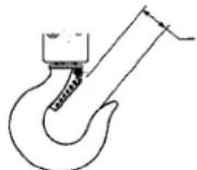
natural_image
Mechanical handcrum with chain and hook attachment (no visible text or symbols)Rated Loads:
3/4, 1, 1 12 , 2, 3 and 6 ton (750, 1000, 1500, 2000, 3,000 and 6,000 kg.)
Follow all instructions and warnings for inspecting, maintaining and operating this hoist.
The use of any hoist presents some risk of personal injury or property damage. That risk is greatly increased if proper instructions and warnings are not followed. Before using this hoist, each operator should become thoroughly familiar with all warnings, instructions and recommendations in this manual. Retain this manual for future reference and use.
Forward this manual to operator. Failure to operate equipment as directed in manual may cause injury.
Capacidades de Carga:
3/4, 1,1½, 2, 3 y 6 toneladas (750, 1000, 1500, 2000, 3000 y 6000 kg.)
Note: When ordering parts, always furnish rated load and serial number of hoist on which the parts are to be used.
To quickly obtain the name of the Master Parts Depot or Service Center located nearest you, call (800) 888-0985. Fax: (716) 689-5644.
LIMITATION OF WARRANTIES, REMEDIES AND DAMAGES
THE WARRANTY STATED BELOW IS GIVEN IN PLACE OF ALL OTHER WARRANTIES, EXPRESS OR IMPLIES, OF MERCHANTABILITY, FITNESS FOR A PARTICULAR PURPOSE, OR OTHERWISE, NO PROMISE OR AFFIRMATION OF FACT MADE BY ANY AGENT OR REPRESENTATIVE OF SELLER SHALL CONSTITUTE A WARRANTY BY SELLER OR GIVE RISE TO ANY LIABILITY OR OBLIGATION.
Seller warrants that on the date of delivery to carrier the goods are free from defects in workmanship and materials.
SELLER'S SOLE OBLIGATION IN THE EVENT OF BREACH OF WARRANTY OR CONTRACT OR FOR NEGLIGENCE OR OTHERWISE WITH RESPECT TO GOODS SOLD SHALL BE EXCLUSIVELY LIMITED TO REPAIR OR REPLACEMENT, F.O.B. SELLER'S POINT OF SHIPMENT, OF ANY PARTS WHICH SELLER DETERMINES TO HAVE BEEN DEFECTIVE or if Seller determines that such repair or replacement is not feasible, to a refund of the purchase price upon return of the goods to Seller.
Any action against Seller for breach of warranty, negligence or otherwise, must be commenced within one year after such cause of action occurs.
NO CLAIM AGAINST SELLER FOR ANY DEFECT IN THE GOODS SHALL BE VALID OR ENFORCEABLE UNLESS BUYER'S WRITTEN NOTICE THEREOF IS RECEIVED BY SELLER WITHIN ONE YEAR FROM THE DATE OF SHIPMENT.
Seller shall not be liable for any damage, injury or loss arising out of the use of the goods, if, prior to such damage, injury or loss, such goods are (1) damaged or misused following Seller's delivery to carrier; (2) not maintained, inspected, or used in compliance with applicable law and Seller's written instructions and recommendations; or (3) installed, repaired, altered or modified without compliance with such law, Instructions or recommendations. UNDER NO CIRCUMSTANCES SHALL SELLER BE LIABLE FOR INCIDENTAL OR CONSEQUENTIAL DAMAGES AS THOSE TERMS ARE DEFINED IN SECTION 2-715 OF THE UNIFORM COMMERCIAL CODE.
Buyer shall comply with and require its employees to comply with directions set forth in Instructions and manuals furnished by Seller and shall use and require its employees to follow such instructions and manuals and to use reasonable care in the use and maintenance of the goods. Buyer shall not remove or permit anyone to remove any warning or instruction signs on the goods. In the event of personal injury or damage to property or business arising from the use of the goods, Buyer shall within 48 hours thereafter give Seller written notice of such injury or damage. Buyer shall cooperate with Seller in investigating any such injury or damage and in the defense of any claims arising therefrom.
If Buyer fails to comply with this section or if any injury or damage is caused, in whole or in part, by Buyer's failure to comply with applicable federal or state safety requirements, Buyer shall indemnify and hold Seller harmless against any claims, loss or expense for injury or damage arising from the use of the goods.
As a CM Hoist and Trolley user you are assured of reliable repair and parts services through a network of Master Parts Depots and Service Centers that are strategically located in the United States and Canada. These facilities have been selected on the basis of their demonstrated ability to handle all parts and repair requirements promptly and efficiently. To quickly obtain the name of the Master Parts Depot or Service Center located nearest you, call (800) 888-0985. Fax: (716) 689-5644.
Improper operation of a hoist can create a potentially hazardous situation which, if not avoided, could result in death, or serious injury. To avoid such a potentially hazardous situation, the operator shall:
- NOT operate a malfunctioning or unusually performing hoist.
- NOT operate the hoist until you have thoroughly read and understood this manual.
- NOT operate a hoist which has been modified without the manufacturer's approval or certification to be in conformity with applicable OSHA regulations.
- NOT lift or pull more than rated load for the hoist.
- NOT use damaged hoist or hoist that is Not working properly.
- NOT use hoist with twisted, kinked, damaged, or worn load chain.
- NOT operate with any lever extension (cheater bar).
- NOT attempt to "free chain" the hoist while a load is applied.
- NOT use the hoist to lift, support, or transport people.
- NOT lift loads over people and make sure all personnel remain clear of supported load.
- NOT attempt to lengthen the load chain or repair damaged load chain.
- Protect the hoists load chain from weld splatter or other damaging contaminants.
- NOT operate a hoist when it is restricted from forming a straight line from hook to hook in the direction of loading.
- NOT use load chain as a sling or wrap load chain around load.
- NOT apply the load to the tip of the hook or to the hook latch.
- NOT apply load unless load chain is properly seated in the chain wheel(s) or sproket(s).
- NOT apply load if bearing prevents equal loading on all load supporting chains.
- NOT operate beyond the limits of the load chain travel.
- NOT leave load supported by the hoist unattended unless specific precautions have been taken.
- NOT allow the chain or hook to be used as an electrical or welding ground.
- NOT allow the chain or hook to be touched by a live welding electrode.
- NOT remove or obscure the warnings on the hoist.
- NOT operate a hoist which has Not been securely attached to a suitable support.
- NOT operate a hoist unless load slings or other approved single attachments are properly sized and seated in the hook saddle.
- NOT lift loads that are Not balanced and the holding action is Not secure, taking up slack carefully.
- NOT operate a hoist unless all persons are and remain clear of the supported load.
- Report malfunctions or unusual performances of a hoist, after it has been shut down until repaired.
- NOT operate a hoist on which the safety placards or decals are missing or illegible.
- Be familiar with operating controls, procedures and warnings.
CAUTION
Improper operation of a hoist can create a potentially hazardous situation which, if not avoided, could result in minor or moderate injury. To avoid such a potentially hazardous situation, the operator shall:
- Maintain a firm footing or be otherwise secured when operating the hoist.
- Check brake function by tensioning the hoist prior to each lift or pulling operation.
- Use hook latches. Latches are to retain slings, chains, etc. under slack conditions only.
- Make sure the hook latches are closed and not supporting any parts of the load.
- Make sure the load is free to move and will clear all obstructions.
- Avoid swinging the load or hook.
- Avoid lever "fly-back" by keeping a firm grip on the lever until operating stroke is completed and lever is at rest.
- Inspect the hoist regularly, replace damaged or worn parts, and keep appropriate records of maintenance.
- Use Columbus McKinnon parts when repairing the unit.
- Lubricate load chain as recommended in this manual.
- NOT operate except with manual power.
- NOT permit more than one operator to pull on lever at the same time. More than one operator is likely to cause hoist overload.
- NOT allow your attention to be diverted from operating the hoist.
- NOT allow the hoist to be subjected to sharp contact with other hoists, structures, or objects through misuse.
- NOT adjust or repair the hoist unless qualified to perform such adjustments or repairs.
The hoists are intended for general industrial use for moving loads within their load ratings. Prior to installation and operation, the user should review the application for abnormal environmental or handling conditions.
GENERAL SAFETY INFORMATION
ADVERSE ENVIRONMENTAL CONDITIONS
Do not use the hoists in areas containing flammable vapors, liquids, gasses or any combustible dust or fibers. Do not use the hoist in highly corrosive, abrasive, wet environments or in applications involving exposure to temperatures below -10 or above 130°F.
MOVING HAZARDOUS LOADS
The hoists are not recommended for lifting materials that could cause widespread damage if dropped. The lifting or moving of materials that could explode or cause chemical or radioactive contamination requires fail-safe, redundant supporting devices that are not incorporated into these hoists.
Description
Series 653 Hand Operated Lever Hoists are highly versatile tools that can be used in any position to efficiently pull, lift, drag or stretch. The frame, covers and lever are made from steel stampings. The gears are heat treated steel, upper and lower hooks are forged steel and the chain is heat treated, welded link type.
Hoist with load ratings of 3/4, 1, 1½, 2 and 3 ton are available and this manual applies to all of these units. The hoists are available with 5, 10, 15 and 20 foot long chains.
Hooks with latches are standard on all units.
Series 653 Hand Operated Lever Hoists are built in accordance with the specification contained herein and at the time of manufacture complies with the applicable sections of the American Society of Mechanical Engineers (ASME) Standard B30.21: Manually Operated Lever Hoists.
Specifications
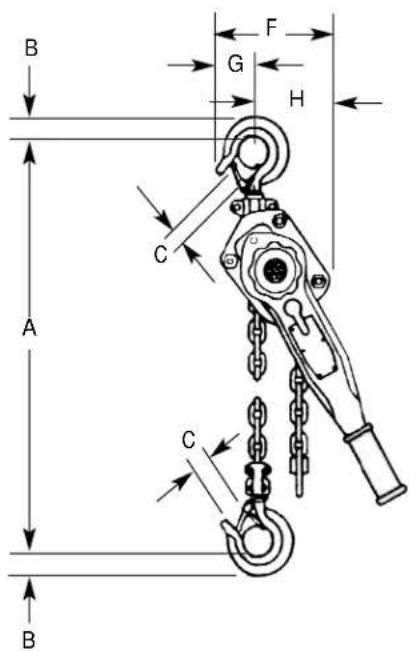
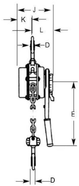
Figure 2 - Specifications
| Model No. | Load Rating (Tons.) | Lift or Reach (Ft.) | Lever pull To Lift Rated Load (Lbs) | Net Weight (Lbs)A B C D | Dimensions (in.) | ||||||||||
| E F G H | J K L | ||||||||||||||
| 5310 | 5 | 15.0 | |||||||||||||
| 5311 | 10 | 15.8 | |||||||||||||
| 5312 | 3/4 | 15 | 33 | 16.6 | |||||||||||
| 5313 | 20 | 17.3 | |||||||||||||
| 5328 | 1 5 44 | 15.0 | 12^5/_8 | 5^1/_16 | 1^1/_8 | 1^1/_16 | 11 | 4^3/_8 | 2^3/_16 | 2^3/_16 | 5^15/_16 | 2^3/_8 | 3^9/_16 | ||
| 5315 | 5 | 27.0 | |||||||||||||
| 5316 | 1^1/_2 | 10 | 51 | 31.4 | |||||||||||
| 5317 | 15 | 35.8 | |||||||||||||
| 5318 | 20 | 40.2 | |||||||||||||
| 5329 2 | 5 | 68 | 27.0 | 14^13/_16 | 1^1/_8 | 1^3/_8 | 1^3/_16 | 16^1/_4 | 4^3/_4 | 2^3/_8 | 2^3/_8 | 6^7/_8 | 3 | 3^15/_16 | |
| 5320 | 3 | 5 | 77 | 45.0 | |||||||||||
| 5321 | 10 | 52.3 | 18^11/_16 | 1^11/_16 | 1^9/_16 | 1^1/_4 | 16^1/_4 | 7^1/_2 | 3^3/_8 | 4^3/_16 | 7^7/_8 | 3^3/_8 | 4^9/_16 | ||
| 5330 | 5 | 78.0 | |||||||||||||
| 5331 | 6 | 10 | 77 | 94.0 | |||||||||||
| 5332 | 15 | 110.0 | 23^1/_4 | 1^13/_16 | 2^3/_16 | 1^1/_2 | 16^1/_4 | 7^1/_2 | 3^3/_8 | 4^3/_16 | 7^7/_8 | 3^3/_8 | 4^9/_16 | ||
| 5333 | 20 | 126.0 | |||||||||||||
Unpacking
After unpacking the hoist, inspect carefully for any damage that may have occurred during transit. Check for loose, missing or damaged parts. Shipping damage claims must be filed with carrier. The hoist is supplied completely assembled and ready to use.
CM® REPAIR/REPLACEMENT POLICY
All Columbus McKinnon (CM ^® ) Series 653 Hoists are inspected and performance tested prior to shipment. If any properly maintained hoist develops a performance problem, within one year of shipment, due to a material or workmanship defect, as verified by CM ^® , repair or replacement of the unit will be made to the original purchaser without charge. This repair/replacement policy applies only to CM ^® Series 653 Hoists installed, maintained and operated as outlined in this manual, and specifically excludes hoists subject to normal wear, abuse, improper installation, improper or inadequate maintenance, hostile environmental effects and unauthorized repairs/modifications.
We reserve the right to change materials or design if, in our opinion, such changes will improve our product. Abuse, repair by an unauthorized person, or use of non-CM ^® replacement parts voids the guarantee and could lead to dangerous operation. For full Terms of Sale, see Sales Order Acknowledgement. Also, refer to the back cover for Limitations of Warranties, Remedies and Damages, and Indemnification and Safe Operation.
Installation
Before installing the hoist:
-
Estimate the weight of the load that is to be lifted or moved and make sure it does not exceed the rated load of the hoist.
-
Make sure the support or sling to which the upper hook is attached is strong enough to hold several times the weight of the load to be lifted or moved. Be sure the hoist is solidly held in the uppermost part of the upper hook and the latch is closed and not in contact with the support or sling.
-
The area in which the hoist is installed must provide sufficient room for:
-The operator to operate the lever. -The operator and other personnel to stand clear of the load at all times.
-Firm footing for the operator.
natural_image
Cartoon illustration of two figures in a crossed fist and arm, symbolizing resistance or aggression (no text or symbols present)-Clearance between the hoist frame and any object. The frame must be free to swivel on the upper hook.
AWARNING
Attaching the hoist from an inadequate support may allow the hoist and load to fall and cause injury and/or property damage.
TO AVOID INJURY:
Make sure the structure has sufficient strength to hold several times the hoist weight and its rated load.
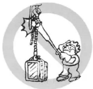
natural_image
Cartoon illustration of a person using a crane to lift a large object, no text or symbols presentOperation
AWARNING
If not used as directed, lever hoist may cause injury.
TO AVOID INJURY:
Use only as directed below. Read all instructions before operating the Series 653 Hand Operated Lever Hoist.
GENERAL
- The hoist must be kept clean to assure proper operation. Before use, check to be sure the load chain is clean, that there is no foreign material in the liftwheel area and that the lever operates freely.
- Do not load beyond the rated capacity. Overload can cause immediate failure or cause damage resulting in future failure, even at less than rated capacity.
- Do not use this hoist or any other material handling equipment for lifting or moving people, or lifting loads over people.
- Stand clear of all loads and warn other people of your intention to move a load in their area.
- Do not leave a load on the unit unattended.
- Read warnings and instructions on the hoist before each use.
- Do not hold the load chain while operating the hoist. Should the hoist not operate properly, serious injury may occur.
- Never operate the hoist when flammable materials or vapors are present. Contact between metal parts may produce sparks that can cause a fire or explosion.
- STAY ALERT! Watch what you are doing and use common sense. Do not use the hoist when you are tired, distracted or under the influence of drugs, alcohol or medication causing diminished control.
AWARNING
Malfunction of unit, rigging slip or loss of footing may cause user to slip resulting in injury.
TO AVOID INJURY:
Always have a firm and secure footing when using the Series 653 Hand Operated Lever Hoist.
FREE CHAINING
In this mode of operation, the chain can be pulled through the hoist in either direction by hand for quick attachment to the load.
To engage the free chaining feature, remove any load from the hoist and move the directional lever to the ("N") position.
Operation (Continued)
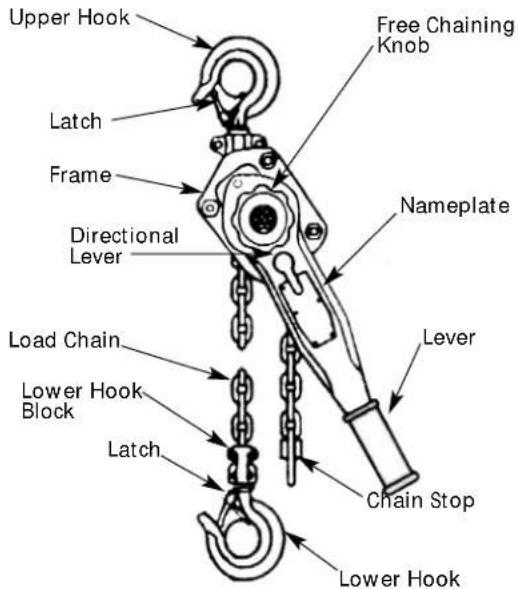
Figure 3 - Main Parts of Lever Hoist
Turn the free chaining knob counterclockwise (♂) to disengage the brake and pull on either chain until the lower hook is at the desired position. To disengage the free chaining feature, move the directional lever to the load (↑) or unload position (↓). Pull the load chain in either direction to insure the unit is out of the free chaining mode.
Do not take up the load chain to the point where the chain stop or lower hook block becomes jammed against the frame.
ATTACHING THE LOAD
Attach the lower hook to the load so that it is seated in the bowl of the hook and is not bearing against the tip of the hook or latch, and the latch is tight against the hook tip.
AWARNING
Allowing the load to bear against the hook latch and/or hook tip can result in loss of load.
TO AVOID INJURY:
Do not allow the load to bear against the hook latch and/or hook tip. Apply load to hook bowl or saddle only.
Do not wrap the chain around the load and hook onto itself as a choker chain sling or bring the load in contact with the hoist. Doing this will result in the loss of the swivel effect of the hook which could cause twisted chain and a jammed liftwheel. Also, the chain may be damaged at the hook. Make sure the upper and lower hooks are in a straight line and the frame is free to swivel on the upper hook.
AWARNING
If the unit is not rigged in a straight line hook to hook manner, and if the frame is not free to swivel, lever pull may break frame and cause physical injury and loss of load.
TO AVOID INJURY:
Rig the unit in a straight line hook to hook manner and keep frame free to swivel (See Figure 4).
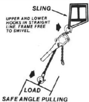
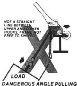
Figure 4 - Pulling at an Angle
TO PULL OR LIFT LOAD
Move directional lever to load (↑) position. Operate lever in up and down motion to shorten the distance between hooks and thus pull or lift the load.
When pulling or lifting move the load only enough to slightly load the unit, then check to be sure that the attachments to the hooks and load are firmly seated. Continue movement only after you are assured the load is free of all obstructions.
The hoist has been designed for hand powered operation only. Do not use an extension on the lever. Lever pulls of 33 pounds on 3/4 ton unit, 44 pounds on 1 ton unit, 51 pounds on 1½ ton unit, 68 pounds on 2 ton unit and 77 pounds on the 3 and 6 ton unit will result in rated capacity on the unit. Any greater pull is an indication of either an overload or an incorrectly maintained unit.
AWARNING
Power operation may cause structural damage or premature wear that in turn may cause a part to break and allow the load to fall.
TO AVOID INJURY:
Operate the Series 653 Lever Hoist using hand power only!
TO LOOSEN OR LOWER LOAD
Move directional lever to unload (↓) position. Again, operate lever in an up and down motion to increase the distance between hooks and thus loosen or lower the load.
LOCKED BRAKE
If a hoist which is under load is suddenly relieved of the load by lifting the load off of the lower hook by some other means or pulling down walls, the brake will lock.
The brake will also lock if the lower hook block is pulled tightly against the frame.
To unlock the brake, turn the directional lever to the unload (↓) position and pull on the lever sharply.
AWARNING
Turning the Free Chaining Knob with a load attached will allow the load to release and may cause injury.
TO AVOID INJURY:
Never turn the Free Chaining Knob when the lever hoist is under load.
INSPECT HOIST
Before each use and at specified intervals as directed in the inspection section.
AWARNING
Use as directed above. Failure to do so may cause injury to you or others.
- DO NOT exceed capacity shown on nameplate.
- DO NOT use to lift people or loads over people.
- DO NOT use unless the hoist's frame and chain form a straight line between hooks.
- DO NOT use if the frame is in contact with any object.
- DO NOT use if the unit is damaged or malfunctions.
- DO NOT use extension on lever. Use hand power only.
- DO NOT use if chain is twisted, kinked or damaged.
Maintenance
INSPECTION
To maintain continuous and satisfactory operation, a regular inspection procedure must be initiated so that worn or damaged parts can be replaced before they become unsafe. The intervals of inspection must be determined by the individual application and are based upon the type of service to which the hoist is subjected. The intervals indicated as follows are based on normal service.
The inspections are divided into two general classifications designated as "frequent" and "periodic".
FREQUENT INSPECTIONS
These inspections are usually visual examinations by the operator. Frequent inspections are to be performed daily or before each use and they are to include:
-
Braking mechanism for evidence of slippage.
-
Operation of the directional lever for free movement.
-
Load chain for lubricant, wear, damaged links or foreign material.
-
Hooks for damage, cracks, twists, latch engagement and latch operation.
PERIODIC INSPECTIONS
These are visual inspections of external and internal conditions by a designated person making records to provide the basis for continuing evaluation of the condition of the hoist. The periodic inspection should include those items listed under frequent inspection as well as the following:
- Chain for excessive wear or stretch (See Figures 6 and 7, page 6) - every three months.
- Worn, cracked or distorted parts such as lower hook block, upper hook block, upper hook pin, chain guide rollers, bushings, lever, brake cover, free chaining knob, directional pawl, friction hub and lever ratchet - every three months.
- Inspect for wear on the tip of the pawls, teeth of the ratchet, and pockets of the liftwheel - every three months.
-
Loose or missing bolts, nuts, pins or rivets - every three months.
-
Inspect the brake components for worn, glazed or contaminated friction discs and scoring of the friction hub and ratchet. Replace friction washers if contaminated, glazed or if thickness is less than 0.094 in. (2.4 mm) - every three months.
-
Corroded, stretched or broken pawl springs, directional lever pawl spring and lever ratchet spring - every three months.
-
Hooks - dye penetrant, magnetic particle or other suitable crack detecting inspection should be performed at least once a year, if external conditions indicate there has been unusual usage.
-
Nameplate and Warning Labels for legibility and retention-every three months.
-
Chain stop in place and properly secured - every three months.
Any deficiency should be corrected before the hoist is returned to service. Also, the external conditions may show the need for more detailed inspection which, in turn, may require the use of non-destructive type testing.
Any parts deemed unserviceable are to be replaced with new parts before the hoist is returned to service. It is very important that the unserviceable parts are destroyed and properly disposed of to prevent their possible future use as a repair item.
When the unit is subjected to heavy usage or dusty, gritty, moist or corrosive atmospheric conditions, shorter time periods must be assigned. Inspection must be made of all parts for unusual wear, corrosion or damage, in addition to those specifically mentioned in the schedule.
HOOK INSPECTION
Hooks damaged from chemicals, deformations or cracks, or that have more than a 10^ twist from the plane of the unbent hook, excessive opening or seat wear, must be replaced. Also, hooks that are opened to the extent that the latch does not engage the tip must be replaced. Any hook that is twisted or has excessive throat opening indicates abuse or overloading of the hoist. Other load sustaining parts should be inspected for damage.
Depress latch to measure throat opening
Figure 5 - Hook Inspection
| Hoist Replace Hook When | |
| Capacity(Tons) | Opening is Greater Than: (in.) |
| 3/4 1 4 | |
| 1 | 1 4 |
| 112 | 1^3/_8 |
| 2 | 112 |
| 3 | 1^23/_3 |
| 6 | 2^5/_16 |
Check to assure the latch is not damaged or bent and that it operates properly. It should have sufficient spring pressure to keep it tightly against the tip of the hook and allow it to spring back to the tip when released. If the latch does not operate properly, replace the latch.
The chart above should be used to determine when the hook must be replaced.
LOAD CHAIN
Chain should feed smoothly into and away from the hoist. If chain binds, jumps or is noisy, first clean and lubricate it (See Page 6). If trouble persists, inspect chain and mating parts for wear, distortion or other damage.
Maintenance (Continued)
CHAIN INSPECTION
First clean chain with a non-caustic/ non-acid type solvent and make a link by link inspection for nicks, gouges, twisted links, weld spatter, corrosion pits, sitiations (minute parallel lines), cracks in weld areas, wear and stretching. Chain with any one of these defects must be replaced.
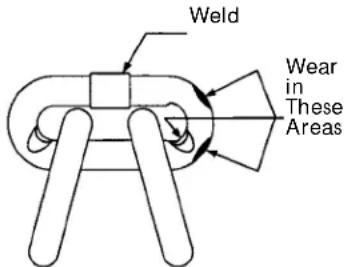
Figure 6 - Chain Inspection
Slack the portion of the chain that normally passes over the liftwheel. Examine the interlink area for the point of maximum wear (polishing). Measure and record the stock diameter at this point of the link. Then measure stock diameter in the same area on the link that does not pass over the liftwheel (use the link adjacent to the chain stop for this purpose). Compare these two measurements. If the stock diameter of the worn link is 0.010 inches (0.254mm), or more, less than the stock diameter of the unworn link, the chain must bereplaced.
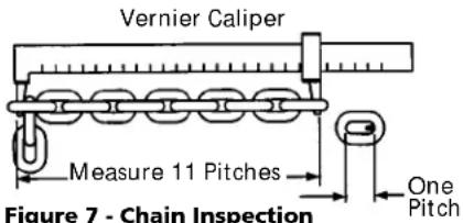
Also check chain for stretch using a vernier caliper as shown in Figure 7. Select an unused, unstretched section of chain (usually at the loose end) and measure and record the length over 11 chain links (pitches). Measure and record the same length on a worn section of chain.
If the result (amount of stretch and wear) is greater than 0.145 inch (3.7 mm), the chain must be replaced.
Use only a "Knife-Edge" caliper to eliminate possibility of false reading by not measuring full pitch length.
AWARNING
Using other than Series 653 supplied load chain may cause the chain to jam in the hoist and/or allow the chain to break and the load to drop.
TO AVOID INJURY:
Due to size requirements and physical properties, use only Series 653 supplied load chain in the Series 653 Lever Hoist.
Note that worn chain can be an indication of worn hoist components. For this reason, the hoist's frame, stripper, and liftwheel should be examined for wear and replaced as necessary when replacing worn chain (See DISASSEMBLY and ASSEMBLY below).
Also, the load chain is specially heat treated and hardened and should never be repaired.
IMPORTANT: Do not use replaced chain for other purposes such as lifting or pulling. Load chain may break suddenly without visual deformation. For this reason, cut replaced chain into short lengths to prevent use after disposal.
CHAIN LUBRICATION
A small amount of lubricant will greatly increase the life of load chain. Do not allow the chain to run dry. Keep it clean and lubricate at regular intervals with Lubriplate® Bar and Chain Oil 10-R (Fiske Bros. Refining Co.) or equal lubricant. Normally, weekly lubrication and cleaning is satisfactory, but under hot and dirty conditions, it may be necessary to clean the chain at least once a day and lubricate it several times between cleanings.
When lubricating the chain, apply sufficient lubricant to obtain natural run-off and full coverage, especially in the interlink area.
AWARNING
Used motor oils contain known carcinogenic materials.
TO AVOID INJURY:
Never use used motor oils as a chain lubricant. Only use Lubriplate® Bar and Chain Oil 10-R as a lubricant for the load chain.
Hoist normally requires no additional lubrication except when it had been disassembled for cleaning or repairs.
IMPORTANT: Brake is designed to operate dry. Do not use any grease or lubricant on the braking surfaces.
When lubricating parts adjacent to the brake, do not use an excessive amount of lubricant which could seep onto the brake surfaces.
AWARNING
Using any grease or lubricant on the braking surfaces will cause brake slippage and loss of load control which may result in injury and/or property damage.
TO AVOID INJURY:
Do not use any grease or lubricant on braking surfaces. The brake is designed to operate dry.
When the hoist is disassembled for cleaning or repairs, the following locations should be lubricated with approximately 1 oz. per hoist of Molykote BR-2-S (Dow Corning), Molytex #2 (Texaco) or TopMoly (Topsall) grease or equal lubricant: gears, rollers of the liftwheel bearing, exterior of pinion shaft, surfaces of frame bushings and surface of gear cover bushings. Be sure to thoroughly clean the old grease from these parts before re-lubricating.
IMPORTANT: To insure long life and top performance, be sure to lubricate the various parts of the hoist using the lubricants specified above. If desired, these lubricants can be purchased from Columbus McKinnon (See Figure 13, page 8).
DISASSEMBLY AND ASSEMBLY
The parts illustration and list on pages 12 and 13 show the general arrangement and name of the parts of the Series 653 Lever Hoist. These should be used when disassembling and re-assembling the units so that all parts are properly installed.
DISASSEMBLY
Points of caution to be observed upon disassembly of the hoist are:
- Loose rollers are used for the liftwheel bearing, (refer to parts list for number required). Care must be taken so as to not loose or misplace these rollers since they may drop from the unit as the various parts are disassembled.
Maintenance (Continued)
- To replace the liftwheel or stripper, completely disassemble the unit: remove the chain (See REPLACING LOAD CHAIN, page 7) and then remove the brake nut, cotter pin and spacer (19), free chaining knob (17), lever (16), check washer (18), lever ratchet (33), brake cover (14), friction discs (12), ratchet (13), spring (6) and friction hub (11). On the gear side, remove the gear cover (8), gears (5) and pinion (7). Remove snap ring and liftwheel gear (23). Being careful not to loose the rollers, remove the side plate assembly (1). Slide the liftwheel (22) out of the side plate (2), being careful not to loose the rollers. The stripper (4) can also be removed now.
Prior to re-assembly, check all parts for excessive wear, cracks and distortion. Replace parts as necessary and then re-assemble the unit in reverse to the order given above, making sure to install the chain guide rollers (10) and upper hook (25) and pin (26). After assembly, install the chain (See REPLACING LOAD CHAIN, page 7) and then test the unit (See TESTING, page 8).
- The latch is secured to the hook (upper and lower) by a rivet. To remove the latch, it is necessary to remove the head of the rivet by grinding or drilling. For the replacement of the latch, refer to the paragraphs under assembly instructions.
ASSEMBLY:
- Thread the friction hub (11) onto the pinion shaft (7) and assemble the friction discs and the ratchet on the friction hub (See Figure 8).
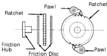
Figure 8 - Brake Assembly
Place the spring (6) over the friction hub and pinion. Place the brake cover assembly (14) on the frame and thread the lever ratchet (33) onto the pinion shaft. Firmly seat the lever ratchet and secure the brake cover assembly to the frame using the four nuts (9).
Place the check washer (18) on the pinion shaft so that there is 0.094 to 0.312 inches (2 to 8 mm) between the edge of the check washer and the raised stop on the lever ratchet hub (See Figure 9).
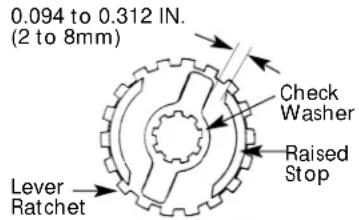
Figure 9 - Position of Check Washer
Make sure the directional lever is in the neutral ("N") position and the pawl, spring and shaft (20) are in the lever assembly (16), attach the lever assembly to the brake cover (14) using the two locknuts, screw and lockwasher (15). Place the free chaining knob (17) on the lever ratchet hub (33). Place the spacer (19) over the pinion shaft, thread the brake nut (19) onto the pinion shaft, and firmly tighten the nut. Back off the nut one to two flats and insert the cotter pin (19). Bend the legs of the cotter pin to secure.
-
When assembling the latch to the hook, the end of the rivet must be peened over. When peening over rivet, only apply enough force to form a head to retain the pin. Excessive force will deform the latch and make the latch inoperable.
-
When assembling the gears, they must be orientated with the timing marks aligned (See Figure 10).
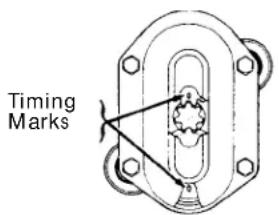
Figure 10 - Gear Timing
REPLACING LOAD CHAIN
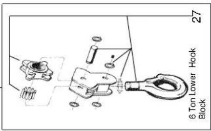
To replace the load chain, remove the lower hook block and chain stop from the chain. Move the directional lever to the neutral "N" and pull the old chain out of the hoist. Feed a length of soft wire through one side of the chain guide roller and over the liftwheel until it comes out on the other side of the chain guide roller. Attach the wire to the end of the new chain. Position the chain so that the first link to enter the chain guide roller will be an upstanding link and the welds on all upstanding links will be away from the liftwheel. Pull on the wire until the chain engages the liftwheel. Turn the free chaining knob, while pulling on the wire, until the chain comes out of the chain guide roller. Pull the chain through and remove the wire. On the 3/4, 1, 1 1/2, 2
and 3 Ton units attach the lower hook block to the chain that is directly below the upper hook. On the 6 Ton unit, reeve the chain as shown below. Attach the chain stop to the other end of the chain.
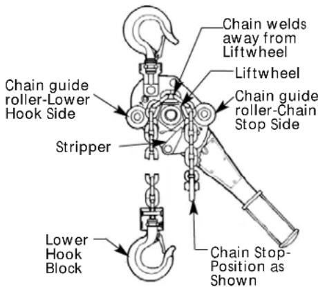
Chain Installation-3/4, 1, 1½, 2 and 3 Ton
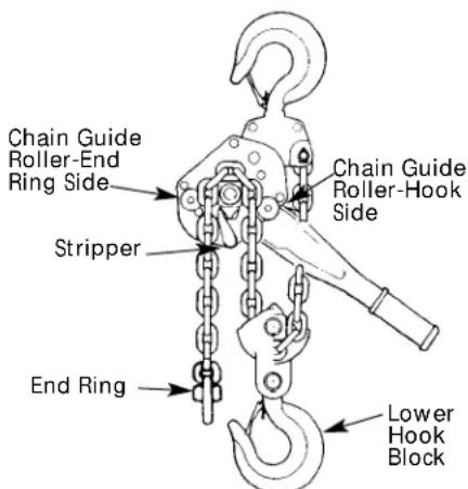
Figure 11. Reeving - 6 Ton
AWARNING
Alterations or modifications of equipment and use of any parts other than Series 653 repair parts can lead to dangerous operation and injury.
TO AVOID INJURY:
Do not alter or modify equipment. Do use only Series 653 provided replacement parts.
RECOMMENDED SPARE PARTS
To insure continued operation, it is recommended that two friction discs (12) for each Series 653 lever hoist in service, be kept on hand at all times to replace friction washers that are worn, contaminated or glazed.
Maintenance (Continued)
PREVENTATIVE MAINTENANCE
In addition to the inspection procedures, a preventative maintenance program should be established to prolong the useful life of the hoist and maintain its dependability and continued safe use. The program should include the periodic inspections with particular attention being paid to the lubrication of various components using the recommended lubricants (See Figure 13).
TESTING
Prior to initial use, all repaired or used hoists that have not been operated for the previous 12 months shall be tested by the user for proper operation.
Test the unit first in the unloaded state and then with a light load of 100 pounds (45 kg.) times the number of load supporting parts of load chains to be sure it operates properly and the brake holds the load when the lever is released; then test with a load of 125% of rated capacity.
In addition, hoists in which load sustaining parts have been replaced must be tested with 125% of rated capacity by or under the direction of a designated person and a written report prepared for record purposes.
NOTE: For additional information on Inspection and Testing refer to ASME B30.21 "Manually Lever Operated Hoists" obtainable from ASME Order Department, 22 Law Drive, Box 2300, Fairfield, NJ 07007-2300, U.S.A.
| INSPECTOR'S REPORT | |
| ITEM REMARKS (LIST DEFICIENCIES AND RECOMMENDED ACTION) | |
| Inspector's DateSignature Inspected Approved by Date | |
Figure 12 — Recommended Inspector's Report
| RECOMMENDED LUBRICATION SCHEDULE* SERIES 653 HAND OPERATED LEVER HOISTS | ||||||
| REFERENCE NO. COMPONENT TYPE OF LUBRICANT (SEE PAGES 12 & 13) PART NO. FREQUENCY OF LUBRICATION | ORDER TYPE OF SERVICE AND | |||||
| 32 | Load Chain Oil (See Page 6) 28619 | Daily Weekly Monthly (1 gal. can) | HEAVY NORMAL INFREQUENT | |||
| 5, 1, 8, 24 & 7 | Gears, Bushings, Liftwheel rollers & Pinion shaft | Grease (See page 6) | 28618(1 lb. can) | When hoist is disassembled for cleaning or repairs | ||
(*) This lubrication schedule is based on a hoist operating in normal environment conditions. Hoists operating in adverse atmospheres containing excessive heat, corrosive fumes or vapors, abrasive dust, etc., should be lubricated more frequently.
Figure 13 — Recommended Lubrication Schedule
Maintenance (Continued)
| Type of Hoist | Capacity (Tons) |
| Location | Original Installation Date |
| Manufacturer | Manufacturer's Serial No. |
| Item Frequency of Inspection Possible Deficiencies OK | Action | Required | |||
| Brake Mechanism | * * Slippage or excessive drift. | ||||
| Worn, glazed or contaminated friction discs. Thickness of discs less than 0.094 inches. | |||||
| Directional Lever | * * Binding and does not move freely. | ||||
| Load Chain * | damaged or twisted links, corroded or clogged with foreign material. | Inadequate lubrication, excessive wear or stretch, cracked material. | |||
| Hooks | * * Excessive throat opening, twisted more than 10^ , damaged or non-operating hook latch, chemical damage. Cracks (Use dye penetrant, magnetic or other suitable detection method at least once a year). | ||||
| Lower Hook Block, Upper Hook Block, Upper Hook Pin, Chain Guide Rollers, Bushings, Gears, Pinion and Friction Hub | * | Cracks, distortion, excessive wear, corrosion or build-up of foreign material. | |||
| Tip of Pawls and Lever Pawl Teeth of Ratchet and Lever Ratchet | * | Cracks, distortion, excessive wear, corrosion or build-up of foreign material. | |||
| Pockets of Liftwheel, Stripper and Side Plates | * | Cracks, distortion, excessive wear, corrosion or build-up of foreign material. | |||
| Nuts, Bolts, Pins and Rivets | * | Cracks, bending, loose, stripped threads. | |||
| Pawl Springs, Directional Pawl Spring, and Spring | * | Corrosion, stretched or broken. | |||
| Chain Stop | * | Missing, cracked, not secured to chain, not properly positioned. | |||
| Nameplate, Warning Labels and Free Chaining Tags | * | Missing, Damaged or illegible. | |||
| NOTE: Refer to Maintenance and Inspection Sections of this manual for further details. | |||||
FREQUENCY OF INSPECTION
Frequent - Indicates items requiring inspection daily or before each use. These inspections may be performed by the operator if properly designated.
Periodic -- Indicates items requiring inspection every three months. Inspections to be performed by or under the direction of a properly designated person. The exact period of inspection will depend on frequency and type of usage. Determination of this period will be based on the user's experience. It is recommended that the user begin with a quarterly inspection and extend the periods to semi-annually or annually based on the user's quarterly experience.
NOTE: This inspection and maintenance check list is in accordance with our interpretation of the requirements of the Safety Standard for Overhead Hoists ASME B30.16. It is, however, the ultimate responsibility of the employer/user to interpret and adhere to the applicable requirements of this safety standard.
Figure 14 — Recommended Inspection and Maintenance Check List
Troubleshooting Chart
Symptom Possible Cause(s) Corrective Action
| Hoist is hard to operate 1. Load chain worn long to 1. Check chain, (See page 6) and replace if worn in either direction. gauge, thus binding between excessively. liftwheel and chain guide roller.2. Load chain rusty, corroded or 2. Clean chain by tumble polishing or using a clogged with foreign matter non-acid or non-caustic type solvent. Check chain such as cement or mud. for gouges, damaged or bent links. Lubricate with Lubriplate® Bar and Chain Oil 10-R (Fiske Bros. Refining Co.) or equal lubricant.3. Bushings or liftwheel rollers 3. Disassemble and clean liftwheel rollers and clogged with matter such as bushings in gear cover and side plate (gear side). cement or dust. Any parts worn excessively should be replaced.4. Lever binding. 4. Clean by removing any foreign matter which may be between the lever and the brake cover.5. Brake parts corroded or 5. Disassemble broke and clean thoroughly (by wiping clogged with foreign matter. with a cloth - not by washing in a solvent). Replace discs if too gummy, worn or scored. Keep discs and brake surfaces clean and dry.6. Liftwheel pockets clogged with foreign matter or worn excessively causing chain to bind between liftwheel and chain guide rollers.7. Liftwheel twisted or bent - gear teeth bent.8. Check washer not in correct position. | 1. Brake adjusting nut is too tight.2. Brake parts corroded or clogged with foreign matter.3. Chain binding. | 1. See BRAKE ASSEMBLY, page 7.2. Disassemble brake and clean thoroughly (by wiping with a cloth - not by washing in a solvent). Replace discs if too gummy, worn or scored. Keep discs and brake surfaces clean and dry.3. Check chain, (See page 6) and replace if worn excessively. Clean chain by tumble polishing or using a non-acid or non-caustic type solvent. Check chain for gouges, damaged or bent links. Lubricate with Lubriplate® Bar and Chain Oil 10-R (Fiske Bros. Refining Co.) or equal lubricant. |
| Hoist is hard to operate in up direction. | 1. Chain binding.2. Overload. | 1. Check chain, (See page 6) and replace if worn excessively. Clean chain by tumble polishing or using a non-acid or non-caustic type solvent. Check chain for gouges, damaged or bent links. Lubricate with Lubriplate® Bar and Chain Oil 10-R (Fiske Bros. Refining Co.) or equal lubricant.2. Reduce load or use correct capacity unit. |
Notes
Please provide the following information:
-Model number
-Serial number
-Part description and number as shown in parts list
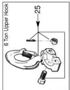
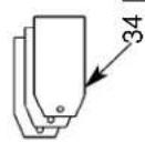
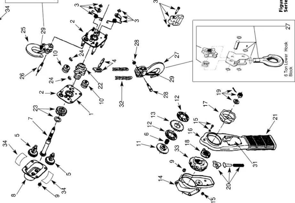
Figure 15 —
Series 653 Hand Operated Lever Hoist
Figure 15 —
Repair Parts List
| Ref.No. | Description | Capacities: | Qty. | |||||
| 3/4T | 1T | 112 T | 2T | 3T | 6T | |||
| 1 Side plate assembly(gear side)-includes2 bushings andbearing race | 53750 | 53750 | 53751 | 53751 | 53752 | 537521 | ||
| 2 Side plate assembly(brake side)-includes2 pawl studs, bearingrace and 4 studs | 53753 | 53753 | 53754 | 53754 | 53755 | 53755 | 1 | |
| 3 Pawl, spring and retainerring | 53756 | 53756 | 53757 | 53757 | 53794 | 537942 | ||
| 4 Stripper 53758 53758 53759 53759 53760 53760 1 | ||||||||
| 5 Gear set (2 gears) | 53761 | 53761 | 53762 | 53762 | 53763 | 537631 | ||
| 6 Spring | 53764 | 53764 | 53765 | 53765 | 53765 | 53765 | 1 | |
| 7 Pinion | 53766 | 53766 | 53767 | 53767 | 53768 | 53768 | 1 | |
| 8 Gear cover with bushings | 53876 | 53876 | 53881 | 53881 | 53885 | 53885 | 1 | |
| 9 Gear and brake coverhardware kit-includes8 nuts | 53772 | 53772 | 53773 | 53773 | 53774 | 53774 | 1 | |
| 10 Chain guide roller | 53775 | 53775 | 53776 | 53776 | 53777 | 53777 | 2 | |
| 11 Friction hub | 53778 | 53778 | 53779 | 53779 | 53780 | 53780 | 1 | |
| 12 Friction disc | 53781 | 53781 | 53782 | 53782 | 53844 | 53844 | 2 | |
| 13 Ratchet | 53783 | 53783 | 53784 | 53784 | 53785 | 53785 | 1 | |
| 14 Brake cover assembly | 53877 | 53877 | 53882 | 53882 | 53886 | 53886 | 1 | |
| 15 Lever hardware kit-includes1 screw, 1 lockwasherand 2 locknuts | 53789 | 53789 | 53790 | 53790 | 53845 | 53845 | 1 | |
| 16 Lever assembly-includesdirectional lever | 53878 | 53878 | 53883 | 53883 | 53887 | 53887 | 1 | |
| 17 Free chaining knob | 53879 | 53879 | 53879 | 53879 | 53879 | 53879 | 1 | |
| 18 Check washer | 53796 | 53796 | 53796 | 53796 | 53796 | 53796 | 1 | |
| 19 Brake nut kit-includes nut,cotter pin and spacer | 53797 | 53797 | 53798 | 53798 | 53846 | 53846 | 1 | |
| 20 Directional pawl kit-includes pawl, springand shaft | 53799 | 53799 | 53800 | 53800 | 53800 | 53800 | 1 | |
| 21 Lever grip | 53801 | 53801 | 53802 | 53802 | 53802 | 53802 | 1 | |
| 22 Liftwheel | 53838 | 53838 | 53839 | 53839 | 53840 | 53840 | 1 | |
ADVERTENCIA
natural_image
Cartoon illustration of two figures in a boxing stance, one striking the other (no text or symbols)natural_image
Cartoon illustration of a person using a crane to lift a box, no text or symbols presentOperación
ADVERTENCIA
natural_image
Cartoon illustration of two figures in a boxing stance, one striking the other (no text or symbols)natural_image
Cartoon illustration of a person using a heavy load device to lift a large box (no text or symbols present)Opération
AVERTISSEMENT
- Rated Loads:
- Capacidades de Carga:
- LIMITATION OF WARRANTIES, REMEDIES AND DAMAGES
- CAUTION
- GENERAL SAFETY INFORMATION
- ADVERSE ENVIRONMENTAL CONDITIONS
- MOVING HAZARDOUS LOADS
- Description
- Specifications
- Unpacking
- CM® REPAIR/REPLACEMENT POLICY
- Installation
- AWARNING
- TO AVOID INJURY:
- Operation
- GENERAL
- FREE CHAINING
- ATTACHING THE LOAD
- TO PULL OR LIFT LOAD
- TO LOOSEN OR LOWER LOAD
- LOCKED BRAKE
- INSPECT HOIST
- Maintenance
- INSPECTION
- FREQUENT INSPECTIONS
- PERIODIC INSPECTIONS
- HOOK INSPECTION
- LOAD CHAIN
- Maintenance (Continued)
- CHAIN INSPECTION
- CHAIN LUBRICATION
- DISASSEMBLY AND ASSEMBLY
- DISASSEMBLY
- ASSEMBLY:
- Figure 10 - Gear Timing
- REPLACING LOAD CHAIN
- RECOMMENDED SPARE PARTS
- PREVENTATIVE MAINTENANCE
- TESTING
- FREQUENCY OF INSPECTION
- Troubleshooting Chart
- Notes
- ADVERTENCIA
- Operación
- Opération
- AVERTISSEMENT
Brand : JBL
Model : VTX V25
Category : Loudspeaker