
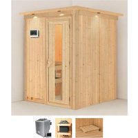
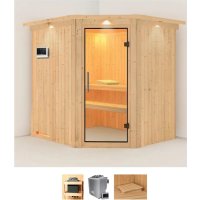
Mia - Sauna Karibu - Free user manual and instructions
Find the device manual for free Mia Karibu in PDF.
| Product type | Sauna control (controller for hybrid stove) |
| Brand | Karibu |
| Model | Mia (Modern Bio) |
| Dimensions (W x H x D) | 238 x 195 x 90 mm |
| Power supply | 400 V three-phase 3N~50 Hz, fixed connection |
| Power consumption (min/max) | 4.3 / 6.3 VA |
| Switching power (heating) | 3 x 3 kW (max. 9 kW), expandable to 18 or 30 kW with module |
| Switching power (evaporator) | 3 kW |
| Switching current per phase | 13 A (heating and evaporator) |
| Temperature range | 40 °C to 125 °C (sauna mode), 40-65 °C (hybrid mode) |
| Humidity range | 0 to 100 % (hybrid mode, limited by temperature) |
| Protection rating | IP X4 (protection against water splashes) |
| Functions | Sauna mode, hybrid mode, programmed operation (delayed start up to 23h45), lighting, optional door monitoring |
| Safety | Safety temperature limiter (139 °C), automatic shutdown after 6 h of heating, dual sensor system |
| Sensors | Stove sensor (with overtemperature limiter) and bench sensor, 3 m cables |
| Lighting | Max. power 100 W, fuse 1 A T |
| Ambient temperature | From -10 °C to +40 °C |
| Max. ambient humidity | 95% |
| Cleaning | Soft cloth and mild soap; do not immerse or spray water |
| Maintenance | No maintenance required |
| Delivery contents | Sauna control, stove sensor, bench sensor, mounting accessories |
| Installation | By a qualified electrician, outside the cabin, at a height of 1.70 m |
Frequently Asked Questions - Mia Karibu
User questions about Mia Karibu
0 question about this device. Answer the ones you know or ask your own.
Ask a new question about this device
Download the instructions for your Sauna in PDF format for free! Find your manual Mia - Karibu and take your electronic device back in hand. On this page are published all the documents necessary for the use of your device. Mia by Karibu.
USER MANUAL Mia Karibu
Sauna and evaporator control unit
Modern Bio
52949

INSTRUCTIONS FOR INSTALLATION AND USE English

EN
Table of Contents
- About this instruction manual 4
- Important information for your safety 5
2.1. Intended use 5
2.2. Safety information for the installer 6
2.3. Safety information for the user 7
- Product description 8
3.1. Scope of delivery 8
3.2. Product functions 8
- Installation and connection 10
4.1. Installing the sauna control unit 11
4.2. Connecting wires 12
4.3. Installing the heater sensor with excess temperature fuse 14
4.4. Installing the bench sensor 16
4.5. Installing a door monitor (optional) 16
4.6. Performing tests 17
- Troubleshooting for the installer 18
- Connection diagram 21
- Operating elements 22
- Meaning of the displays 22
Table of Contents
9. Operation 23
9.1. Switching on the light .23
9.2. Switching on the sauna control unit .23.
9.3. Starting sauna mode – Quick-start 23
9.4. Combi mode - Quick-start 24
9.5. Sauna mode with preset time (starting the time-delay) 24
9.6. Combi mode with preset time (starting the time-delay) 25
9.7. Deleting the preset time .26
9.8. Switching off the sauna control unit 26
9.9. Extended periods of non-use 26
9.10. How the optional door monitor works 26
10. Cleaning and maintenance 28
10.1. Cleaning 28
10.2. Maintenance...28
11. Disposal 28
12. Troubleshooting for users.
12.1. Exceeding the heating period 29
12.2. Light does not operate 29
12.3. Low-water display....29
12.4. Error messages....30
13. Technical data 31
1. About this instruction manual
Read these installation and operating instructions carefully and keep them within reach when using the sauna control unit. This ensures you can refer to information about safety and operation at any time.
These installation and operating instructions can also be found in the downloads section of our website: www.karibu.de.
Symbols used for warnings
These installation and operating instructions feature warning symbols next to activities presenting a hazard to the user. Warning symbols must be observed at all times. This prevents damage to property and injuries, which in the worst case may be fatal.
The warning symbols contain keywords with the following meanings:

DANGER!
Serious or fatal injury will occur if this warning symbol is not observed.
WARNING!
Serious or fatal injury may occur if this warning symbol is not observed.

CAUTION!
Minor injuries may occur if this warning symbol is not observed.
ATTENTION!
This keyword is a warning that damage to property may occur.
Other symbols
This symbol indicates tips and useful information.
2. Important information for your safety
The Modern Bio sauna control unit has been manufactured in accordance with the applicable safety regulations for technical units. However, hazards may occur during use. You should therefore adhere to the following safety information and the specific warnings in the individual chapters.
2.1. Intended use
The Modern Bio sauna control unit is used for operating and regulating sauna heaters in a private household in accordance with the technical data. It may only be used for operating and controlling 3 heating circuits with a maximum heating capacity of 3 kW per heating circuit. The maximum evaporator output is 3 kW.
Any use exceeding this scope is considered improper. Improper use can result in damage to the product, severe injuries or death.
EN
2.2. Safety information for the installer
- Installation may only be performed by a qualified electrician or similarly qualified person.
- Installation and connection of the sauna control unit may only be performed when the power supply is disconnected.
- An all-pole disconnecting device with full cut-off must be fitted on-site in accordance with overvoltage category III.
- The sauna control unit must be installed outside the sauna cabin at a height of approx. 1.70 m, or in accordance with the recommendation given by the sauna manufacturer. The ambient temperature must be within a range spanning -10 °C to +40 °C.
- The heater sensor must be attached in a way that ensures it is not affected by an inflow of air.
- Observe all regulations applicable at the installation location.
- For your own safety, consult your supplier in the event of problems that are not explained in sufficient detail in the installation instructions.
2.3. Safety information for the user
- The sauna control unit must not be used by children under 8 years of age.
- The sauna control unit may be used by children above 8 years of age, by persons with limited psychological, sensory or mental capabilities, or by persons with lack of experience/knowledge:
– as long as they are supervised.
- when they have been shown how to use the device safely and are aware of the hazards that could occur.
- Children must not play with the sauna control unit.
- Children under 14 years of age may only clean the sauna control unit if they are supervised.
- For health reasons, do not use the sauna when under the influence of alcohol, medication or drugs.
- Make sure that no flammable objects have been placed on the sauna heater before the sauna control unit is switched on.
- Make sure that no flammable objects have been placed on the sauna heater before you activate the preset timer function.
- For your own safety, consult your supplier in the event of problems that are not described in sufficient detail in the operating instructions.
3. Product description
3.1. Scope of delivery
- Single-component sauna control unit
- Heater sensor with integrated excess temperature fuse (F1), sensor wires 3 m
- Bench sensor (F2), sensor wires 3 m
• Installation accessories
3.2. Product functions
The Modern Bio sauna control unit is used to control and regulate combi sauna heaters with a heating output of up to 9 kW and an evaporator output of up to 3 kW in the temperature range spanning 40 °C to 125 °C and a humidity range spanning 0 to 100%.
A power booster allows the maximum contact rating to be increased from 9 kW to 18 kW or 30 kW.
The sauna control unit functions according to a two-sensor system. The excess temperature fuse is located in the heater sensor housing. Should the sauna heater continue heating after reaching the preferred temperature due to a defect, the excess temperature fuse switches the sauna heater off at a temperature of approx. 139 °C.
Dry heat is provided in sauna mode. The temperature in the cabin is high (80 to 100 °C). The humidity level is low and does not exceed 10%. If the sauna cabin temperature is lower than the set temperature, the sauna control unit switches on the sauna heater. The sauna heater heats up. If the sauna cabin temperature exceeds the set temperature, the sauna control unit switches off the sauna heater.
The sauna heater will not heat up again until the sauna cabin temperature falls below the set temperature.
The evaporator operates along with the sauna heater in combi mode. The temperature in the cabin is lower (approx. 40 to 65 °C) than in sauna mode, with the relative humidity being considerably higher, ranging from 35% to approximately 70%. The maximum humidity level which can be set depends on the temperature of the sauna. The higher the sauna temperature, the lower the maximum humidity level which can be set.
For safety reasons, the heating period limiter automatically switches off the sauna control unit after heating for a period of 6 hours.
The Modern Bio sauna control unit has a preset time function. The preset time can be set to increments of 15 minutes. The minimum preset time is 15 minutes. The maximum preset time totals 23 hours and 45 minutes. Once the preset time has elapsed, the sauna heater switches on.
EN
4. Installation and connection
ATTENTION!
Damage to the unit
The sauna control unit is protected against jets of water, however direct contact with water could still damage the unit.
- Install the sauna control unit in a dry place at which a maximum humidity of 95% is not exceeded.
ATTENTION!
Damage to the unit
- The sauna control unit may only be used for operating and regulating 3 heating circuits with a maximum heating capacity of 3 kW per heating circuit and a maximum evaporator capacity of 3 kW.
Observe the following points when installing and connecting the sauna control unit:
- The sauna control unit must be installed outside the sauna cabin at a height of approx. 1.70 m, or in accordance with the recommendation given by the sauna manufacturer. The ambient temperature must be within a range spanning -10 °C to +40 °C.
- There must be a fixed connection for the electrical power supply.
- An all-pole disconnecting device with full cut-off must be fitted on-site in accordance with overvoltage category III.
- The heater sensor wires must be laid separately from the other mains wires and control wires. Wires with only one layer of insulation must be protected by using a pipe (double insulation). The heater sensor and the bench sensor may only be connected using the sensor wires provided, which are heat-resistant up to 150 °C.
- The heater sensor must be installed in the sauna cabin above the middle of the sauna heater. A distance of approx. 15 cm to the sauna cabin ceiling must be maintained.
- The heater sensor must be attached in a way that ensures it is not affected by an inflow of air.
- The bench sensor must be installed opposite the heating system. A distance of approx. 15 cm to the sauna cabin ceiling must be maintained.
4.1. Installing the sauna control unit
Refer to Fig. 1 (page 13).
- Remove the temperature selector and humidity selector 1 and 11 .
- Press the clip lock ⑥ in lightly using a screwdriver and remove the cover from the housing.
- Screw one cross-head screw (20 mm) into the wall of the sauna at a height of approx. 1.70 m at a distance of up to 7 mm.
- Hang the sauna control unit onto the cross-head screw using the attachment device 12 as an aid.
- Guide the heater, evaporator, power supply and light cables through the cable bushings 7.
-
Guide the wires through the cable bushings 4.
-
For optional door monitor only: Guide the wires for the door monitor through the cable bushing 4.
-
Screw two cross-head screws (20 mm) into the lower fastening holes ③ and ⑧.
-
Ensure that the sauna control unit is fitted securely.
4.2. Connecting wires
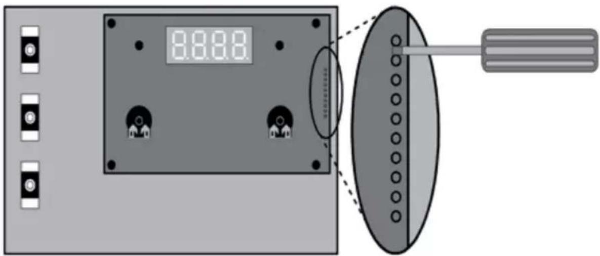
Refer to Fig. 1 (page 13) and die Fig. 5 (page 21).
- Connect the white wire for the sensor heater to terminal F1 on the terminal strip 2 ; it is not necessary to ensure correct polarity.
- Connect the red wire for the sensor heater to terminal TS on the terminal strip 2 ; it is not necessary to ensure correct polarity.
- Connect the white wire for the bench heater to terminal F2 on the terminal strip 2 ; it is not necessary to ensure correct polarity.
- Connect the heater, evaporator, power supply and light cables to the terminal strip 9 in accordance with the connection diagram (Fig. 5). Observe the operating instructions for the respective devices.
- Connect all earth conductors available to the earth conductor panel 5.
- For optional door monitor only:
Remove the jumper wire from the terminal DR on the terminal strip 2 and connect the wires for the door monitor. - Place the cover of the housing on the upper edge of the lower housing section and swivel the cover of the housing downwards until it engages audibly.
- Refit the temperature selector 1 and the humidity selector 11. Note the flat section of the slide-in shaft when fitting.
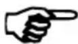
4.3. Installing the heater sensor with excess temperature fuse
Refer to Fig. 2 (page 15) and Fig. 5 (page 21).
Fig. 1

1 Temperature selector
2 Terminal strip for the heater sensor, bench sensor and door monitor
3 Fastening hole on the right
4 Cable bushing for the heater sensor, bench sensor and door monitor
5 Earth conductor terminal
6 Clip lock
7 Cable bushings for light, heater, evaporator and power supply cable
8 Fastening hole on the left
9 Terminal strip for light, heater, evaporator and power supply cable
10 Light fuse
11 Humidity selector
12 Attachment device
ATTENTION!
Sources of interference can have a negative effect on signal transmission
- Lay the heater sensor wires separately from other mains wires and control wires.
- Protect wires with only one layer of insulation by using a pipe (double insulation).
The heater sensor wires may only be extended under the following conditions:
- When a silicone cable resistant to temperatures up to 150 °C is used.
- The minimum cross-section of the wire totals 0.5 mm ^2
-
The length of the heater sensor wires may NOT exceed 10 m.
-
Lay the two 2-pin heater sensor wires ⑤ in the wall of the sauna cabin, lead them to the heater sensor installation location ④, and secure the heater sensor wires using wire clips.
- Pull the two half-shells 1 of the heater sensor apart.
- Connect the four connectors for the heater sensor wire in accordance with the connection diagram (Fig. 2).
- Carry out the tests as shown in section 4.6. Performing tests on page 17.
- Place the connection panel 2 crossways (as shown in Fig. 2) in the heater sensor half-shells 1.
- Place the two half-shells together and screw them together using the two cross-head screws ③ (9 mm).
- Check whether the heater sensor has been tightly closed.
- Install the heater sensor on the rear of the heater using the two wood screws enclosed ⑥ (16 mm). The optimum position is above the middle of the sauna heater. Maintain a distance of approx. 15 cm to the ceiling of the sauna cabin.
1 Heater sensor half-shells
2 Connection panel
3 Cross-head screws (9 mm)
4 Heater sensor
5 Heater sensor wires
6 Wood screws (16 mm)
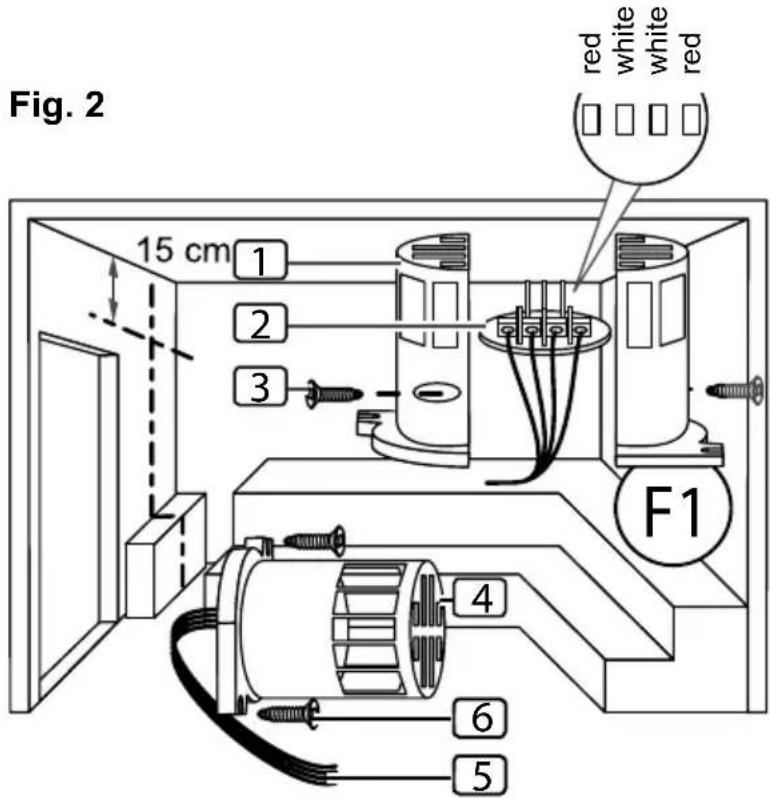
Fig. 3
1 Bench sensor half-shells
2 Connection panel
3 Cross-head screws (9 mm)
4 Bench sensor
5 Bench sensor wires
6 Wood screws (16 mm)
4.4. Installing the bench sensor
Refer to Fig. 3 (page 15) and Fig. 5 (page 21).
ATTENTION!
Sources of interference can have a negative effect on signal transmission
- Lay heater sensor wires separately from other mains wires and control wires.
- Protect wires with only one layer of insulation by using a pipe (double insulation).
The bench sensor wire may only be extended under the following conditions:
- When a silicone cable resistant to temperatures up to 150 °C is used.
- The minimum cross-section of the wire totals 0.5 mm ^2
-
The length of the bench sensor wires must NOT exceed 10 m.
-
Lay the two 2-pin bench sensor wire ⑤ in the wall of the sauna cabin, leading them to the bench sensor installation location ④ and secure the bench sensor wires using wire clips.
- Pull the two half-shells 1 of the bench sensor apart.
- Connect the two connectors for the heater sensor wire in accordance with the connection diagram (Fig. 5).
- Carry out the tests as shown in section 4.6. Performing tests on page 17.
- Place the connection panel 2 crossways (as shown in Fig. 3) in the heater sensor half-shells 1.
- Place the two half-shells together and screw them together using the two cross-head screws ③ (9 mm).
- Check whether the bench sensor has been securely closed.
- Install the bench sensor on the wall of the sauna cabin using the two wood screws 6 (16 mm) enclosed. The optimum position is opposite the sauna heater. Maintain a distance of approx. 15 cm to the ceiling of the sauna cabin.
4.5. Installing a door monitor (optional)
Install the door monitor according to the installation instructions for the product, or the sauna cabin manufacturer's instructions.
4.6. Performing tests
The following tests must be performed by a certified electrical fitter.
WARNING!
The following tests must be performed with the power supply switched on. There is a danger of electric shock.
- NEVER touch live parts.
- Check the contact of the earth conductors on the earth conductor terminal.
- Check the excess temperature fuse on the heater sensor F1.
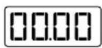
a. Switch on the control unit.
▶ 00.00 flashes on the display.
If an error message appears in the display, continue from point
- Troubleshooting for the installer on page 18.
b. Open the heater sensor and disconnect one of the two red wires for the heater sensor.
▶ The “E-12” error message appears and a continuous beep can be heard.
c. Reconnect the red wire for the heater sensor.
▶ 00.00 flashes on the display.
d. Now disconnect one of the white wires for the heater sensor.
▶ The “E-F1” error message appears and a continuous beep can be heard.
e. Reconnect the white wire for the heater sensor.
- Check the F2 bench sensor.
a. Switch on the control unit.
▶ 00.00 flashes on the display.
b. Open the bench sensor and disconnect one of the two white wires for the bench sensor.
▶ The “E-F2” error message appears and a continuous beep can be heard.
c. Reconnect the white wire for the bench sensor.
▶ 00.00 flashes on the display.
- Check the phase switching of the relay in sauna mode:
- Check the phase switching of the relay in combi mode:
5. Troubleshooting for the installer
Problem: the E-F1 error message appears in the display
Troubleshooting: check the heater temperature sensor
a. Disconnect all sauna control terminals from the mains.
b. Disconnect the white heater sensor wires from terminal F1 on the sauna control unit.
c. Measure the resistance on both ends of the cable.
▶ At room temperature ( 25 ^ C) the value must be 1.9–2.1 k .
Problem: the E-F2 error message appears in the display
Troubleshooting: check the bench temperature sensor
a. Disconnect all sauna control terminals from the mains.
b. Disconnect the white heater sensor wires from terminal F2 on the sauna control unit.
c. Measure the resistance on both ends of the cable.
▶ At room temperature ( 25 ^ C) the value must be 1.9–2.1 k .
Problem: the E-12 error message appears in the display
Troubleshooting: check the excess temperature fuse
a. Disconnect all sauna control terminals from the mains.
b. Disconnect the red heater sensor wires from terminal TS on the sauna control unit.
c. Measure the resistance on both ends of the cable.
▶ The value must be 0 kΩ (continuity).
If the measured values differ, check the wiring and the connection of the respective sensor.
Problem: the E-P1 or E-P3 error message appears in the display
The following troubleshooting steps must be performed by a certified electrical fitter.

WARNING!
The following tests must be performed with the power supply switched on. There is a danger of electric shock.
- NEVER touch live parts.
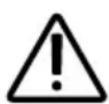
Troubleshooting: perform the calibration as follows:
a. Turn off the control unit. You do not need to completely disconnect the unit from the mains.
b. Carefully pull off the knobs of the temperature and humidity controller.
c. Remove the housing cover.
d. Turn the two knobs to the maximum setting (as far as they go to the right).
e. For the vertical 10-pin connector, short-circuit pin 9 and pin 10 using a suitable screwdriver, as shown in figure Fig. 4.
f. Pin 9 and pin 10 are the top 2 contacts.
g. Switch on the control unit.
h. The display shows P123 or P1.
i. Disconnect the connection between pin 9 and pin 10.
j. Wait about 5 seconds and then press the time button ⑨.
The display ② and control lights ① and ③ light up according to the operating mode.
Fig. 4
If a problem persists, consult your supplier.
6. Connection diagram
Fig. 5
Distributor
7. Operating elements
Fig. 6

① Humidity control light
② Display
3 Temperature control light
4 Temperature selector
5 Humidity symbol = max. temperature for combi mode
6 Humidity selector
7 Light switch
8 ON/OFF switch
9 Time button
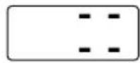
8. Meaning of the displays
Flashing display – self-test of the control unit, or the heating period has been exceeded (see 12. Troubleshooting for users on page 29)
Heating is in operation.

Heating is not in operation.

Evaporator is in operation.

Evaporator is not in operation.
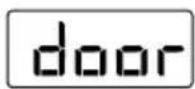
The door of the sauna cabin is open. (Only with optional door monitor)
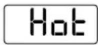
Temperature in the cabin is too high for combi mode.
Water in the evaporator is low
9. Operation
Refer to Fig. 6 on page 22.
9.1. Switching on the light
The light in the sauna cabin can be switched on and off regardless of which position the ON/OFF switch 8 is in.
To switch the light on or off, press the light switch 7.
9.2. Switching on the sauna control unit
WARNING!
Risk of fire
Flammable objects that are placed on the sauna heater could ignite and cause fires.
- NEVER place flammable objects on the sauna heater.
- Make sure that NO flammable objects have been placed on the sauna heater before the sauna control unit is switched on.
Press the ON/OFF switch ⑧ to switch on the sauna control unit.
▶ The control lights ① and ③ light up briefly.
▶ A beep can be heard.
▶ 00.00 flashes on the display 2.
▶ The sauna control unit is operational.
9.3. Starting sauna mode – Quick-start
- Use the temperature selector ④ to set the preferred sauna temperature. The further it is turned to the right, the higher the cabin temperature.
- Briefly press the time button 9.
▶ The sauna heater is switched on and begins to heat up.
▶ The control light ③ lights up.
9.4. Combi mode – Quick-start
-
Use the temperature selector ④ to set the preferred sauna temperature. The further it is turned to the right, the higher the sauna cabin temperature. In combi mode, the humidity symbol ⑤ shows the maximum temperature which can be set.
-
Use the humidity selector 6 to set the preferred humidity.
The further it is turned to the right, the higher the intensity.
- Briefly press the time button 9.
▶ The sauna heater and the evaporator are switched on and start to heat.
▶ The control lights ① and ③ light up.
9.5. Sauna mode with preset time (starting the time-delay)

WARNING!
Risk of fire
Flammable objects that are placed on the sauna heater could ignite and cause fires.
- NEVER place flammable objects on the sauna heater.
- Make sure that NO flammable objects have been placed on the sauna heater before you activate the preset timer function.
You can set the preset time to increments of 15 minutes. The maximum preset time totals 23 hours and 45 minutes. The preset time is displayed in hours and minutes, e.g. 8 hours and 15 minutes is displayed as 8.15.
-
Use the temperature selector ④ to set the preferred sauna temperature. The further it is turned to the right, the higher the cabin temperature.
-
Press and hold the time button 9.
▶ The display ② begins at 00.00 and increases in increments of 15 minutes.
- Once you have reached the required preset time, release the time button ⑨.
▶ The timer is running, and the remaining preset time appears in the display 2 .
▶ The dot between the hours and minutes on the display ② flashes.
▶ Once the preset time has elapsed, the sauna heater switches on.
9.6. Combi mode with preset time (starting the time-delay)

WARNING!
Risk of fire
Flammable objects that are placed on the sauna heater could ignite and cause fires.
- NEVER place flammable objects on the sauna heater.
- Make sure that NO flammable objects have been placed on the sauna heater before you activate the preset timer function.
You can set the preset time to increments of 15 minutes. The maximum preset time totals 23 hours and 45 minutes. The preset time is displayed in hours and minutes, e.g. 8 hours and 15 minutes is displayed as 8.15.
- Use the temperature selector 4 to set the preferred sauna temperature. The further it is turned to the right, the higher the cabin temperature. In combi mode, the humidity symbol 5 shows the maximum temperature which can be set.
- Use the humidity selector 6 to set the preferred humidity. The further it is turned to the right, the higher the intensity.
- Press and hold the time button 9.
▶ The display ② begins at 00.00 and increases in increments of 15 minutes.
- Once you have reached the required preset time, release the time button ⑨.
▶ The timer is running, and the remaining preset time appears in the display 2 .
▶ The dot between the hours and minutes on the display ② flashes.
▶ Once the preset time has elapsed, the sauna heater and evaporator switch on.
9.7. Deleting the preset time
Briefly press the time button 9.
▶ The preset time is cancelled.
The display ② and control lights ① and ③ light up according to the operating mode (see 8. Meaning of the displays on page 22)
9.8. Switching off the sauna control unit
To turn off the sauna control unit after using the sauna, press the ON/OFF switch 8.
▶ The display ② goes out.
9.9. Extended periods of non-use
If you will not be using the sauna for an extended period of time, switch the main fuse of the sauna control off in the fuse box.
9.10. How the optional door monitor works
During the preset time
If a person enters the sauna cabin while the timer is running, they might place flammable objects on the cold sauna heater. Once the preset time begins, the sauna heater begins to heat the cabin. Flammable objects on the sauna heater ignite and cause a fire. The door monitor is meant to prevent this.
The preset time was set (see section 9.5 and 9.6).
▶ The timer is running and the sauna heater is not yet heating up.
The cabin door is opened.
▶ A recurring beep can be heard.
▶ The message “door” appears in the display 2.
▶ The preset time is cancelled.
▶ After the cabin door is closed, the preset time must be set again.
While the sauna heater is heating
The cabin temperature is below 40^ C and the cabin door is opened.
▶ A recurring beep can be heard.
▶ The message “door” appears in the display 2.
▶ After the cabin door is closed, the sauna control unit must be started again.
The cabin temperature is above 40 °C . The door monitor is no longer used for fire prevention, but as a power-saving feature.
When the cabin door is opened for less than 5 seconds, there is no message.
The cabin door is opened for more than 5 seconds:
▶ A recurring beep can be heard.
▶ The control light ③ flashes.
▶ The sauna heater is switched off.
▶ The message “door” appears in the display 2 .
▶ After the cabin door is closed, the sauna heater is switched on again, the beeping stops, and the message “door” disappears.
EN
10. Cleaning and maintenance
10.1. Cleaning
ATTENTION!
Damage to the unit
The sauna control unit is protected against jets of water, however direct contact with water could still damage the unit.
- NEVER immerse the device in water.
- Never pour water over the device.
-
Never clean the device with a cloth which is too wet.
-
Immerse a cleaning cloth in a mild, soapy solution.
- Wring the cleaning cloth out well.
- Wipe the sauna control unit housing carefully.
10.2. Maintenance
The sauna control unit is maintenance-free.
11. Disposal
- Dispose of packaging materials in accordance with the applicable disposal regulations.
- Used devices contain reusable materials, as well as hazardous substances. Do not dispose of your used device with household waste, but do so in accordance with the locally applicable regulations.
12. Troubleshooting for users
Refer to Fig. 6 (page 22).
12.1. Exceeding the heating period
Problem: "00.00" is flashing in the display 2.
Cause: After running for 6 hours, the sauna control unit automatically switches off the sauna heater for safety reasons (heating period limit).
How to solve the problem:
To start up the sauna control unit again, press and release the time button ⑨.
▶ The sauna heater is switched on and begins to heat up.
▶ The display ② and control lights ① and ③ light up according to the operating mode.
12.2. Light does not operate
How to solve the problem:
- Switch off the sauna control unit using the ON//OFF switch 8.
- Switch off the main fuse of the sauna control unit in the fuse box.
- Change the bulbs used for lighting the sauna.
- Switch the main fuse back on.
- Press switch 7.
▶ If the light still does not operate, inform your supplier.
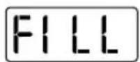
12.3. Low-water display
The sauna control unit features an automatic low-water display which is active in combi mode.
Problem: "FILL" is flashing in the display 2.
Cause: The water tank in the evaporator is empty.
How to solve the problem:
Pour water into the water tank in the evaporator.
▶ After a short while, the text “FILL” disappears and the evaporator starts heating up.
12.4. Error messages
Error messages in the display 2
An error message indicates an electrical malfunction in the system. The sauna control unit is no longer operational.
- Note the error message.
- Switch off the sauna control unit.
- Switch off the main fuse of the sauna control unit in the fuse box.
- Contact customer service.
Error Description Cause/rectification
| E-F1 Short circuit/broken wire/ heater sensor defective. | See point 5. Troubleshooting for the installer on page 18 | |
| E-F2 Short circuit/broken wire/ bench sensor defective. | See point 5. Troubleshooting for the installer on page 18 | |
| E-12 Broken wire or damage to the excess temperature protection. | See point 5. Troubleshooting for the installer on page 18 | |
| E-P1 E-P3 | Software error See item | 5. Troubleshooting for the installer on page 18 |
13. Technical data
Ambient conditions
| Storage temperature: | -25 °C to +70 °C | |
| Ambient temperature: | -10 °C to +40 °C | |
| Relative humidity: | max. |
Sauna control unit
| Dimensions: 238 x 195 x 90 mmSwitched voltage/three-phase 3N: 400 VFrequency: Contact rating of heater AC 1: 3 x 3 kWSwitched current per phase of heater AC 1: 13 AContact rating of Evaporator AC 1: 3 kWSwitched current of Evaporator AC 1: 13 ARated power: Min./max. input power: 4.3/6.3 VAProtection type (protected against jets of water): IP X4Temperature setting range: +40 °C to +125 °CConnection to the mains supply as fixed wiring (fixed connection) | 50 Hz | |
| 230 V |
Light
| Contact | rating: | 100 | W | |
| Fuse: | 1A T |
Thermal safety
Heater sensor with excess temperature fuse (139 °C shut-off temperature) Automatically switches off after 6 hrs. (heating period limit) Two sensor system with temperature control above the heater or bench.
Connection cables
| Power supply cable: | min. 5 × 2.5 mm^2 |
| Heater supply cable: | min. 1.5 mm^2 |
| Evaporator cable: | min. 1.5 mm^2 |
| Sensor | wires: | min. | 0.5 |
| Light | wire: | min. | 1.5 |
Temperature resistance
| Heater, evaporator, light and sensor wires min. 150 °C |
| Power supply cable min. 90 °C |
Preset time function
| Minimum preset time | 15 minutes | |
| Maximum preset time | 23 hours 45 minutes | |
| Interval | 15-minute | increments |
- Sauna and evaporator control unit
- Modern Bio
- Table of Contents
- Operation 23
- Cleaning and maintenance 28
- Disposal 28
- Troubleshooting for users.
- Technical data 31
- About this instruction manual
- Symbols used for warnings
- DANGER!
- WARNING!
- CAUTION!
- ATTENTION!
- Other symbols
- Important information for your safety
- Intended use
- Safety information for the installer
- Safety information for the user
- Product description
- Scope of delivery
- Product functions
- Installation and connection
- Damage to the unit
- Installing the sauna control unit
- Refer to Fig. 1 (page 13).
- Connecting wires
- Installing the heater sensor with excess temperature fuse
- Sources of interference can have a negative effect on signal transmission
- Installing the bench sensor
- Installing a door monitor (optional)
- Performing tests
- Troubleshooting for the installer
- Problem: the E-12 error message appears in the display
- Troubleshooting: check the excess temperature fuse
- Problem: the E-P1 or E-P3 error message appears in the display
- Troubleshooting: perform the calibration as follows:
- Connection diagram
- Operating elements
- Meaning of the displays
- Operation
- Switching on the light
- Switching on the sauna control unit
- Risk of fire
- Starting sauna mode – Quick-start
- Combi mode – Quick-start
- Sauna mode with preset time (starting the time-delay)
- Combi mode with preset time (starting the time-delay)
- Deleting the preset time
- Switching off the sauna control unit
- Extended periods of non-use
- How the optional door monitor works
- During the preset time
- While the sauna heater is heating
- Cleaning and maintenance
- Cleaning
- Maintenance
- Disposal
- Troubleshooting for users
- Exceeding the heating period
- How to solve the problem:
- Light does not operate
- Low-water display
- Error messages
- Error messages in the display 2
- Technical data
- Thermal safety
Brand : Karibu
Model : Mia
Category : Sauna