CHP36100SS - Basket BEKO - Free user manual and instructions
Find the device manual for free CHP36100SS BEKO in PDF.
| Product Type | Decorative Hood |
| Brand | Beko |
| Model | CHP36100SS |
| Width | 36 inches (91.4 cm) |
| Maximum Suction Power | 910 CFM (cubic feet per minute) |
| Number of Speeds | 4 speeds |
| Control | Mechanical (push-button switches) |
| Lighting | 2 LED bulbs, 6.5 W each (GU10 base) |
| Filter Type | 2 metal baffle filters |
| Voltage | 120 V |
| Frequency | 60 Hz |
| Total Power (motor + lighting) | 900 W |
| Vent Type | Exterior only (ducted) |
| Duct Diameter | 10 inches (25.4 cm) round, metal recommended |
| Minimum Distance Above Cooktop | 30 inches (76.2 cm) for gas or electric |
| Material | Stainless steel |
| Warranty | 2-year limited warranty |
Frequently Asked Questions - CHP36100SS BEKO
User questions about CHP36100SS BEKO
0 question about this device. Answer the ones you know or ask your own.
Ask a new question about this device
Download the instructions for your Basket in PDF format for free! Find your manual CHP36100SS - BEKO and take your electronic device back in hand. On this page are published all the documents necessary for the use of your device. CHP36100SS by BEKO.
USER MANUAL CHP36100SS BEKO
natural_image
Simple line drawing of a kitchen range hood with three circular buttons (no text or symbols)CHP 30100 CF/CHP 30100 SS
CHP 36100 CF/CHP 36100 SS
EN | ES | FR |
8650842206887
LIB0162718A

text_image
bekoPlease read this manual first!
Dear Customers!
Thank you for preferring a Beko product. We hope that you get the best results from your product which has been manufactured with high quality and state-of-the-art technology. Therefore, please read this entire user manual and all other accompanying documents carefully before using the product and keep it as a reference for future use. If you handover the product to someone else, give the user manual as well. Follow all warnings and information in the user manual.
Remember that this user manual is also applicable for several other models. Differences between the models are explicitly described in the manual.
Meanings of the Symbols
Following symbols are used in the various section of this manual:

Important information and useful hints about usage.

WARNING: Warnings for dangerous situations concerning the safety of life and property.
Warning for electric shock.
Warning for hot surfaces.

This product has been manufactured in environmental friendly modern plants without giving any harm to the nature.
CONTENTS
1 Read and save these instructions 4
1.1 Important safety Notice 4
2 Electrical & Installation requirements 7
2.1 Electrical requirements....7
2.2 Before installing the hood .....7
3 Technical specifications of your appliance 8
3.1 List of Materials 8
3.1.1 Parts supplied 8
3.1.2 Parts not supplied 8
3.2 Dimensions and Clearances 9
3.3 Ducting Options and Examples.....9
3.3.1 Venting methods....9
3.4 Preparation 9
4 Installing your appliance 11
4.1 Installation - Ducting version.... 11
4.2 install hood onto wall 11
4.2.1 Install Transition Onto Top of Hood..... 11
4.2.2 Hang hood on wood support....12
4.2.3 Install bottom mounting screws .....12
4.3 install hood ceiling or beneath cabinets ..12
4.3.1 Install Transition Onto Top of Hood.....13
4.3 2 Mount hood onto ceiling or cabinet .....13
4.3.3 Connecting the ductwork ..... 14
4.3.4 Electrical connection....14
4.3.5 Install Motor....14
5 Operating your appliance 16
5.1 Description of the hood & Controls ..... 16
5.1.1 Controls....16
5.1.2 Description of control panel....16
6 Cleaning and maintenance 17
6.1 Maintenance 17
6.2 Cleaning....17
6.3 Grease Filter 17
6.3.1 Remove grease filters....17
6.3.2 install grease filters....17
6.4 Replacing the light bulb....17
7 Warranty 19
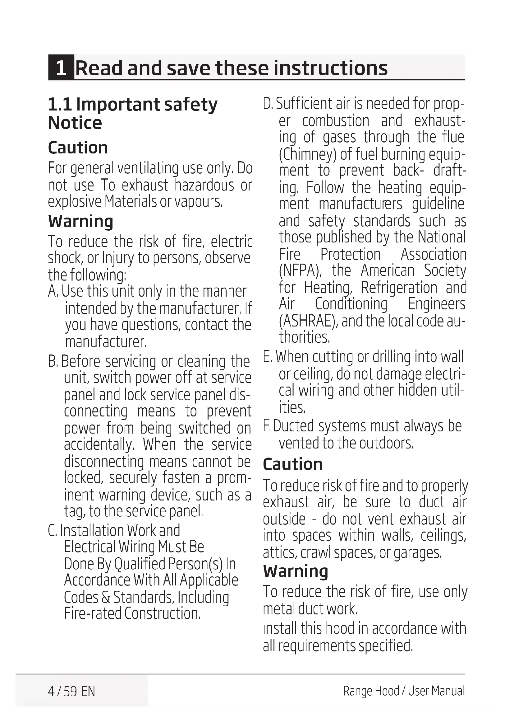
1 Read and save these instructions
1.1 Important safety Notice
Caution
For general ventilating use only. Do not use To exhaust hazardous or explosive Materials or vapours.
Warning
To reduce the risk of fire, electric shock, or Injury to persons, observe the following:
A. Use this unit only in the manner intended by the manufacturer. If you have questions, contact the manufacturer.
B. Before servicing or cleaning the unit, switch power off at service panel and lock service panel disconnecting means to prevent power from being switched on accidentally. When the service disconnecting means cannot be locked, securely fasten a prominent warning device, such as a tag, to the service panel.
C. Installation Work and Electrical Wiring Must Be Done By Qualified Person(s) In Accordance With All Applicable Codes & Standards, Including Fire-rated Construction.
D. Sufficient air is needed for proper combustion and exhausting of gases through the flue (Chimney) of fuel burning equipment to prevent back-drafting. Follow the heating equipment manufacturers guideline and safety standards such as those published by the National Fire Protection Association (NFPA), the American Society for Heating, Refrigeration and Air Conditioning Engineers (ASHRAE), and the local code authorities.
E. When cutting or drilling into wall or ceiling, do not damage electrical wiring and other hidden utilities.
F. Ducted systems must always be vented to the outdoors.
Caution
To reduce risk of fire and to properly exhaust air, be sure to duct air outside - do not vent exhaust air into spaces within walls, ceilings, attics, crawl spaces, or garages.
Warning
To reduce the risk of fire, use only metal duct work.
install this hood in accordance with all requirements specified.
1 Read and save these instructions
Warning
To Reduce The Risk Of Fire Or Electric Shock, Do Not Use This Hood With Any External Solid State Speed Control Device.
Warning
To reduce the risk of a range top grease fire.
A. Never leave surface units un-attended at high settings. Boilovers cause smoking and greasy spillovers that may ignite. Heat oils slowly on low or medium settings.
b. Always turn hood ON when cooking at high heat or when flam-being food (i.e. Crepes Suzette, Cherries Jubilee, Peppercorn Beef Flambe').
c. Clean ventilating fans frequently. Grease should not be allowed to accumulate on fan or filter.
d. Use proper pan size. Always use cookware appropriate for the size of the surface element.
Warning
To reduce the risk of injury to persons, in the event of a range top grease fire, observe the following:
a. Smother flames with a close-fitting lid, cookie sheet, or other metal tray, then turn off the gas burner or the electric element. Be careful to prevent burns. If the flames do not go out immediately, evacuate and call the fire department.
b. Never pick up a flaming pan - you may be burned.
c. Do not use water, including wet dishcloths or towels - a violent steam explosion will result.
d. Use an extinguisher only if:
- You know you have a class ABC extinguisher, and you already know how to operate it.
- The fire is small and contained in the area where it started.
- The fire department is being called.
- You can fight the fire with your back to an exit.
a Based on "Kitchen Fire Safety Tips" published by NFPA.
Operation
a. Always leave safety grills and filters in place. Without these components, operating blowers could catch onto hair, fingers and loose clothing.
1 Read and save these instructions
The manufacturer declines all responsibility in the event of failure to observe the instructions given here for installation, maintenance and suitable use of the product.
The manufacturer further declines all responsibility for injury due to negligence and the warranty of the unit automatically expires due to improper maintenance.
2 Electrical & Installation requirements
2.1 Electrical requirements

Observe all governing codes and ordinances.
It is the customer's responsibility:
To contact a qualified electrical installer. To assure that the electrical installation is adequate and in conformance with National Electrical Code, ANSI/NFPA 70 – latest edition*, or CSA Standards C22.1-94, Canadian Electrical Code, Part 1 and C22.2 No.0-M91 - latest edition** and all local codes and ordinances.
- If codes permit and a separate ground wire is used, it is recommended that a qualified electrician determine that the ground path is adequate.
- Do not ground to a gas pipe.
- Check with a qualified electrician if you are not sure range hood is properly grounded.
- Do not have a fuse in the neutral or ground circuit.

Save Installation Instructions for electrical inspector's use.

The range hood must be connected with copper wire only.

The range hood should be connected directly to the fused disconnect (Or circuit breaker) box through metal electrical conduit.
Wire sizes must conform to the requirements of the National Electrical Code ANSI/NFPA 70 – latest edition*, or CSA Standards C22.1-94, Canadian Electrical Code Part 1 and C22.2 No. 0-M91 - latest edition** and all local codes and ordinances.
A U.L.- or C.S.A.-listed conduit connector must be provided at each end of the power supply conduit (at the range hood and at the junction box).
Copies of the standards listed may be obtained from:
* National Fire Protection Association
Batterymarch Park Quincy, Massachusetts 02269
** CSA International 8501 East Pleasant Valley Road Cleveland, Ohio 44131-5575
2.2 Before installing the hood
- For the most efficient air flow exhaust, use a straight run or as few elbows as possible.

WARNING: Vent unit to outside of building, only.
- At least two people are necessary for installation.
e3. Fittings material is provided to secure the hood to most types of walls/ceilings, consult a Qualified Installer, check if they perfectly fit with your cabinet/wall. - Do not use flex ducting.
- COLD WEATHER installations should have an additional backdraft damper installed to minimize backward cold airflow and a nonmetallic thermal break to minimize conduction of outside temperatures as part of the ductwork. The damper should be on the cold air side of the thermal break. The break should be as close as possible to where the ducting enters the heated portion of the house.
- Make up air: Local building codes may require the use of Make-Up Air Systems when using Ducted Ventilation Systems greater than specified CFM of air movement. The specified CFM varies from locale to locale. Consult your HVAC professional for specific requirements in your area.
Removing the packaging

Remove carton carefully, Wear gloves to protect against sharp edges.

WARNING: Remove the protective film covering the product before putting into operation.
3 Technical specifications of your appliance
3.1 List of Materials
3.1.1 Parts supplied
Removing the packaging

Remove carton carefully, Wear gloves to protect against sharp edges.

WARNING: Remove the protective following the product before putting into operation.
- Hood canopy.
- Blower.
- Duct transition.
- Lamp already installed.
- Grease filter.
- Hardware bag with:
- Use, care and installation guide
- 2 hollow wall anchors with 2 screws to secure hood to the wall at the bottom
- 4 Wood screws to secure the wood support to the wall
- 4 PZ head screws to secure the transition to the hood outlet on the top
- 6 Phillips head screws to secure hood to the cabinet
- 4 Safety screws and 4 lock washers to secure the blower
- 2 Flat washers for hollow wall anchors
- Torx 20 adapter
3.1.2 Parts not supplied
Tools/Materials required
- Wire nuts
-
10" rounded metal duct length to suit installation
-
Measuring tape
- Pliers
- Gloves
- Knife
- Safety glasses
• Electric drill with 5/16" and 3/8" Bits - Strain relief
- Spirit level
- Duct tape
- Screwdrivers:
- Phillips (Posidrive) # 2
- Torx # 2
- Wire cutter/stripper
- Masking tape
- Hammer
- Saw, jig saw or reciprocating saw
| Operating mode | ducted out only |
| Max. Ventilation Capacity | 30" - 500 CFM36" - 910 CFM |
| Nr.of Speeds | 4 |
| Controls | Mechanical Knobs |
| Lights | 2 x 6.5 W LED |
| Filtering | 2 x Baffle Filters |
| Volts | 120 V |
| Frequency | 60 Hz |
| Total Power (motor + lamps) | 30" - 450 W36" - 900 W |
| Plug type | Hard Wire |
| Required distance above cooktop | 30" (gas cooktop) |
| 30" (electrical cooktop) |
3 Technical specifications of your appliance
3.2 Dimensions and Clearances
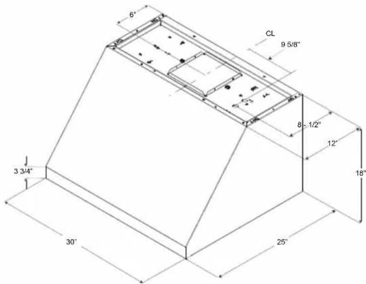
text_image
6" CL 9 5/8" 8 - 1/2" 12" 3 3/4" 18" 30" 25"3.3 Ducting Options and Examples
Closely follow the instructions set out in this manual.
All responsibility, for any eventual inconveniences, damages or fires caused by not complying with the instructions in this manual, is declined.
3.3.1 Venting methods
Vent Exhaust Option
The hood is equipped with a transition B for discharge of fumes to the outside (Ducting version).
Minimum Duct Size (Ducting/Ductless version): 10" Round Pipe.
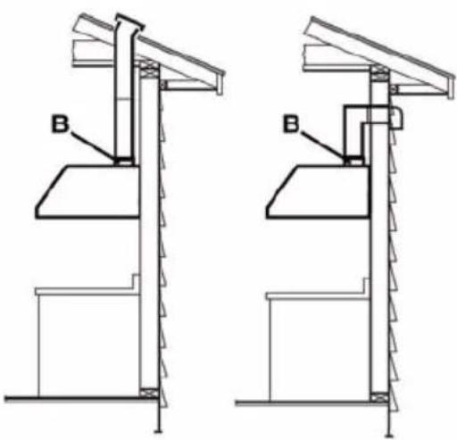
text_image
Technical diagram showing two mechanical assembly configurations labeled B, with structural supports and mounting brackets.Vertical discharge
3.4 Preparation
Do not cut a joist or stud unless absolutely necessary. If a joist or stud must be cut, then a supporting frame must be constructed.
Fittings material is provided to secure the hood to most types of walls/ceilings.
However, a technician must verify suitability of the materials in accordance with the type of wall/ceiling.
3 Technical specifications of your appliance
Before making cutouts, make sure there is proper clearance within the ceiling or wall for exhaust vent.
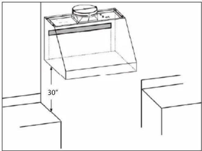
Hood installation height above cooktop is the users preference. The lower the hood is above the cooktop, the more efficient the capturing of cooking odors, grease and smoke.

WARNING: For gas ranges installation: mount this hood so that the bottom edge is at 30" (76,2 cm) above the cooking surface.
For electric ranges installation: mount this hood so that the bottom is not less than 30" (76,2 cm) and not more that 36" above the cooking surface.
Household use. Please, read installation manual for specific application.
Check your ceiling height and the hood height maximum before you select your hood.
4 Installing your appliance
4.1 Installation - Ducting version
- If possible, disconnect and move freestanding or slide-in range from cabinet opening to provide easier access to rear wall. Otherwise put a thick, protective covering over countertop, cooktop or range to protect from damage and debris. Select a flat surface for assembling the unit. Cover that surface with a protective covering and place all canopy hood parts and hardware in it.
- Determine and mark the centerline on the wall where the canopy hood will be installed.
- Select a mounting height comfortable for the user and mark on wall.
4.2 install hood onto wall

IMPORTANT: Framing must be capable of supporting up to 150 lbs.
- Locate at least.2 vertical studs at the wood support.
- Center the supplied wood support, left to right and below the 15 3/8" marked line.
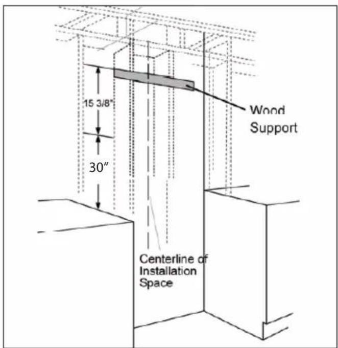
text_image
15 3/8" 30" Wood Support Centerline of Installation Space- Secure the wood support to 2 or more vertical studs, using at least 2 of the 4 supplied long screws.

IMPORTANT: Screws must penetrate at least 1 1/2" into vertical studs. Countersink screws into support.

The mounting screws must remain in their original shipping location. These screws are positioned to engage the keyhole slots in the back of the hood.
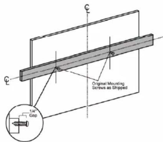
text_image
Original Mounting Screws as Shipped 1/4" Gap- Adjust depth of original mounting srcrews in the wood support until they protrude 1/4" forward. This 1/4" gap will provide clearance to hang the hood.
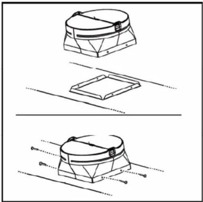
4.2.1 Install Transition Onto Top of Hood

IMPORTANT: Remove shipping tape from damper and check that damper moves freely.
- Place the transition piece over the hood exhaust and secure with 4 screws provided.
- Use duct tape to seal the connection. Check to be sure the damper moves freely.
4 Installing your appliance
natural_image
Technical line drawings of a mechanical component with three views (top, front, side), no text or symbols present.4.2.2 Hang hood on wood support
- Lift the hood and hold close to the installation location. Route house wiring through the knockout and into the junction box.
- Place the hood over the wood support. Be sure the mounting screws engage the keyhole slots in the back of the hood.
Tighten the screws.

WARNING: Continue to provide additional support while the hood is mounted with only these 2 screws.
These screws will not support the weight of the hood. The hood could fall resulting in damage or personal injury.
- Check to be sure the hood is level and centered.
text_image
30"4.2.3 Install bottom mounting screws
- Drill 1/8" pilot holes into the two lower mounting holes. Enlarge the holes if they did not enter studs to 3/8". Insert anchors for wall fasteners into bottom holes. Remove anchor screws and add flat washers provided. Drive screws into anchors and tighten. - Install 4 additional screws through the back of the hood and into the wood support.
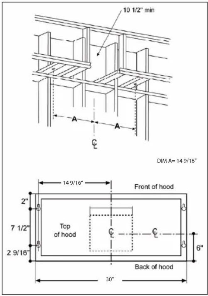
4.3 install hood ceiling or beneath cabinets
(Skip this step if using wall mounting method)

IMPORTANT: Ceiling framing must be capable of supporting up to 150 lbs.
• The ceiling should be constructed with 2x4's.
• Determine the installation location on the wall.
- Continue the centerline forward on the bottom of the cabinet or ceiling.
- The opening above the hood should allow for the 10" round duct and clearance to slide the hood back against the wall.
- The 2x4 studs must be located as shown in the chart, Dim. A to accept monting screw.
- Drill 1/8" pilot holes into the studs at the locations show in the illustration.
4 Installing your appliance
text_image
10 1/2" min A A C DIM A= 14 9/16" 14 9/16" Front of hood 2" 7 1/2" Top of hood 2 9/16" Back of hood 30"4.3.1 Install Transition Onto Top of Hood
IMPORTANT: Remove shipping tape from damper and check that damper moves freely.
- Place the transition piece over the hood exhaust and secure with 4 screws provided.
- Use duct tape to seal the connection. Check to be sure the damper moves freely.
natural_image
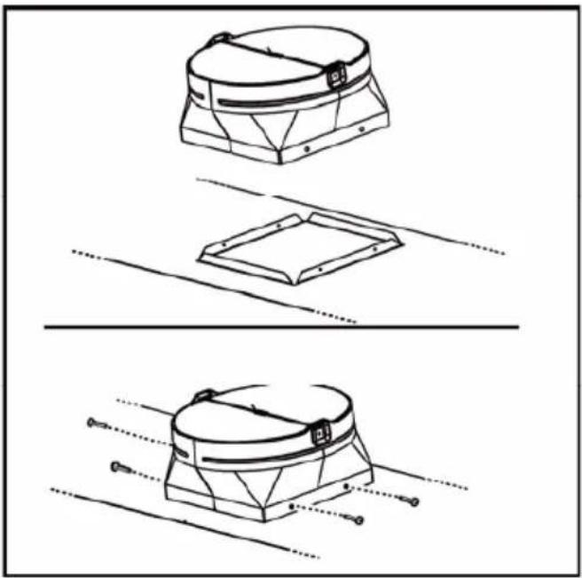
Three technical line drawings of a mechanical component with no visible text or symbols4.3 2 Mount hood onto ceiling or cabinet

If mounting to the underside of a cabinet with a recessed bottom, install shims to fill the gap.
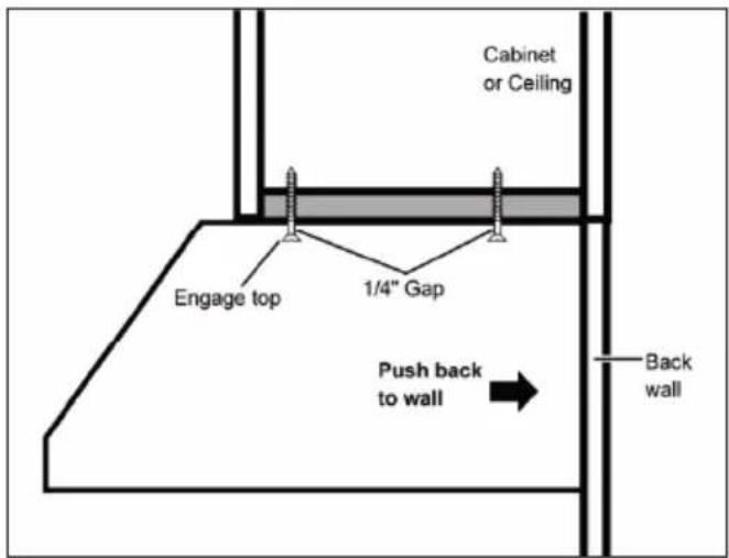
- Drive mounting screws into the studs until they protrude 1/4". The 1/4" gap will provide clearance to engage the keyhole slots in the top of the hood.
- Lift hood to installation position. Locate house wiring and route trough the knockout (from the back or top of the hood).
- Lift hood onto mounting screws. Slide back against the rear wall.
- Tighten mounting screws.

IMPORTANT: For additional support and to minimize vibration during operation, the hood must be secured to the back wall. Use wall anchors to fasten bottom back of hood to the wall.
4 Installing your appliance
text_image
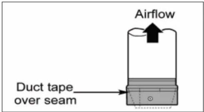
Cabinet or Ceiling Engage top 1/4" Gap Push back to wall Back wall4.3.3 Connecting the ductwork
• Install ductwork, making connections in the direction of airflow as illustrated.
- Push duct over the exhaust outlet.
- Wrap all duct joints and the flange connections with duct tape for an airtight seal.
• Make the same connection in the wall or ceiling vent exit.
text_image
Airflow Duct tape over seam4.3.4 Electrical connection
Electrical Shock Hazard
Turn off power circuit at the service panel before wiring this unit. 120 VAC, 15 or 20 Amp circuit required.
Electrical grounding instructions
This appliance is fitted with an electrical junction box with 3 wires, one of which (green/yellow) serves to ground the appliance.
To protect you against electric shock, the green and yellow wire must be connected to the grounding wire in your home electrical system, and it must under no circumstances be cut or removed.
Failure to do so can result in death or electrical shock.
Remove the knockout and the Junction box cover and install the conduit connector (cULus listed) in junction box.
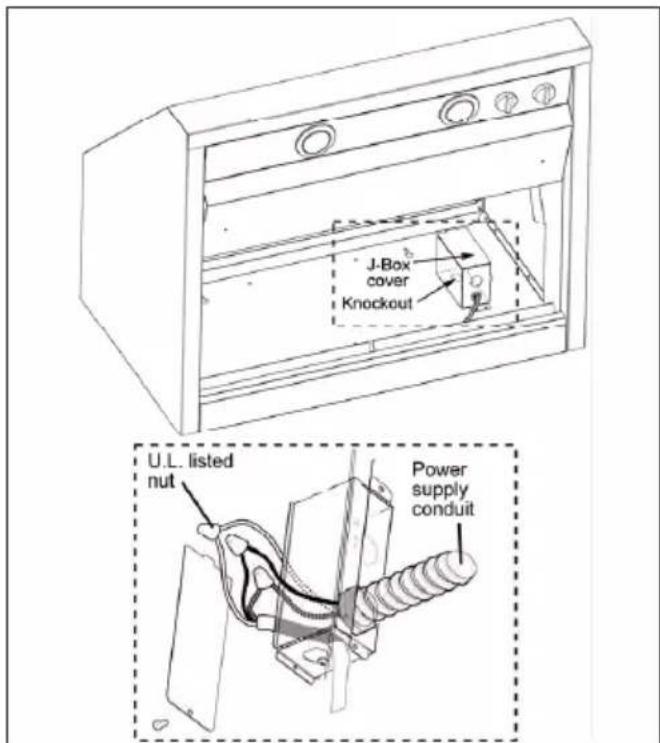
text_image
J-Box cover Knockout U.L. listed nut Power supply conduit4.3.5 Install Motor
• From the inside of the hood, slip motor into the attachment slot on the left.
- Rotate motor upwards until it snaps into the spring clip on the right.
- Secure the motor to the hood with the 2 machine screws and 2 lock washers.
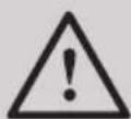
IMPORTANT: Connector ends are designed to mate only one way. Match flat and round connectors as shown.
4 Installing your appliance
- Plug connector into the motor.
text_image
Outlet Attachment slot Spring clip Attachment screw Attachment screw Spring clipFig. 1: Single motor installation (30" range hood model only)
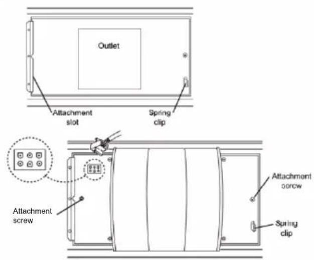
text_image
Diagram of a door lock mechanism with labeled parts A, B, and C, showing internal components and structural details.A. Mounting hole
B. Washer
C. Mounting screw
Install the grease ter and turn power on at service panel.
Check operation of the hood.
If range hood does not operate:
- Check that the circuit breaker is not tripped or the house fuse blown.
- Disconnect power supply. Check that wiring is correct.
To get the most efficient use from your new range hood, read the "Use and Care Information" section.
Keep your Installation Instructions and Use and Care Guide close to range hood for easy reference.
5 Operating your appliance
5.1 Description of the hood & Controls
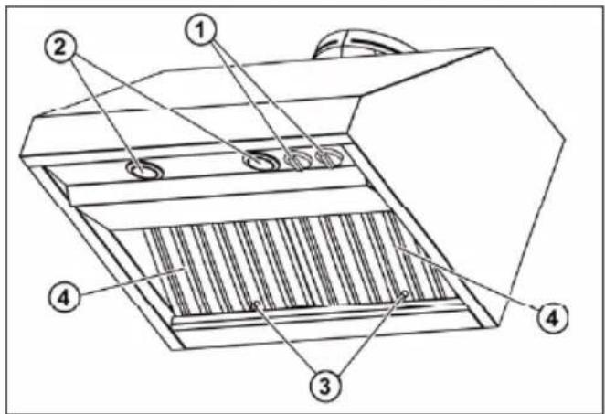
text_image
Technical diagram of a mechanical device with numbered components for identification- Blower and light controls
- Lamp housings
- Grease filter Handle
- Grease filter
5.1.1 Controls
Use the high suction speed in cases of concentrated kitchen vapours. It is recommended that the cooker hood suction is switched on for 5 minutes prior to cooking and to leave in operation during cooking and for another 15 minutes approximately after terminating cooking.
5.1.2 Description of control panel
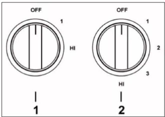
text_image
OFF 1 HI 1 OFF 1 2 3 HI 2- Light Control
- Turn the light control from OFF to HI for the brightest light while cooking.
- Fan Control
- Turn the fan control speed from OFF to HI as needed.
6 Cleaning and maintenance
6.1 Maintenance

Before performing any maintenance operation, isolate the hood from the electrical supply by switching off at the connector and removing the connector fuse.
Or if the appliance has been connected through a plug and socket, then the plug must be removed from the socket.
6.2 Cleaning
- The cooker hood should be cleaned regularly (at least with the same frequency with which you carry out maintenance of the fat filters) internally and externally. Clean using the cloth dampened with neutral liquid detergent. Do not use abrasive products. DO NOT USE ALCOHOL!

WARNING: Failure to carry out the basic cleaning recommendations of the cooker hood and replacement of the filters may cause fire risks.
- Therefore, we recommend oserving these instructions.
- The manufacturer declines all responsibility for any damage to the motor or any fire damage linked to inappropriate maintenance or failure to observe the above safety recommendations.
6.3 Grease Filter
Traps cooking grease particles.
This must be cleaned once a month using non aggressive detergents, either by hand or in the dishwasher, which must be set to a low temperature and a short cycle. When washed in a dishwasher, the grease filter may discolour slightly, but this does not affect its filtering capacity.
6.3.1 Remove grease filters
- To remove the filters, grasp the handle, push the filter up and lift out.
6.3.2 install grease filters
- Place filter drip trays into the rear of the hood.
- Insert the grease filter into opening and drop into the trays.
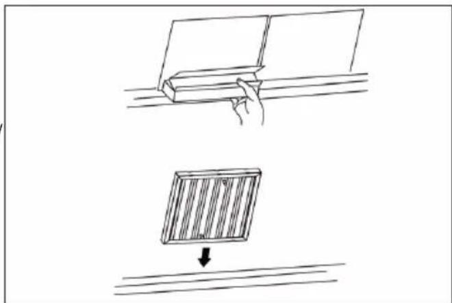
natural_image
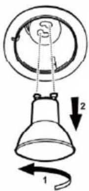
Diagram showing a hand holding a rectangular object above a grid-patterned panel, with an arrow indicating downward motion (no text or symbols)6.4 Replacing the light bulb

Before replacing the lamps, switch power off at service panel and lock service panel disconnecting means to prevent power from being switched on accidentally.

Turn off the lights and fan. Allow the lights to cool before handling. If new lights do not operate be sure lights are inserted correctly before calling service.
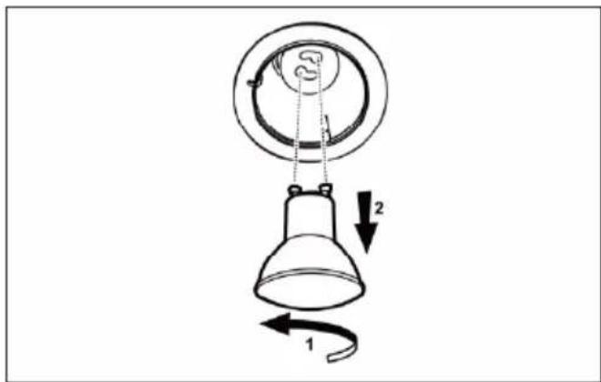
text_image
Diagram of a lamp with labeled parts and directional arrows indicating motion or rotation.6 Cleaning and maintenance
Replace Lights
- Remove the damaged light (twist counter clockwise) and replace with a new 120 Volts, 6.5 W, Led light made for a GU10 base, suitable for use in open luminare.
Warranty Statement For Beko Range Hoods
Cooking Appliances
The warranties provided by Beko Bekese statements only apply to cooking appliances(wall ovens / cooktops) sold to the original purchaser or homeowner
in the US and Canada. The warranty is not transferable. To obtain warranty service, please contact our nearest distributor as listed by state. You will need your cooking appliances(wall ovens / cooktops) model number, serial number, retailer name and address, where purchased and purchase date / installation date. This warranty gives you specific legal rights, and you may also have other rights which vary from state to state.
2 year* limited warranty from date of first installation Beko will repair or replace at no cost to the consumer any defective parts of the cooking appliances(wall ovens / cooktops) if used under normal household conditions (warranty is void if the product is used commercially). Service must also be performed by an authorized Beko service agency otherwise the warranty is void. (Cosmetic defects must be reported within 10 business days from installation)
Disclaimers of warranties and exclusions: Warranty does not cover service costs by an authorized service agent to correct installation, electrical problems or educational instruction on the use of the cooking appliances(wall ovens / cooktops). The warranty also does not cover defects or damage caused by an act of god (such as storms, floods, fires, mudslides, etc.), damage cause by use of the cooking appliances(wall ovens / cooktops) for purposes other than those for which it was designed, misuse, abuse, accident, alteration, improper installation, maintenance, travel fees, service calls outside normal service hours, unauthorized service work or work.
This product is fully tested and went through official quality assurance inspections before leaving the original manufacturing site. Warranty terms for this Beko household appliance is not valid if the product is altered, tampered, modified, additional parts assembled, fixed and re-packed by an authorized distributor, servicer, a third party retailer, reseller or by any other unauthorized person(s).
TO THE EXTENT PERMITTED BY LAW, THIS WARRANTY IS IN LIEU OF ALL OTHER EXPRESSED AND IMPLIED WARRANTIES, INCLUDING THE IMPLIED WARRANTIES OF MERCHANTABILITY AND FITNESS FOR A PARTICULAR PURPOSE. BEKO UNDERTAKES NO RESPONSIBILITY FOR THE QUALITY OF THIS PRODUCT EXCEPT AS OTHERWISE PROVIDED IN THIS WARRANTY STATEMENT. BEKO ASSUMES NO RESPONSIBILITY THAT THE PRODUCT WILL BE FIT FOR ANY PARTICULAR PURPOSE FOR WHICH YOU MAY BE BUYING THIS PRODUCT, EXCEPT AS OTHERWISE PROVIDED IN THIS WARRANTY STATEMENT.
Beko does not assume any responsibility for incidental or consequential damages. Such damages include, but are not limited to, loss of profits, loss of savings or revenue, loss of use of the washer or any associated equipment, cost of capital, cost of any substitute equipment, facilities or services, downtime, the claims of third parties, and injury to property. Some states do not allow the exclusion or limitation of incidental or consequential damages, so the above limitations or exclusion may not apply to you.
* installation date shall refer to either purchase date or 5 business days after delivery of the product to the home, whichever is later. ++Parts replaced will assume the identity of the original parts + their original warranty.
No Other Warranties. This Warranty Statement is the complete and exclusive warranty from the manufacturer. No employee of Beko or any other party is authorized to make any warranty statements in addition to those made in this Warranty Statement. Please keep this warranty card, user manual and your sales slip for future reference.
HOW TO GET SERVICE
Please visit our site www.beko.us for necessary contact number to schedule a service appointment and parts purchase.
* National Fire Protection Association
Batterymarch Park Quincy, Massachusetts 02269
** CSA International 8501 East Pleasant Valley Road Cleveland, Ohio 44131-5575
2.2 Antes de instalar la campana
Phillips (Posidrive) # 2 Torx # 2
text_image
6" CL 9 5/8" 88 - 1/2" 12" 18" 3 3/4" 30" 25"natural_image
Technical line drawings of a mechanical component with three views (top, front, side), no text or symbols present.text_image
10 1/2" min A A C DIM A= 14 9/16" 14 9/16" Front of hood 2" 7 1/2" Top of hood 2 9/16" Back of hood 30"natural_image
Technical line drawings of a mechanical component with three views (top, front, side), no text or symbols present.text_image
Technical diagram showing labeled parts A, B, and C on a mechanical component with grid linestext_image
Technical diagram of a mechanical device with numbered components for identificationnatural_image
Diagram showing a hand holding a rectangular object above a surface and a wooden panel with a downward arrow below (no text or symbols)6 Cleaning and maintenance
text_image
Diagram of a hanging lamp with labeled parts and directional arrows indicating motion or rotation.* La National Fire Protection Association, Batterymarch Park Quincy, Massachusetts, 02269
** La CSA International, 8501 East Pleasant Valley Road, Cleveland, Ohio, 44131-5575
text_image
6" CL 9 5/8" 8" 1/2" 12" 18" 3 3/4" 30" 25"natural_image
Technical line drawing of two mechanical assembly configurations with labeled components (B), no text or symbols present.natural_image
Technical line drawings of a mechanical component with three views (top, front, side), no text or symbols present.text_image
10 1/2" min DIM A= 14 9/16" 14 9/16" Front of hood 2" 7 1/2" Top of hood 2 9/16" Back of hood 30"natural_image
Technical line drawings of a mechanical component with three views (top, front, side), no text or symbols present.text_image
Airflow Duct tape over seamtext_image
Diagram showing labeled parts A, B, and C on a mechanical component with grid structure visibleA. Trou de montage
B. Rondelle
C. Vis