B150M-HDV/D3 - Motherboard ASROCK - Free user manual and instructions
Find the device manual for free B150M-HDV/D3 ASROCK in PDF.

User questions about B150M-HDV/D3 ASROCK
0 question about this device. Answer the ones you know or ask your own.
Ask a new question about this device
Download the instructions for your Motherboard in PDF format for free! Find your manual B150M-HDV/D3 - ASROCK and take your electronic device back in hand. On this page are published all the documents necessary for the use of your device. B150M-HDV/D3 by ASROCK.
USER MANUAL B150M-HDV/D3 ASROCK
No part of this documentation may be reproduced, transcribed, transmitted, or translated in any language, in any form or by any means, except duplication of documentation by the purchaser for backup purpose, without written consent of ASRock Inc.
Products and corporate names appearing in this documentation may or may not be registered trademarks or copyrights of their respective companies, and are used only for identification or explanation and to the owners' benefit, without intent to infringe.
Disclaimer:
Specifications and information contained in this documentation are furnished for informational use only and subject to change without notice, and should not be constructed as a commitment by ASRock. ASRock assumes no responsibility for any errors or omissions that may appear in this documentation.
With respect to the contents of this documentation, ASRock does not provide warranty of any kind, either expressed or implied, including but not limited to the implied warranties or conditions of merchantability or fitness for a particular purpose.
In no event shall ASRock, its directors, officers, employees, or agents be liable for any indirect, special, incidental, or consequential damages (including damages for loss of profits, loss of business, loss of data, interruption of business and the like), even if ASRock has been advised of the possibility of such damages arising from any defect or error in the documentation or product.

This device complies with Part 15 of the FCC Rules. Operation is subject to the following two conditions:
(1) this device may not cause harmful interference, and
(2) this device must accept any interference received, including interference that may cause undesired operation.
CALIFORNIA, USA ONLY
The Lithium battery adopted on this motherboard contains Perchlorate, a toxic substance controlled in Perchlorate Best Management Practices (BMP) regulations passed by the California Legislature. When you discard the Lithium battery in California, USA, please follow the related regulations in advance.
"Perchlorate Material-special handling may apply, see www.dtsc.ca.gov/hazardouswaste/perchlorate"
ASRock Website: http://www.asrock.com

The terms HDMI ^™ and HDMI High-Definition Multimedia Interface, and the HDMI logo are trademarks or registered trademarks of HDMI Licensing LLC in the United States and other countries.

Motherboard Layout
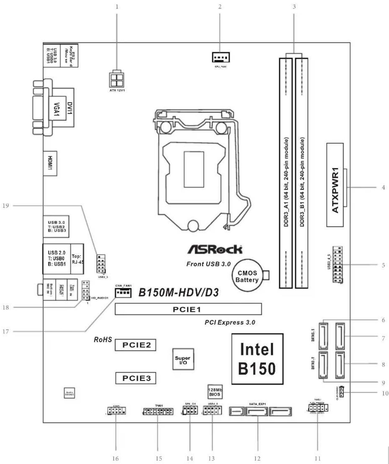
text_image
ASRock Front USB 3.0 B150M-HDV/D3 PCIE1 PCI Express 3.0 RoHS PCIE2 Super I/O PCIE3 Intel B150 128Mb BIOS 16 15 14 13 12 11 1 2 3 4 5 6 7 8 9 10 USB 3.0 T: USB2 B: USB3 USB 2.0 T: USB0 B: USB1 Top: RJ-45 USB2_3 CPU_FAN1 ATX 12V1 ATXPWR1 DDR3_A1 (64 bit, 240-pin module) DDR3_B1 (64 bit, 240-pin module) CMOS BatteryNo. Description
1 ATX 12V Power Connector (ATX12V1)
2 CPU Fan Connector (CPU_FAN1)
3 2 x 240-pin DDR3/DDR3L DIMM Slots (DDR3_A1, DDR3_B1)
4 ATX Power Connector (ATXPWR1)
5 USB 3.0 Header (USB3_4_5)
6 SATA3 Connector (SATA3_2)
7 SATA3 Connector (SATA3_3)
8 SATA3 Connector (SATA3_1)
9 SATA3 Connector (SATA3_0)
10 Clear CMOS Jumper (CLRMOS1)
11 System Panel Header (PANEL1)
12 SATA and SATA Express Connectors (SATA_EXP1)
13 USB 2.0 Header (USB4_5)
14 Chassis Intrusion and Speaker Header (SPK_CI1)
15 TPM Header (TPMS1)
16 COM Port Header (COM1)
17 Chassis Fan Connector (CHA_FAN1)
18 Front Panel Audio Header (HD_AUDIO1)
19 USB 2.0 Header (USB2_3)
I/O Panel
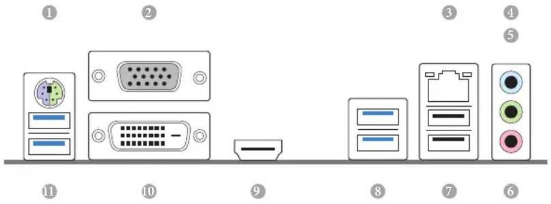
text_image
Diagram showing labeled components of a computer interface with numbered parts from 1 to 11No. Description No. Description
1 PS/2 Mouse/Keyboard Port 7 USB 2.0 Ports (USB01)
2 D-Sub Port 8 USB 3.0 Ports (USB3_23)
3 LAN RJ-45 Port* 9 HDMI Port
4 Line In (Light Blue) ^ 10 DVI-D Port
5 Front Speaker (Lime) ^ 11 USB 3.0 Ports (USB3_01)
6 Microphone (Pink)**
* There are two LEDs on each LAN port. Please refer to the table below for the LAN port LED indications.
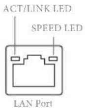
Activity / Link LED Speed LED
| Status | Description | Status | Description |
| Off | No Link | Off | 10Mbps connection |
| Blinking | Data Activity | Orange | 100Mbps connection |
| On | Link | Green | 1Gbps connection |
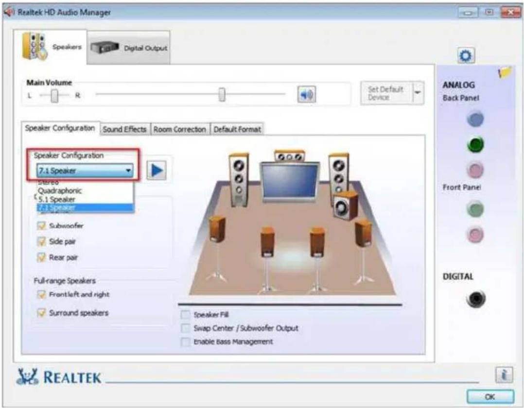
** To configure 7.1 CH HD Audio, it is required to use an HD front panel audio module and enable the multi-channel audio feature through the audio driver.
Please set Speaker Configuration to "7.1 Speaker" in the Realtek HD Audio Manager.
text_image
Realtek HD Audio Manager Speakers Digital Output Main Volume L — R Set Default Device Speaker Configuration Sound Effects Room Correction Default Format Speaker Configuration 7.1 Speaker Stereo Quadraphonic 5.1 Speaker 7.1 Speaker Subwoofer Side pair Rear pair Full-range Speakers Front left and right Surround speakers Speaker Fill Swap Center / Subwoofer Output Enable Bass Management ANALOG Back Panel Front Panel DIGITAL REALTEK OKFunction of the Audio Ports in 7.1-channel Configuration:
| Port Function | |
| Light Blue (Rear panel) Rear Speaker Out | |
| Lime (Rear panel) Front Speaker Out | |
| Pink (Rear panel) Central /Subwoofer Speaker Out | |
| Lime (Front panel) Side Speaker Out | |
1 Introduction
Thank you for purchasing ASRock B150M-HDV/D3 motherboard, a reliable motherboard produced under ASRock's consistently stringent quality control. It delivers excellent performance with robust design conforming to ASRock's commitment to quality and endurance.

Because the motherboard specifications and the BIOS software might be updated, the content of this documentation will be subject to change without notice. In case any modifications of this documentation occur, the updated version will be available on ASRock's website without further notice. If you require technical support related to this motherboard, please visit our website for specific information about the model you are using. You may find the latest VGA cards and CPU support list on ASRock's website as well. ASRock website http://www.asrock.com.
1.1 Package Contents
1.2 Specifications
Platform
CPU
^th Generation Intel ^ Core ^TM i7/i5/i3/Pentium ^ /Celeron ^ Processors (Socket 1151)
Chipset
Memory
buffered memory
Expansion Slot
Graphics
* Intel® HD Graphics Built-in Visuals and the VGA outputs can be supported only with processors which are GPU integrated.
Sync Video with AVC, MVC (S3D) and MPEG-2 Full HW Encode1, Intel ^™ InTru ^TM 3D, Intel ^® Clear Video HD Technology, Intel ^® Insider ^TM , Intel ^® HD Graphics 510/530
independent display controllers
(4096x2304) @ 24Hz
60Hz
HBR (High Bit Rate Audio) with HDMI Port
(Compliant HDMI monitor is required)
and HDMI Ports
Audio
* To configure 7.1 CH HD Audio, it is required to use an HD front panel audio module and enable the multi-channel audio feature through the audio driver.
LAN
Protection)
Rear Panel
I/O
Spike Protection))
Spike Protection))
LED)
Storage
Hot Plug
* Support to be announced
Connector
trol)
ESD Protection (ASRock Full Spike Protection))
ESD Protection (ASRock Full Spike Protection))
BIOS
Feature
port
Multi-adjustment
Hardware
Monitor
CPU temperature)
os
bit
* To install Windows® 7 OS, a modified installation disk with xHCI drivers packed into the ISO file is required. Please refer to page 64 for more detailed instructions.
* For the updated Windows® 10 driver, please visit ASRock's website for details: http://www.asrock.com
Certifications
* For detailed product information, please visit our website: http://www.asrock.com

Please realize that there is a certain risk involved with overclocking, including adjusting the setting in the BIOS, applying Untied Overclocking Technology, or using third-party overclocking tools. Overclocking may affect your system's stability, or even cause damage to the components and devices of your system. It should be done at your own risk and expense. We are not responsible for possible damage caused by overclocking.
1.3 Jumpers Setup
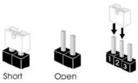
The illustration shows how jumpers are setup. When the jumper cap is placed on the pins, the jumper is "Short". If no jumper cap is placed on the pins, the jumper is "Open". The illustration shows a 3-pin jumper whose pin1 and pin2 are "Short" when a jumper cap is placed on these 2 pins.
text_image
Short OpenClear CMOS Jumper (CLRMOS1)
(see p.1, No. 10)
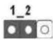
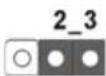
Clear CMOSDefault
CLRMOS1 allows you to clear the data in CMOS. To clear and reset the system parameters to default setup, please turn off the computer and unplug the power cord from the power supply. After waiting for 15 seconds, use a jumper cap to short pin2 and pin3 on CLRMOS1 for 5 seconds. However, please do not clear the CMOS right after you update the BIOS. If you need to clear the CMOS when you just finish updating the BIOS, you must boot up the system first, and then shut it down before you do the clear-CMOS action. Please be noted that the password, date, time, and user default profile will be cleared only if the CMOS battery is removed.

If you clear the CMOS, the case open may be detected. Please adjust the BIOS option "Clear Status" to clear the record of previous chassis intrusion status.
1.4 Onboard Headers and Connectors

Onboard headers and connectors are NOT jumpers. Do NOT place jumper caps over these headers and connectors. Placing jumper caps over the headers and connectors will cause permanent damage to the motherboard.
System Panel Header (9-pin PANEL1) (see p.1, No. 11)
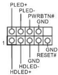
text_image
PLED+ PLED- PWRBTN# GND 1 GND RESET# GND HDLED- HDLED+Connect the power switch, reset switch and system status indicator on the chassis to this header according to the pin assignments below. Note the positive and negative pins before connecting the cables.

PWRBTN (Power Switch):
Connect to the power switch on the chassis front panel. You may configure the way to turn off your system using the power switch.
RESET (Reset Switch):
Connect to the reset switch on the chassis front panel. Press the reset switch to restart the computer if the computer freezes and fails to perform a normal restart.
PLED (System Power LED):
Connect to the power status indicator on the chassis front panel. The LED is on when the system is operating. The LED keeps blinking when the system is in S1/S3 sleep state. The LED is off when the system is in S4 sleep state or powered off (S5).
HDLED (Hard Drive Activity LED):
Connect to the hard drive activity LED on the chassis front panel. The LED is on when the hard drive is reading or writing data.
The front panel design may differ by chassis. A front panel module mainly consists of power switch, reset switch, power LED, hard drive activity LED, speaker and etc. When connecting your chassis front panel module to this header, make sure the wire assignments and the pin assignments are matched correctly.
Chassis Intrusion and
Speaker Header
(7-pin SPK_CI1)
(see p.1, No. 14)
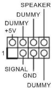
Please connect the chassis intrusion and the chassis speaker to this header.
Serial ATA3 Connectors
(SATA3_0)
(see p.1, No. 9)
(SATA3_1)
(see p.1, No. 8)
(SATA3_2)
(see p.1, No. 6)
(SATA3_3)
(see p.1, No. 7)
(SATA_EXP1)
(see p.1, No. 12)
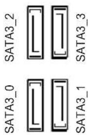
text_image
SATA3_0 SATA3_2 SATA3_3 SATA3_1These six SATA3 connectors support SATA data cables for internal storage devices with up to 6.0 Gb/s data transfer rate.
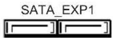
Serial ATA Express
Connector
(SATA_EXP1)
(see p.1, No. 12)
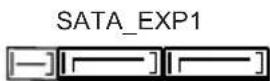
Please connect either SATA or PCIe storage devices to this connector.
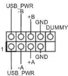
USB 2.0 Headers
(9-pin USB2_3)
(see p.1, No. 19)
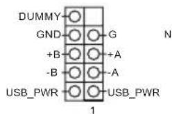
text_image
DUMMY GND +B -B USB_PWR 1 G +A -A USB_PWR NThere are two headers on this motherboard. Each USB 2.0 header can support two ports.
(9-pin USB4_5)
(see p.1, No. 13)
text_image
USB_PWR -B +B GND DUMMY 1 +A GND - A USB_PWRUSB 3.0 Header (19-pin USB3_4_5) (see p.1, No. 5)
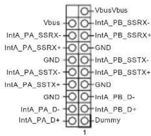
text_image
VbusVbus IntA_PB_SSRX- IntA_PB_SSRX+ GND GND IntA_PB_SSTX- IntA_PB_SSTX+ GND GND IntA_PB_D- IntA_PB_D+ Dummy 1Besides four USB 3.0 ports on the I/O panel, there is one header on this motherboard. Each USB 3.0 header can support two ports.
Front Panel Audio Header (9-pin HD_AUDIO1) (see p.1, No. 18)
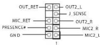
text_image
OUT_RET OUT2_L J_SENSE MIC_RET OUT2_R PRESENCE# MIC2_R GN D MIC2_L 1This header is for connecting audio devices to the front audio panel.

- High Definition Audio supports Jack Sensing, but the panel wire on the chassis must support HDA to function correctly. Please follow the instructions in our manual and chassis manual to install your system.
- If you use an AC'97 audio panel, please install it to the front panel audio header by the steps below:
A. Connect Mic_IN (MIC) to MIC2_L.
B. Connect Audio_R (RIN) to OUT2_R and Audio_L (LIN) to OUT2_L.
C. Connect Ground (GND) to Ground (GND).
D. MIC_RET and OUT_RET are for the HD audio panel only. You don't need to connect them for the AC'97 audio panel.
E. To activate the front mic, go to the "FrontMic" Tab in the Realtek Control panel and adjust "Recording Volume".
Chassis Fan Connector (4-pin CHA_FAN1) (see p.1, No. 17)
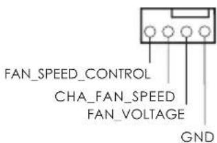
text_image
FAN_SPEED_CONTROL CHA_FAN_SPEED FAN_VOLTAGE GNDPlease connect fan cables to the fan connector and match the black wire to the ground pin.
CPU Fan Connector (4-pin CPU_FAN1) (see p.1, No. 2)
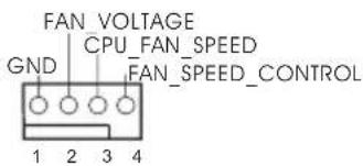
text_image
FAN VOLTAGE GND CPU_FAN_SPEED FAN_SPEED_CONTROL 1 2 3 4This motherboard provides a 4-Pin CPU fan (Quiet Fan) connector. If you plan to connect a 3-Pin CPU fan, please connect it to Pin 1-3.
ATX Power Connector
(24-pin ATXPWR1)
(see p.1, No. 4)
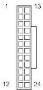
text_image
1 13 12 24This motherboard provides a 24-pin ATX power connector. To use a 20-pin ATX power supply, please plug it along Pin 1 and Pin 13.
ATX 12V Power
Connector
(4-pin ATX12V1)
(see p.1, No. 1)
This motherboard provides a 4-pin ATX 12V power connector.
Serial Port Header
(9-pin COM1)
(see p.1, No. 16)
This COM1 header supports a serial port module.
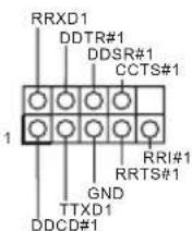
TPM Header
(17-pin TPMS1)
(see p.1, No. 15)
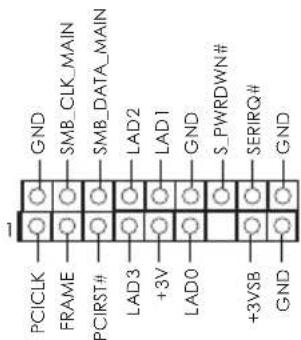
text_image
GND SMB_CLK_MAIN SMB_DATA_MAIN LAD2 LAD1 GND S_PWRDWN# SERIRQ# GND PCICLK FRAME PCIRST# LAD3 +3V LAD0 +3VSB GNDThis connector supports Trusted Platform Module (TPM) system, which can securely store keys, digital certificates, passwords, and data. A TPM system also helps enhance network security, protects digital identities, and ensures platform integrity.
Technische Daten
Plattform
Prozessor
^TM i7/i5/i3/
Pentium ^® /Celeron ^® der 6. Generation (Sockel 1151)
Chipsatz
Speicher
DDR3/DDR3L 1600/1333/1066
1.3/1.2
Fente
d'expansion
Graphiques
1600/1333/1066 Non-ECC Unbuffered
1.3/1.2
Слот
расширения
конфигурация PCIe)
Графическая система
Panel I/O Be- lakang
(ASRock Full Spike Protection))
(ASRock Full Spike Protection))
SPEED LED)
Mikrofon
Penyimpanan
dan Hot Plug
Enabling USB Ports for Windows® 7 Installation
Intel® Braswell and Skylake has removed their support for the Enhanced Host Controller Interface (EHCI – USB2.0) and only kept the eXtensible Host Controller Interface (XHCI – USB3.0). Due to that fact that XHCI is not included in the Windows 7 inbox drivers, users may find it difficult to install Windows 7 operating system because the USB ports on their motherboard won’t work. In order for the USB ports to function properly, please create a Windows® 7 installation disk with the Intel® USB 3.0 eXtensible Host Controller (xHCI) drivers packed into the ISO file.
Requirements
Scenarios
You have an ODD and PS/2 ports:
If there is an optical disc drive, PS/2 ports and PS/2 Keyboard or mouse on your computer, you can skip the instructions below and go ahead to install Windows ^® 7 OS.
You only have an ODD (For Intel Skylake platforms only):
If there is an optical disc drive but no PS/2 ports on your computer, please enable the "PS/2 Simulator" option in UEFI SETUP UTILITY > Advanced > USB Configuration, which allows the USB port to function as a PS/2 port, and then you can install the Windows® 7 OS. Please set PS/S Simulator back to disabled after the installation.
You've got nothing:
If you do not have an optical disc drive, please find another computer and follow the instructions below to create a new ISO file with the “Win7 USB Patcher”. Then use the new patched Windows ^® 7 installation USB drive to install Windows ^® 7 OS.
Instructions
Step 1
Insert the Windows ^® 7 installation disk or USB drive to your system.
Step 2
Extract the tool (Win7 USB Patcher) and launch it.
Step 3
Select the "Win7 Folder" from Step1 by clicking the red circle as shown as the picture below.
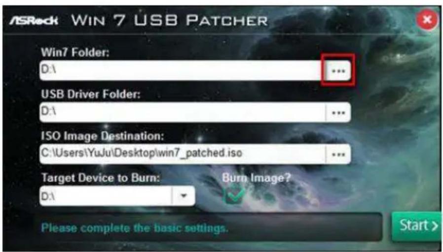
text_image
ASRock WIN 7 USB PATCHER Win7 Folder: D:1 ... USB Driver Folder: D:1 ... ISO Image Destination: C:\Users\YuJu\Desktop\win7_patched.iso ... Target Device to Burn: D:1 Burn Image? Please complete the basic settings. Start >Step 4
Select the "USB Driver Folder" by clicking the red circle as shown as the picture below.
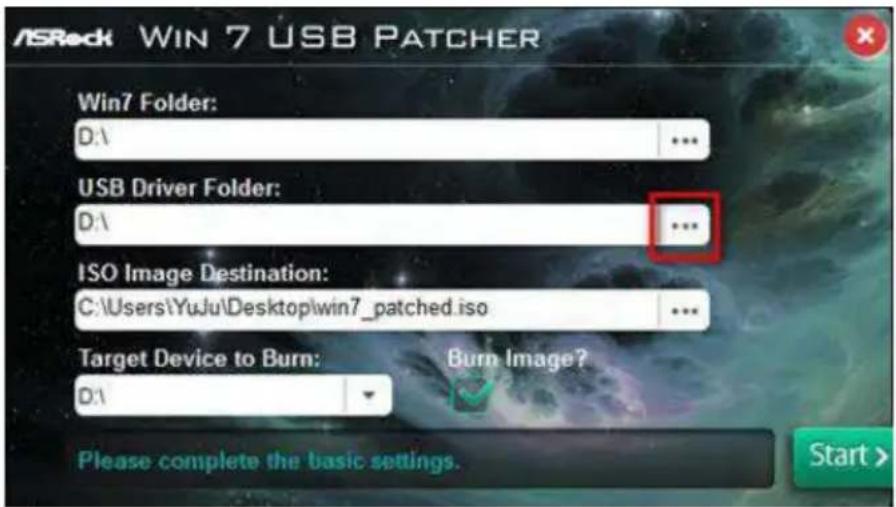
text_image
ASRock WIN 7 USB PATCHER Win7 Folder: D:\ ... USB Driver Folder: D:\ ... ISO Image Destination: C:\Users\YuJu\Desktop\win7_patched.iso ... Target Device to Burn: D:\ Burn Image? Please complete the basic settings. Start >If you are using ASRock's Support CD for the USB 3.0 driver, please select your CD-ROM.
Step 5
Select where to save the ISO file by pressing the red circle as shown as the picture below.
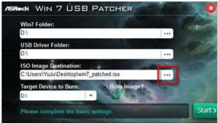
text_image
ASRock WIN 7 USB PATCHER Win7 Folder: D:1 USB Driver Folder: D:1 ISO Image Destination: C:\Users\YuJu\Desktop\win7_patched.iso ... Target Device to Burn: Burn Image? D:1 Please complete the basic settings. Start >Step 6
If you want to burn the patched image to a CD, please check “Burn Image” and select “Target Device to Burn”. If not, the patched ISO image will be exported to the destination selected in Step5. Then Press “Start” to proceed.
Step 7
Now you are able to install Windows ^® 7 on Braswell or Skylake with the new burned CD. Or please use the patched ISO image to make an OS USB drive to install the OS.
Contact Information
If you need to contact ASRock or want to know more about ASRock, you're welcome to visit ASRock's website at http://www.asrock.com; or you may contact your dealer for further information. For technical questions, please submit a support request form at http://www.asrock.com/support/tsd.asp
ASRock Incorporation
2F., No.37, Sec. 2, Jhongyang S. Rd., Beitou District,
Taipei City 112, Taiwan (R.O.C.)
ASRock EUROPE B.V.
Bijsterhuizen 11-11
6546 AR Nijmegen
The Netherlands
Phone: +31-24-345-44-33
Fax: +31-24-345-44-38
ASRock America, Inc.
13848 Magnolia Ave, Chino, CA91710
U.S.A.
Phone: +1-909-590-8308
Fax: +1-909-590-1026