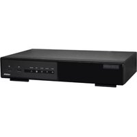
NVR3 - Digital Video Recorder AVtech - Free user manual and instructions
Find the device manual for free NVR3 AVtech in PDF.


User questions about NVR3 AVtech
0 question about this device. Answer the ones you know or ask your own.
Ask a new question about this device
Download the instructions for your Digital Video Recorder in PDF format for free! Find your manual NVR3 - AVtech and take your electronic device back in hand. On this page are published all the documents necessary for the use of your device. NVR3 by AVtech.
USER MANUAL NVR3 AVtech
natural_image
Black-framed image of a 125 video streaming device with a remote control, mouse, and cable (no visible text or symbols)QUICK INSTALLATION GUIDE 3
KORTE HANDLEIDING 12
GUIDE D'INSTALLATION RAPIDE 21
GUÍA RÁPIDA 30
SCHNELLEINSTIEG 39
CE
To all residents of the European Union
Important environmental information about this product

This symbol on the device or the package indicates that disposal of the device after its lifecycle could harm the environment. Do not dispose of the unit (or batteries) as unsorted municipal waste; it should be taken to a specialized company for recycling. This device should be returned to your distributor or to a local recycling service. Respect the local environmental rules.

If in doubt, contact your local waste disposal authorities.
Thank you for choosing Velleman! Please read the manual thoroughly before bringing this device into service. If the device was damaged in transit, don't install or use it and contact your dealer.
Notes
- This document is a Quick installation guide. For more detailed information, refer to the full user manual on the included CD-ROM.
- Product images are for illustrative purposes only. Due to constant product improvements the actual product may differ from the images.
2. Safety Instructions

Keep the device away from children and unauthorised users.

Risk of electroshock when opening the cover. Touching live wires can cause life-threatening electroshocks. Have the device repaired by qualified personnel.

Always disconnect mains power when device not in use or when servicing or maintenance activities are performed. Handle the power cord by the plug only.
3. General Guidelines
Refer to the Velleman® Service and Quality Warranty on the last pages of this manual.


Indoor use only. Keep this device away from rain, moisture, splashing and dripping liquids. Never put objects filled with liquids on top of or close to the device.
Keep this device away from dust and extreme temperatures. Make sure the ventilation openings are clear at all times. For sufficient air circulation, leave at least 1" (± 2.5 cm) in front of the openings.
Protect this device from shocks and abuse. Avoid brute force when operating the device.
- Familiarise yourself with the functions of the device before actually using it.
- All modifications of the device are forbidden for safety reasons. Damage caused by user modifications to the device is not covered by the warranty.
- Only use the device for its intended purpose. Using the device in an unauthorised way will void the warranty.
- Damage caused by disregard of certain guidelines in this manual is not covered by the warranty and the dealer will not accept responsibility for any ensuing defects or problems.
- Keep this manual for future reference.
• DO NOT use this product to violate privacy laws or perform other illegal activities.
4. Features
• high definition recording
• recording throughput: 4 channels
- 1920 x 1080 pixels: 120 IPS, 48 Mbps
• camera power supply & video transmission over Ethernet cable (built-in PoE)
- mobile surveillance via free EagleEyes software on iPhone, iPad, and Android
- mobile phone connection via GPRS, 3G data or Wi-Fi
NVR3
- GUI (Graphical User Interface) display and USB mouse
• high compatibility and offsite backup:
o compatible with all major IP cameras that are ONVIF certified
- works with free Central Management System (CMS) software for offsite backup
- local and remote control completely independent
• HDMI video output resolution up to 1080P
• automatic integrated Dynamic Domain Name Service (DDNS): free service - optional monitor: MONSCA9
- adapter: PAC916T
- HDMI cable: PAC400Tx series and PAC400Gx series
- optional hard disk: HD500GB/S, HD1TB/S, HD2TB/S
- USB mouse: incl.
- IR remote control: incl.
- suitable IP cameras: CAMIP12N, CAMIP16, CAMIP17, CAMIP18, CAMIP19, CAMIP20
- optional router: EM4544, EM4543, EM4571, PCRT1.
5. Installing the Hard Disk Drive (HDD)
Notes:
- It is not recommended to use a green hard disk in this device. For a list of compatible hard disks, please refer to the appendices in the full user manual.
- It is recommended to clear all data on a new hard disk after the DVR is powered on, and to set the date and time correctly to make sure that recorded data are not mixed with older data. For details on clearing all data, refer to the full user manual on the included CD-ROM.
Refer to the illustrations on page 2 of this manual.
- Obtain a suitable hard disk (not included), type SATA (Serial Advanced Technology Attachment). The hard disk must be formatted.
- Make sure to unplug the device from the mains before servicing and do not touch any electronic circuitry to avoid electrostatic discharge.
- Loosen the screws on the top cover of the DVR and open it. Locate the hard disk connector [1] and bracket [2] in the device.
- Make sure the PCB side of the hard disk is facing down, and insert the hard disk into the hard disk connector [1].
- Fasten the hard disk to the bracket [3].
- When the hard disk is installed, close the top cover and fasten it with the screws.
6. Overview
Refer to the illustrations on page 2 of this manual.
| Front panel | |
| ALARM | LED indicator: an alarm event occurs |
| INTERNET | LED indicator: the NVR is connected to internet |
| RECORD | LED indicator: recording is on |
| HDD1 | LED indicator: hard disk is installed in the NVR and connected well |
| e-SATA | LED indicator: an external disk array is connected |
| USB port | Insert a compatible USB flash drive for video backup.Note: For the list of compatible USB flash drives, refer to the full manual on the CD-ROM. |
| mouse port | Insert a mouse (included). |
| Rear panel | |
| eSATA | Connect to a storage device that supports the eSATA interface. For example, an external hard disk or a disk array.Note: Make sure that the disk array supports Linux® to ensure proper functioning. |
| HDMI | Connect to a monitor that supports high-definition video output (HDMI port).Note: Use an appropriate adapter (not incl.) to connect a monitor with VGA or composite connectors. |
| INTERNET (WAN) | Connect to internet via an 8P8C network cable. |
| 1 - 4 (LAN) | Connect to local IP cameras via an 8P8C network cable. The LAN ports support PoE (Power over Ethernet), therefore no power adapters are required for the cameras. |
| On/off switch. Set to I to switch the NVR on. Set to O to switch off. | |
| DC48V IN | Connect to the power supply adapter (incl.). |
7. Connection Diagram
Refer to the illustrations on page 2 of this manual.
Note: This configuration method applies to ETS cameras.
The NVR will automatically configure the IP address of an ETS camera connected by LAN if:
• The default IP configuration method of the camera is DHCP.
• The camera is powered on before the NVR is powered on.
You can connect up to 4 IP cameras.
| A | IP camera | F | Install a HDD in the NVR before connecting it to the IP cameras. |
| B | Alarm I/O + magnetic contact. Refer to the user manual of the IP camera for connection. | G | external hard disk or disk array (eSATA) |
| C | 8P8C network cable | H | HDMI monitor |
| D | remote control | I | IP camera, laptop, iPhone, iPad, Android device, etc. via internet |
| E | on/off switch | J | 48 VDC power adapter |
Connecting the IP Camera (Plug and Play)
- Connect the camera to a LAN port. Make sure the camera is switched on.
- Switch on [E] the NVR.
- Wait until the camera is configured automatically and the images appear on the monitor.
8. User Interface
8.1 NVR Access
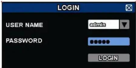
- Connect a USB mouse (included) to the mouse port 📋 on the NVR front panel, and check if there is a mouse icon 📋 on the screen, indicating the USB mouse is detected properly.
- Move your mouse to enter the DVR password with the password keypad. The default user name and password are both admin.
text_image
LOGIN USER NAME admin PASSWORD LOGINThe status will change from 🔒 (key lock) to (unlock).
Note: You can configure four different user levels with different access privileges in the main menu (SYSTEM) > ACCOUNT. For more information, refer to the full user manual on the included CD-ROM.
8.2 Device Status
Note: The functions shown may vary depending on the access user level.
| [WW1H] | key lock |  | key unlock |
 | channel lock |  | channel unlock |
| [KX4Z] | USB flash drive/device connected | [SC9Y] | no USB device connected |
| [084T] | timer recording on |  | timer recording off |
| [BACT] | overwrite on | [3TOP] | overwrite off |
| [SDYK] | sequence mode on | [SSHA] | sequence mode off |
| [YDEX] | PTZ mode on | [WAZ6] | PTZ mode off |
| [VWCB4] | backup event queued, USB flash drive needed |  | USB flash drive full |
 | CPU load | ||
| Network status | |||
 | (WAN) internet connected |  | (WAN) internet disconnected |
| [XYBK] | (WAN) local connection | ||
 | (LAN) auto mode - Mbit/s |  | (LAN) auto mode - Gbit/s |
| [GTBK] | (LAN) DHCP / Static IP mode |  | (LAN) camera disconnected |
Network status
8.3 Channel Status
Note: The functions shown may vary depending on the access user level.
 | auto search on | auto search off | original size | fit to screen | |||
 | live audio on | audio off | audio playback on | audio playback off | |||
 | recording | PTZ control | alarm event | motion event | |||
 | live information | playback information | digital zoom | channel playback | |||
 | quick camera control | ||||||
8.4 Quick Menu Bar
Move the mouse pointer to the left of the screen to extend the quick menu bar and show the functions:
 | Click to show the channel switch panel and select the channel you want. |
 | Click to display the playback control panel, and click play the latest recorded video clip, or click enter the search list. |
 | Click to open the IP search window and check the current connection status of each channel. |
 | Click to show the power off panel to either halt or reboot the system. |
8.5 Main Menu
Right-click anywhere on the screen to open the main menu. Right-click again to exit.
 | QUICK START | Click to set the status display, image settings, and date & time. |
 | SYSTEM | Click to set the system configurations. |
 | EVENT INFORMATION | Click to enter the event search menu. |
 | ADVANCED CONFIG | Click to set CONNECTION, CAMERA, DETECTION, ALERT, NETWORK, DISPLAY, RECORD, & NOTIFY. |
 | SCHEDULE SETTINGS | Click to set record timer and event timer. |
8.6 Playback Panel
 | Fast forward | Increase the speed for fast forward. |
| Fast rewind | Increase the speed for fast rewind. | |
| [34AB] | Play/pause | Click to play the latest recorded video clip immediately, click again to pause.In the pause mode, click ▶nce to get one frame forward, and click ▶get one frame rewind. |
 | Stop | Click to stop the video playback. |
| Slow playback | Click once to get 1/4x speed playback, and click twice to get 1/8x speed playback. | |
 | Previous / next hour | Click to jump to the next/previous time interval in an hour, for example,11:00 - 12:00 or 14:00 - 15:00, and start playing the earliest event video clip recorded during this whole hour. |
 | Quick search | Click to enter the quick search menu. |
| Repeat | Click to set point A and point B in a video clip. The system will play only the specified range in that clip. | |
 | Backup | Click to open the backup menu for video backup. |
8.7 Key Lock / Unlock
To lock or unlock NVR local operation, click 🔍(lock) or (unlock) on the NVR status panel.
When you unlock NVR local operation, the system asks you to enter a user name and password. The default user name and password are both admin. These credentials give you access with the highest user level. For more information, refer to the full user manual on the included CD-ROM.
9. Quick Operation
9.1 Switching on/off and Rebooting
To power off or reboot the NVR:
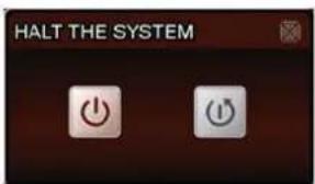
In the quick menu bar, click and then click (power off) or (reboot).
text_image
HALT THE SYSTEM9.2 Viewing a Channel in Full-Screen Mode
To view a channel in full screen mode, you can:
- Click directly on the channel image to see that channel in full screen mode. Double-click the image to restore the previous overview.
- In the quick menu bar, click 📄. On the control panel that appears, select the channel you want to display in full screen mode. Click 📄 to restore the previous overview.
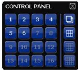
text_image
CONTROL PANEL 1 2 3 4 5 6 7 8 9 10 11 12 13 14 15 169.3 Playing Recorded Video Clips
- Make sure that manual and/or event recording is enabled: in the main menu, select 🔒 (ADVANCED CONFIG) > RECORD to check or adjust the settings.
| ADVANCED CONFIG | ||
| CONNECTION | MANUAL RECORD | ON |
| CAMERA | EVENT RECORD | ON |
| DETECTION | TIMER RECORD | OFF |
| ALERT | PRE-ALARM RECORD | ON |
| NETWORK | OVERWRITE | ON |
| DISPLAY | KEEP DATA LIMIT (DAYS) | OFF |
| RECORD | RECORD CONFIG | SETUP |
| NOTIFY | ||
| EXIT | ||
- In the playback panel, press the play button ▶. The recorded files are shown.
- The fast forward ▶ and fast rewind ▶ buttons increase/decrease the playback speed. Press the button repeatedly to increase/decrease the speed.
- Press the pause button to pause playback.
- Press the stop button ☐ to stop playback and return to live monitoring.
10. Network Configuration
10.1 Configuring the WAN Port
The WAN port connects the NVR to the internet via your router.
- Make sure the WAN port of the NVR is properly connected to the router with an 8P8C network cable.
- From your NVR, in the main menu, select 🔒 (ADVANCED CONFIG) > NETWORK > WAN.
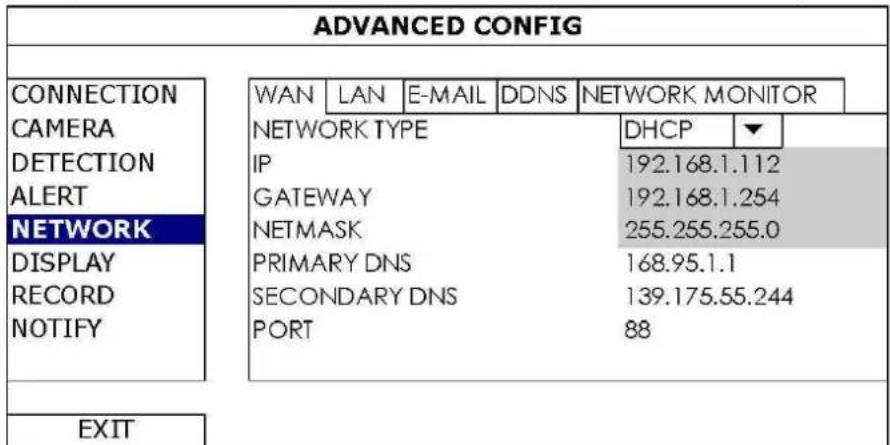
text_image
ADVANCED CONFIG CONNECTION CAMERA DETECTION ALERT NETWORK DISPLAY RECORD NOTIFY WAN LAN E-MAIL DDNS NETWORK MONITOR NETWORK TYPE IP GATEWAY NETMASK PRIMARY DNS SECONDARY DNS PORT DHCP ▼ 192.168.1.112 192.168.1.254 255.255.255.0 168.95.1.1 139.175.55.244 88 EXIT-
If the WAN port is connected to a router (not a hub), you can choose either "DHCP" or "Static" for "NETWORK TYPE".
-
Choose "Static" if you know the network segment of your router.
For example, if your router's IP address is 192.168.0.1, then the network segment is 192.168.0.xx (with xx ranging from 2 to 254).
In this case, you can assign the IP address of the NVR by yourself.
○ Choose "DHCP" if your router supports the DHCP function, and you do not know the network segment of your router.
In this case, the router will automatically assign an IP address to your NVR. -
Configure the DNS setting and port number.
The default port number is 80. Typically, the TCP port used by HTTP is 80. However in some cases, it is better to change this port number for added flexibility or security. - Then, note down the IP address shown in "IP". This is the IP address assigned to your NVR by the router. You'll need it later for port forwarding.
- Click the "DDNS" tab and select "eagleeyes" in "SYSTEM NAME".
- Note down the whole address under "CURRENT HOST ADDRESS", such as MAC000E5318B3F0@ddns.dvrtw.com.tw. This will be the address used to access your NVR remotely.
| ADVANCED CONFIG | |||||
| CONNECTION CAMERA DETECTION ALERT NETWORK DISPLAY RECORD NOTIFY | WAN | LAN | DDNS | ||
| DDNS SYSTEM NAME HOST NAME E-MAIL | ON eagleeyes MAC000E5318B3F0 EMPTY | ||||
| CURRENT HOST ADDRESS EXIT | MAC000E5318B3F0.ddns.dvrtw.com.tw | ||||
-
Select "EXIT" to return to the live view, and continue to the next step for port forwarding.
-
From the web browser of your PC, enter the IP address of your router to access your router.
-
Enter the user name and password if needed.
-
In the router setting interface, go to the port forwarding (or virtual server) rule configuration page. The naming of port forwarding or virtual server may vary based on different router brands. To know where it is, refer to the user manual of your router.
- Enter the NVR IP address and the port number you just noted down and enable this rule.
10.2 Installing the EagleEyes App
Prerequisites
Before installing EagleEyes to your mobile phone for remote surveillance, make sure you have checked the following:
• You have subscribed to and you can access mobile internet services for your mobile phone.
- Note: You might be charged for internet access via wireless or 3G networks. For the internet access rate details, check with your local network operator or service provider.
- You have noted down the IP address, port number, user name and password used to access your network camera from the internet.
Where to download
- Connect to www.eagleeyescctv.com from your mobile device, and sign in.
Please do not try to download EagleEyes from your computer.
-
For Android, select the download link from the website to start downloading.
For iPhone and iPad, two versions of EagleEyes are available: EagleEyesHD Plus (at a fee), and EagleEyesHD Lite (free). -
Select the version you want, and you will be directed to the App Store to download the application.
- When the download is completed, EagleEyes will install automatically to the default location or any location you choose.
For more details about configuring and operating EagleEyes, visit the official website www.avtech.com.tw.
10.3 Configuration
Before configuring push video, make sure:
- The DVR system is set up as described in the chapter Connection in the full manual on the included CD-ROM.
- The DVR is connected to the internet.
- The EagleEyes app is installed on your mobile device (see Installing the EagleEyes App above).
- Open EagleEyes, and add this DVR to the EagleEyes address book. For more details about EagleEyes operation, visit www.eagleeyescctv.com.
11. Push Status
The Push Status functions sends notifications about events to the EagleEyes app on your mobile device. You can select what events you want to be notified about.
Prerequisites
Before using this function, check the following:
• You have iPhone, iPad, or Android™ mobile phone or tablet.
• You have subscribed to and you can access mobile internet services for your mobile phone.
- The mobile app, EagleEyes, is installed in your mobile device. For details, see the section "Installing the EagleEyes" app below.
Configuring the WAN port
- Make sure the NVR is properly connected to a switch with a RJ45 network cable.
- On the NVR, select ADVANCED CONFIG > NETWORK > WAN.
Configuring Push Status
Before configuring push status, make sure that:
- The NVR is set up as described above.
• The NVR is connected to the internet.
On the NVR
- Select ADVANCED CONFIG > NOTIFY > PUSH STATUS.
- Set ACTION to ON.
- Select the system event or events you want to get notified about on your mobile device.
| ADVANCED CONFIG | ||||
| CONNECTION CAMERA DETECTION ALERT NETWORK DISPLAY RECORD NOTIFY PSE MULTICASTING | PUSH STATUS | MESSAGE MAIL | VIDEO MAIL | |
| ACTION | ON | |||
| EVENT | ALL | |||
| VIDEO LOSS | ||||
| HDD FULL | ||||
| POWER ON | ||||
| HDD (CLEAR / NO HDD / OVER TEMPERATURE) | ||||
| NET LOGIN | ||||
| KEY UNLOCK | ||||
| NETWORK | ||||
| UPS | ||||
| SYSTEM ABNORMAL | ||||
| EXIT | ||||
On your mobile device
- Enable Notifications in EagleEyes on your mobile device.
- For details about EagleEyes, refer to the EagleEyes Installation Guide on www.velleman.eu or visit www.eagleeyescctv.com.
Testing
- Try to trigger an alarm event. For example, if you set VIDEO LOSS as an event, disconnect the video to see if you get a push status notification.
12. Technical Specifications
| video compression | H.264 / MPEG4 / MJPEG | ||
| video input | 4 LAN ports with PoE | ||
| video output | HDMI output 1920 x 1080 pixels | ||
| recording mode | manual / timer / motion / alarm | ||
| multiplex operation | live display, record, playback, backup and network | ||
| audio I/O | input via IP camera / no output | ||
| motion detection area | 20 x 15 grid per camera | ||
| pre-alarm recording | yes | ||
| backup device | USB 2.0 backup and network remote backup | ||
| hard disk storage | built-in SATA type | supports 1 x HDD, supported HDD capacity over 4 TB (HDD not incl.) | |
| external eSata | external hard disk or disk array (Linux system support) | ||
| web interface | supports free CMS software (Windows & Mac OS) | ||
| all major internet browsers via Java, QuickTime and VLC plug-in (Internet Explorer, Firefox, Safari, Google Chrome) | |||
| mobile surveillance | EagleEyes software | ||
| smart phones | iPad, iPod touch, iPhone, Android phone & tablet, BlackBerry, Nokia Symbian and Windows Mobile | ||
| computer | CMS (Central Management System) | remote surveillance to monitor up to 20 different IP addresses (Windows & Mac OS) | |
| web browser | Internet Explorer, Firefox, Google Chrome and Safari via Java, QuickTime or VLC plug-in | ||
| remote alarm notification | SMS message, e-mail and image uploading to FTP sites | ||
| network connection | supports TCP/IP, PPPoE, DHCP and DDNS function | ||
| power source | 48 Vdc 1.25 A (incl.) | ||
| power consumption | < 60 W | ||
| operating temperature | 10 °C - 40 °C | ||
| system recovery | system auto recovery after power reconnected | ||
| dimensions | 345 x 59 x 223 mm | ||
Use this device with original accessories only. Velleman nv cannot be held responsible in the event of damage or injury resulting from (incorrect) use of this device. For more info concerning this product and the latest version of this manual, please visit our website www.velleman.eu. The information in this manual is subject to change without prior notice.
All registered trademarks and trade names are properties of their respective owners and are used only for the clarification of the compatibility of our products with the products of the different manufacturers. Windows, Windows Mobile are registered trademarks of Microsoft Corporation in the United States and other countries. iPad, iPod touch, iPhone, iOS are trademarks of Apple Inc., registered in the U.S. and other countries. Android is a trademark of Google Inc. The Trademark BlackBerry® is owned by Research In Motion Limited and is registered in the United States and may be pending or registered in other countries. Velleman NV is not endorsed, sponsored, affiliated with or otherwise authorized by Research In Motion Limited. Symbian is a registered trademark of Symbian Software Ltd, Symbian Ltd. Linux® is the registered trademark of Linus Torvalds in the U.S. and other countries.
© COPYRIGHT NOTICE
The copyright to this manual is owned by Velleman nv. All worldwide rights reserved. No part of this manual may be copied, reproduced, translated or reduced to any electronic medium or otherwise without the prior written consent of the copyright holder.
KORTE HANDLEIDING
1. Inleiding
Connector la caméra IP (Plug and Play)
Velleman® Service and Quality Warranty
Since its foundation in 1972, Velleman® acquired extensive experience in the electronics world and currently distributes its products in over 85 countries.
All our products fulfil strict quality requirements and legal stipulations in the EU. In order to ensure the quality, our products regularly go through an extra quality check, both by an internal quality department and by specialized external organisations. If, all precautionary measures notwithstanding, problems should occur, please make appeal to our warranty (see guarantee conditions).
General Warranty Conditions Concerning Consumer Products (for EU):
- All consumer products are subject to a 24-month warranty on production flaws and defective material as from the original date of purchase.
- Velleman® can decide to replace an article with an equivalent article, or to refund the retail value totally or partially when the complaint is valid and a free repair or replacement of the article is impossible, or if the expenses are out of proportion.
You will be delivered a replacing article or a refund at the value of 100% of the purchase price in case of a flaw occurred in the first year after the date of purchase and delivery, or a replacing article at 50% of the purchase price or a refund at the value of 50% of the retail value in case of a flaw occurred in the second year after the date of purchase and delivery.
- Not covered by warranty:
- all direct or indirect damage caused after delivery to the article (e.g. by oxidation, shocks, falls, dust, dirt, humidity...), and by the article, as well as its contents (e.g. data loss), compensation for loss of profits;
- consumable goods, parts or accessories that are subject to an aging process during normal use, such as batteries (rechargeable, non-rechargeable, built-in or replaceable), lamps, rubber parts, drive belts... (unlimited list);
- flaws resulting from fire, water damage, lightning, accident, natural disaster, etc....;
- flaws caused deliberately, negligently or resulting from improper handling, negligent maintenance, abusive use or use contrary to the manufacturer's instructions;
- damage caused by a commercial, professional or collective use of the article (the warranty validity will be reduced to six (6) months when the article is used professionally);
- damage resulting from an inappropriate packing and shipping of the article;
- all damage caused by modification, repair or alteration performed by a third party without written permission by Velleman®.
- Articles to be repaired must be delivered to your Velleman® dealer, solidly packed (preferably in the original packaging), and be completed with the original receipt of purchase and a clear flaw description.
- Hint: In order to save on cost and time, please reread the manual and check if the flaw is caused by obvious causes prior to presenting the article for repair. Note that returning a non-defective article can also involve handling costs.
• Repairs occurring after warranty expiration are subject to shipping costs.
- The above conditions are without prejudice to all commercial warranties.
The above enumeration is subject to modification according to the article (see article's manual).
NL
Imported for PEREL by Velleman nv
Legen Heirweg 33, 9890 Gavere, Belgium
www.perel.eu