
WR36DA - Screwdriver HiKOKI - Free user manual and instructions
Find the device manual for free WR36DA HiKOKI in PDF.
| Product type | Cordless impact wrench |
| Brand | HiKOKI |
| Model | WR36DA |
| No-load speed (high mode) | 0 – 1,500 /min |
| No-load speed (medium mode) | 0 – 1,200 /min |
| No-load speed (low 2 mode) | 0 – 900 /min |
| No-load speed (low 1 mode) | 0 – 600 /min |
| Capacity (ordinary bolt) | 15/32" (M12) – 1-3/16" (M30) |
| Capacity (high-tensile bolt) | 3/8" (M10) – 15/16" (M24) |
| Max tightening torque | 812 ft-lb (1,100 N·m) |
| Square drive | 3/4" (19 mm) |
| Compatible battery | BSL36B18 (Li-ion 36 V / 18 V) |
| Weight (with battery) | 8.8 lb (4.0 kg) |
| Protection rating | IP56 (dust resistance and water tightness) |
| Lighting | LED with always-on, lock, off modes |
| Functions | Tightening mode selector (4 modes), remaining battery indicator, USB charging, hook |
| Maintenance and cleaning | Clean with a soft cloth and soapy water. Do not use solvents. Check sockets and screws regularly. |
| Safety | Read all safety instructions. Wear eye and hearing protection. Do not use in explosive atmospheres. |
| Spare parts and repairability | Use only metabo HPT spare parts. Have repairs done by an authorized service center. |
| General information | User manual and instruction guide available for download. Storage temperature < 40°C. |
Frequently Asked Questions - WR36DA HiKOKI
User questions about WR36DA HiKOKI
0 question about this device. Answer the ones you know or ask your own.
Ask a new question about this device
Download the instructions for your Screwdriver in PDF format for free! Find your manual WR36DA - HiKOKI and take your electronic device back in hand. On this page are published all the documents necessary for the use of your device. WR36DA by HiKOKI.
USER MANUAL WR36DA HiKOKI
Cordless Impact Wrench
natural_image
Technical illustration of a handheld power tool with visible components and mounting base (no text or symbols)SAFETY INSTRUCTIONS AND INSTRUCTION MANUAL
WARNING
IMPROPER OR UNSAFE use of this power tool can result in death or serious bodily injury! This manual contains important information about product safety. Please read and understand this manual BEFORE operating the power tool. Please keep this manual available for other users and owners before they use the power tool. This manual should be stored in safe place.
INSTRUCTIONS DE SECURITE ET MODE D'EMPLOI
⚠ AVERTISSEMENT
IMPORTANT SAFETY INSTRUCTIONS
Read and understand all of the safety precautions, warnings and operating instructions in the Instruction Manual before operating or maintaining this power tool.
Most accidents that result from power tool operation and maintenance are caused by the failure to observe basic safety rules or precautions. An accident can often be avoided by recognizing a potentially hazardous situation before it occurs, and by observing appropriate safety procedures.
Basic safety precautions are outlined in the “SAFETY” section of this Instruction Manual and in the sections which contain the operation and maintenance instructions.
Hazards that must be avoided to prevent bodily injury or machine damage are identified by WARNINGS on the power tool and in this Instruction Manual.
NEVER use this power tool in a manner that has not been specifically recommended by metabo HPT.
MEANINGS OF SIGNAL WORDS
WARNING indicates a potentially hazardous situations which, if ignored, could result in death or serious injury.
CAUTION indicates a potentially hazardous situations which, if not avoided, may result in minor or moderate injury, or may cause machine damage.
NOTE emphasizes essential information.
SAFETY
GENERAL POWER TOOL SAFETY WARNINGS

WARNING
Read all safety warnings and all instructions.
Failure to follow the warnings and instructions may result in electric shock, fire and/or serious injury.
Save all warnings and instructions for future reference.
The term “power tool” in the warnings refers to your mains-operated (corded) power to (cordless) power tool.
1) Work area safety
a) Keep work area clean and well lit.
Cluttered or dark areas invite accidents.
b) Do not operate power tools in explosive atmospheres, such as in the presence of fl ammable liquids, gases or dust.
Power tools create sparks which may ignite the dust or fumes.
c) Keep children and bystanders away while operating a power tool.
Distractions can cause you to lose control.
2) Electrical safety
a) Power tool plugs must match the outlet.
Never modify the plug in any way.
Do not use any adapter plugs with earthed (grounded) power tools.
Unmodified plugs and matching outlets will reduce risk of electric shock.
b) Avoid body contact with earthed or grounded surfaces such as pipes, radiators, ranges and refrigerators.
There is an increased risk of electric shock if your body is earthed or grounded.
c) Do not expose power tools to rain or wet conditions.
Water entering a power tool will increase the risk of electric shock.
d) Do not abuse the cord. Never use the cord for carrying, pulling or unplugging the power tool.
Keep cord away from heat, oil, sharp edges or moving parts.
Damaged or entangled cords increase the risk of electric shock.
e) When operating a power tool outdoors, use an extension cord suitable for outdoor use.
Use of a cord suitable for outdoor use reduces the risk of electric shock.
f) If operating a power tool in a damp location is unavoidable, use a residual current device (RCD) protected supply.
Use of an RCD reduces the risk of electric shock.
3) Personal safety
a) Stay alert, watch what you are doing and use common sense when operating a power tool. Do not use a power tool while you are tired or under the influence of drugs, alcohol or medication.
A moment of inattention while operating power tools may result in serious personal injury.
b) Use personal protective equipment. Always wear eye protection.
Protective equipment such as dust mask, non-skid safety shoes, hard hat, or hearing protection used for appropriate conditions will reduce personal injuries.
c) Prevent unintentional starting. Ensure the switch is in the off -position before connecting to power source and/or battery pack, picking up or carrying the tool.
Carrying power tools with your finger on the switch or energising power tools that have the switch on invites accidents.
d) Remove any adjusting key or wrench before turning the power tool on.
A wrench or a key left attached to a rotating part of the power tool may result in personal injury.
e) Do not overreach. Keep proper footing and balance at all times.
This enables better control of the power tool in unexpected situations.
f) Dress properly. Do not wear loose clothing or jewellery. Keep your hair, clothing and gloves away from moving parts.
Loose clothes, jewellery or long hair can be caught in moving parts.
g) If devices are provided for the connection of dust extraction and collection facilities, ensure these are connected and properly used.
Use of dust collection can reduce dust-related hazards.
4) Power tool use and care
a) Do not force the power tool. Use the correct power tool for your application.
The correct power tool will do the job better and safer at the rate for which it was designed.
b) Do not use the power tool if the switch does not turn it on and off.
Any power tool that cannot be controlled with the switch is dangerous and must be repaired.
c) Disconnect the plug from the power source and/or the battery pack from the power tool before making any adjustments, changing accessories, or storing power tools.
Such preventive safety measures reduce the risk of starting the power tool accidentally.
d) Store idle power tools out of the reach of children and do not allow persons unfamiliar with the power tool or these instructions to operate the power tool.
Power tools are dangerous in the hands of untrained users.
e) Maintain power tools. Check for misalignment or binding of moving parts, breakage of parts and any other condition that may affect the power tool's operation.
If damaged, have the power tool repaired before use.
Many accidents are caused by poorly maintained power tools.
f) Keep cutting tools sharp and clean.
Properly maintained cutting tools with sharp cutting edges are less likely to bind and are easier to control.
g) Use the power tool, accessories and tool bits etc. in accordance with these instructions, taking into account the working conditions and the work to be performed.
Use of the power tool for operations different from those intended could result in a hazardous situation.
5) Battery tool use and care
a) Recharge only with the charger specified by the manufacturer.
A charger that is suitable for one type of battery pack may create a risk of fire when used with another battery pack.
b) Use power tools only with specifically designated battery packs.
Use of any other battery packs may create a risk of injury and fi re.
c) When battery pack is not in use, keep it away from other metal objects like paper clips, coins, keys, nails, screws, or other small metal objects, that can make a connection from one terminal to another.
Shorting the battery terminals together may cause burns or a fire.
d) Under abusive conditions, liquid may be ejected from the battery; avoid contact. If contact accidentally occurs, flush with water. If liquid contacts eyes, additionally seek medical help.
Liquid ejected from the battery may cause irritation or burns.
6) Service
a) Have your power tool serviced by a qualified repair person using only identical replacement parts.
This will ensure that the safety of the power tool is maintained.
- WARNING -
To reduce the risk of injury, user must read instruction manual.
SPECIFIC SAFETY RULES AND SYMBOLS
- Hold power tools by insulated gripping surfaces, when performing an operation where the fastener may contact hidden wiring.
Fasteners contacting a "live" wire may make exposed metal parts of the power tool "live" and could give the operator an electric shock.
- ALWAYS wear ear protectors when using the tool for extended periods.

Prolonged exposure to high intensity noise can cause hearing loss.
-
NEVER place hands or other body parts near the drill bit or chuck during operation. Hold the impact wrench by its handle only.
-
Because the cordless impact wrench operates by battery power, be aware of the fact that it can begin to operate at any time.
-
When working at elevated locations, clear the area of all other people and be aware of conditions below you.
-
NEVER touch moving parts.
NEVER place your hands, fingers or other body parts near the tool's moving parts.
- NEVER operate without all guards in place.
NEVER operate this tool without all guards or safety features in place and in proper working order. If maintenance or servicing requires the removal of a guard or safety feature, be sure to replace the guard or safety feature before resuming operation of the tool.
- Use right tool.
Don't force small tool or attachment to do the job of a heavy-duty tool.
Don't use tool for purpose not intended —for example— don't use circular saw for cutting tree limbs or logs.
- NEVER use a power tool for applications other than those specified.
NEVER use a power tool for applications other than those specified in the Instruction Manual.
- Handle tool correctly.
Operate the tool according to the instructions provided herein. Do not drop or throw the tool. NEVER allow the tool to be operated by children, individuals unfamiliar with its operation or unauthorized personnel.
- Keep all screws, bolts and covers tightly in place.
Keep all screws, bolts, and plates tightly mounted.
Check their condition periodically.
- Do not use power tools if the plastic housing or handle is cracked.
Cracks in the tool's housing or handle can lead to electric shock. Such tools should not be used until repaired.
- Blades and accessories must be securely mounted to the tool.
Prevent potential injuries to yourself or others. Blades, cutting implements and accessories which have been mounted to the tool should be secure and tight.
- NEVER use a tool which is defective or operating abnormally.
If the tool appears to be operating unusually, making strange noises, or otherwise appears defective, stop using it immediately and arrange for repairs by a metabo HPT authorized service center.
- Carefully handle power tools.
Should a power tool be dropped or struck against hard materials inadvertently, it may be deformed, cracked, or damaged.
- Do not wipe plastic parts with solvent.
Solvents such as gasoline, thinner benzine, carbon tetrachloride, and alcohol may damage and crack plastic parts. Do not wipe them with such solvents.
Wipe plastic parts with a soft cloth lightly dampened with soapy water and dry thoroughly.
- Always wear eye protection that meets the requirement of the latest revision of ANSI Standard Z87.1.
- Do not use the product if the tool or the battery terminals (battery mount) are deformed.
Installing the battery could cause a short circuit that could result in smoke emission or ignition.
- Keep the tool's terminals (battery mount) free of swarf and dust.
○ Prior to use, make sure that swarf and dust have not collected in the area of the terminals.
During use, try to avoid swarf or dust on the tool from falling on the battery.
When suspending operation or after use, do not leave the tool in an area where it may be exposed to falling swarf or dust.
Doing so could cause a short circuit that could result in smoke emission or ignition.
- Definitions for symbols used on this tool
V.....volts
== ....direct current
no ...... no load speed
---/min.... revolutions or reciprocation per minute
IMPORTANT SAFETY INSTRUCTIONS FOR USE OF THE CORDLESS IMPACT WRENCH
WARNING
Death or serious bodily injury could result from improper or unsafe use of the cordless wrench. To avoid these risks, follow these basic safety instructions:
- Never use this impact wrench handle for any application other than those in this manual.
- When working in high places, always make sure that there is no one below before starting to work.
- Always wear eye and ear protection when you work.
- Confirm whether the socket has any crack in it.
- Attach the hex. socket securely onto the anvil. Be sure to fasten the socket with the pin and O-ring before use. If the hex. socket is insufficiently secured, it may drop out and cause an accident. For hex. socket attachment refer to "OPERATION".
- Confirm the tightening torque by a before use in order to ascertain the correct tightening torque to be used.
- If a universal joint is used, be sure not to operate the unit in a no-load condition. Operating in this condition is dangerous. When the socket section spins around it may cause injury to hands or bodies, or the resulting intense vibration may cause the user to drop the tool.
IMPORTANT SAFETY INSTRUCTIONS FOR BATTERY CHARGER
WARNING
Death or serious bodily injury could result from improper or unsafe use of battery chargers. To avoid these risks, follow these basic safety instructions:
READ ALL INSTRUCTIONS
- This manual contains important safety and operating instructions for battery charger Model UC18YSL3.
- Before using battery charger, read all instructions and cautionary markings on (1) battery charger, (2) battery, and (3) product using battery.
Impact: Reduce risk of injury, charge metabo HPT rechargeable battery type BSL36B18 and BSL18 series. Other type of batteries may burst causing personal injury and damage. - Use of an attachment not recommended or sold by the battery charger manufacturer may result in a risk of fire, electric shock, or injury to persons.
- To reduce risk of damage to electric plug and cord, pull by plug when disconnecting battery charger.
- Make sure cord is located so that it will not be stepped on, tripped over, or otherwise subjected to damage or stress.
- An extension cord should not be used unless absolutely necessary. Use of improper extension cord could result in a risk of fire and electric shock.
t o r q u f e W i r s i o n c h d must be used make sure:
a. That blades of extension cord are the same number, size, and shape as those of plug on battery charger:
b. That extension cord is properly wired and in good electrical condition; and
c. That wire size is large enough for a rating of battery charger as specified in Table 1.
Table 1
RECOMMENDED MINIMUM AWG SIZE FOR EXTENSION CORDS FOR BATTERY CHARGERS
| AC Input Rating Amperes* | AWG Size of Cord | ||||
| Equal to or greater than | but less than | Length of Cord, Feet (Meter) | |||
| 25 (7.5) | 50 (15) | 100 (30) | 150 (45) | ||
| 0 | 2 | 18 | 18 | 18 | 16 |
| 2 | 3 | 18 | 18 | 16 | 14 |
| 3 | 4 | 18 | 18 | 16 | 14 |
* If the input rating of a battery charger is given in watts rather than in amperes, the corresponding ampere rating is to be determined by dividing the wattage rating by the voltage rating—for example:
$$ \frac {1 , 2 5 0 \text { watts }}{1 2 5 \text { volts }} = 1 0 \text { amperes } $$
-
Do not operate battery charger with damaged cord or plug-replace them immediately.
-
Do not operate battery charger if it has received a sharp blow, been dropped, or otherwise damaged in any way; take it to a qualified serviceman.
-
Do not disassemble battery charger; take it to a qualified serviceman when service or repair is required. Incorrect reassembly may result in a risk of electric shock or fire.
-
To reduce risk of electric shock, unplug charger from receptacle before attempting any maintenance or cleaning. Removing the battery will not reduce this risk.
IMPORTANT SAFETY INSTRUCTIONS FOR USE OF THE BATTERY AND BATTERY CHARGER
You must charge the battery before you can use the power tool. Before using the model UC18YSL3 battery charger, be sure to read all instructions and cautionary statements on it, the battery and in this manual.
CAUTION
USE ONLY metabo HPT BATTERY TYPE BSL36B18. OTHER TYPES OF BATTERIES MAY BURST AND CAUSE INJURY!
Follow these instructions to avoid the risk of injury:
WARNING
Improper use of the battery or battery charger can lead to serious injury. To avoid these injuries:
- NEVER disassemble the battery.
- NEVER incinerate the battery, even if it is damaged or is completely worn out. The battery can explode in a fire.
- NEVER short-circuit the battery.
- NEVER insert any objects into the battery charger's air vents. Electric shock or damage to the battery charger may result.
- NEVER charge outdoors. Keep the battery away from direct sunlight and use only where there is low humidity and good ventilation.
-
NEVER charge when the temperature is below 14^ F ( -10^ C) or above 104^ F ( 40^ C).
-
NEVER connect two battery chargers together.
- NEVER insert foreign objects into the hole for the battery or the battery charger.
- NEVER use a booster transformer when charging.
- NEVER use DC power to charge.
- NEVER store the battery or battery charger in places where the temperature may reach or exceed 104^ F ( 40^ C) such as inside metal box or car.
- NEVER expose the battery or battery charger to rain or wet conditions.
- ALWAYS operate charger on standard household electrical power (120 volts). Using the charger on any other voltage may overheat and damage the charger.
- ALWAYS wait at least 15 minutes between charges to avoid overheating the charger.
- ALWAYS disconnect the power cord from its receptacle when the charger is not in use.
CAUTION ON LITHIUM-ION BATTERY
To extend the lifetime, the lithium-ion battery equips with the protection function to stop the output.
In the cases of 1 to 3 described below, when using this product, even if you are pulling the switch, the motor may stop. This is not the trouble but the result of protection function.
- When the battery power remaining runs out, the motor stops.
In such case, charge it up immediately. - If the tool is overloaded, the motor may stop. In this case, release the switch of tool and eliminate causes of overloading. After that, you can use it again.
- If the battery is overheated under overload work, the battery power may stop.
In this case, stop using the battery and let the battery cool. After that, you can use it again.
Furthermore, please heed the following warning and caution.
WARNING
In order to prevent any battery leakage, heat generation, smoke emission, explosion and ignition beforehand, please be sure to heed the following precautions.
-
Make sure that swarf and dust do not collect on the battery.
During work make sure that swarf and dust do not fall on the battery.
○ Make sure that any swarf and dust falling on the power tool during work do not collect on the battery.
○ Do not store an unused battery in a location exposed to swarf and dust.
Before storing a battery, remove any swarf and dust that may adhere to it and do not store it together with metal parts (screws, nails, etc.). -
Do not pierce battery with a sharp object such as a nail, strike with a hammer, step on, throw or subject the battery to severe physical shock.
- Do not use an apparently damaged or deformed battery.
- Do not use the battery in reverse polarity.
- Do not connect directly to an electrical outlets or car cigarette lighter sockets.
- Do not use the battery for a purpose other than those specified.
- If the battery charging fails to complete even when a specified recharging time has elapsed, immediately stop further recharging.
- Do not put or subject the battery to high temperatures or high pressure such as into a mic dryer, or high pressure container.
- Keep away from fire immediately when leakage or foul odor are detected.
- Do not use in a location where strong static electricity generates.
- If there is battery leakage, foul odor, heat generated, discolored or deformed, or in any way appears abnormal during use, recharging or storage, immediately remove it from the equipment or battery charger, and stop use.
- Do not immerse the battery or allow any fluids to flow inside. Conductive liquid ingress, such as water, can cause damage resulting in fire or explosion. Store your battery in a cool, dry place, away from combustible and flammable items. Corrosive gas atmospheres must be avoided.
CAUTION
- If liquid leaking from the battery gets into your eyes, do not rub your eyes and wash them well with fresh clean water such as tap water and contact a doctor immediately.
If left untreated, the liquid may cause eye-problems.
- If liquid leaks onto your skin or clothes, wash well with clean water such as tap water immediately.
There is a possibility that this can cause skin irritation.
- If you find rust, foul odor, overheating, discolor, deformation, and/or other irregularities when using the battery for the first time, do not use and return it to your supplier or vendor.
WARNING
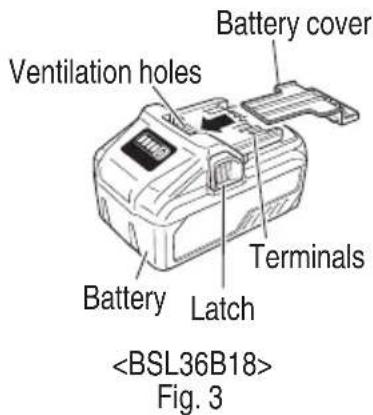
If an electrically conductive foreign object enters the terminals of the lithium ion battery, a short-circuit may occur resulting in the risk of fire. Please observe the following matters when storing the battery.
Do not place electrically conductive cuttings, nails, steel wire, copper wire or other wire in the storage case.
☐ Either install the battery in the power tool or store by securely pressing into the battery cover until the ventilation holes are concealed to prevent short-circuits (See Fig. 3).
REGARDING LITHIUM-ION BATTERY TRANSPORTATION
When transporting a lithium-ion battery, please observe the following precautions.
WARNING
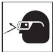
Notify the transporting company that a package contains a lithium-ion battery, inform the company of its power output and follow the instructions of the transportation company when arranging transport.
- Lithium-ion batteries that exceed a power output of 100 Wh are considered to be in the freight classification of Dangerous Goods and will require special application procedures.
- For transportation abroad, you must comply with international law and the rules and regulations of the destination country.
- If the BSL36B18 is installed in the power tool, the power output will exceed 100 Wh and the unit will be classified as Dangerous Goods for freight classification.
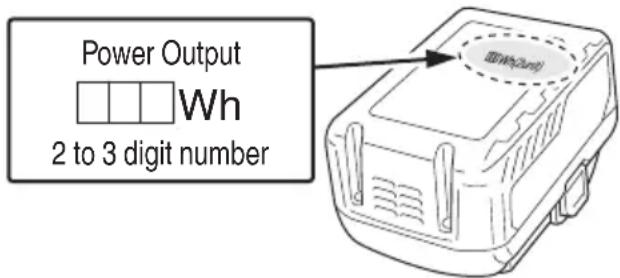
Fig. 1
USB DEVICE CONNECTION PRECAUTIONS
When an unexpected problem occurs, the data in a USB device connected to this product may be corrupted or lost. Always make sure to back up any data contained in USB device prior to use with this product.
Please be aware that our company accepts absolutely no responsibility for any data stored in a USB device that is corrupted or lost, nor for any damage that may occur to a connected device.
PRECAUTIONS REGARDING THE DUST-RESISTANCE AND WATER-PROOFING FUNCTIONS
This product conforms to IP56 protection class ratings (dust-resistance and water-proofing) for electrical equipment as stipulated by the international IEC regulations. (Only the main unit conforms to the IP56 protection class ratings when equipped with a battery.)
[Descriptions of IP Codes] IP56
Protection rating for water penetration Must be no adverse effects on the equipment when sprayed with powerful jets of water from all directions (water-proofed). (100 L of water per minute sprayed for approximately three minutes from a distance of approximately three meters with the use of a spray nozzle with a diameter of 12.5 mm.)
Protection rating for external assault by solid objects Dust that may cause adverse effects on the equipment must not be able to enter (dust-resistance). (The equipment to be left non-operable in a test chamber in which particles of talcum powder with a diameter of less than 75 µm are floating in the air with the use of an agitation pump at a rate of 2 kg per cubic meter for eight hours.)
The equipment has been designed to withstand the effects of dust and water, but there is no guarantee that it will not malfunction. Do not use or leave the equipment in locations where it is subject to excessive amounts of dust, or in locations where it is submerged in water or subject to rainwater.
SAVE THESE INSTRUCTIONS AND MAKE THEM AVAILABLE TO OTHER USERS AND OWNERS OF THIS TOOL!
FUNCTIONAL DESCRIPTION
NOTE
The information contained in this Instruction Manual is designed to assist you in the safe operation and maintenance of the power tool.
NEVER operate, or attempt any maintenance on the tool unless you have first read and understood all safety instructions contained in this manual.
Some illustrations in this Instruction Manual may show details or attachments that differ from those on your own power tool.
NAME OF PARTS
1. Cordless Impact Wrench
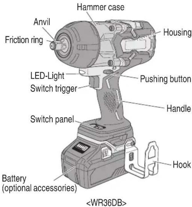
Fig. 2
2. Battery (optional accessories...sold separately) 3.
Battery Charger (optional accessories...sold separately)
SPECIFICATIONS
- Cordless Impact Wrench
| Model WR36DA WR36DB | ||||
| No-load speed | High mode 0 – 1,500 /minMedium mode 0 – 1,200 /minLow 2 mode 0 – 900 /minLow 1 mode 0 – 600 /min | |||
| Capacity | Ordinary bolt 15/32" (M12) – 1-3/16" | (M30) | ||
| High tension bolt 3/8" (M10) – 15/16" | (M24) | |||
| Tightening torque[Tightening is 1-3/16" (M30) F10T][when fully charged at 68°F (20°C) temp.][Tightening time: 3 sec.] | Maximum 812 ft-lbs{1,100 N·m 112.2 kgf·m} | Maximum 775 ft-lbs{1,050 N·m 107.1 kgf·m} | ||
| Square Drive 3/4" (19 mm) 1/2" (12.7 mm) | ||||
| Battery*(optional accessories) | Model | BSL36B18 | ||
| Type | Li-ion battery | |||
| Voltage | DC 36 V / 18V | |||
| Weight | 8.8 lbs. (4.0 kg) | |||
* Existing batteries (BSL3660/3626/3620, BSL18xx and BSL14xx series, etc.) cannot be used with this tool.
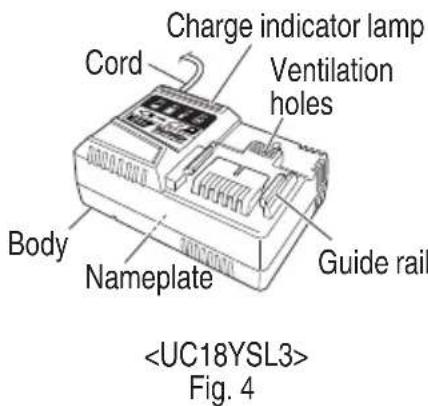
- Battery Charger (optional accessories...sold separately)
| Model | UC18YSL3 |
| Input power source | Single phase: AC 120 V 60 Hz |
| Charging time (At a temperature of 68°F (20°C)) | BSL36B18 : Approx. 52 min |
| Charging voltage | DC 14.4 – 18 V |
| Charging current | DC 8.0 A |
| Weight | 1.3 lbs. (0.6 kg) |
NOTE: The charging time may vary according to temperature and power source voltage.
ASSEMBLY AND OPERATION
APPLICATIONS
○ Tightening and loosening of all types of bolts and nuts, used for securing structural items
REMOVAL AND INSTALLATION METHOD OF BATTERY
- Battery removal
Hold the handle tightly and push the battery latch to remove the battery (see Fig. 5).

CAUTION
Never short-circuit the battery.
- Battery installation
Insert the battery while observing its polarities (see Fig. 5).
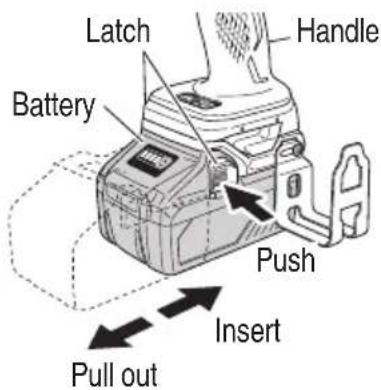
Fig. 5
CHARGING METHOD
NOTE
Before plugging into the receptacle, make sure the following points.
○ The power source voltage is stated on the nameplate.
○ The cord is not damaged.

WARNING
Do not charge at voltage higher than indicated on the nameplate.
If charged at voltage higher than indicated on the nameplate, the charger will burn out.
- Connect the charger's power cord to a receptacle. When the power cord is connected, the charge indicator lamp will blink in red. (At 1-second intervals)

WARNING
Do not use the electrical cord if damaged. Have it immediately.
- Insert the battery to the battery charger.
Firmly Insert the battery into the battery charger as shown in Fig. 6.
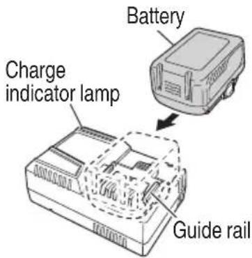
Fig. 6
- Charging
When inserting a battery in the charger, the charge indicator lamp will blink in blue.
When the battery becomes fully recharged, the charge indicator lamp will light up in green.(See Table 2)
(1) Charge indicator lamp indication
The indications of the charge indicator lamp will be as shown in Table 2, according to the condition of the battery charger or the battery.
Table 2
| Indications of the charge indicator lamp | ||||
| Charge indicator lamp (RED / BLUE / GREEN / PURPLE) | Before charging | Blinks (RED) | Lights for 0.5 seconds. Does not light for 0.5 seconds.(off for 0.5 seconds) | Plugged into power source |
| While charging | Blinks (BLUE) | Lights for 0.5 seconds. Does not light for 1 second.(off for 1 second) | Battery capacity at less than 50% | |
| Blinks (BLUE) | Lights for 1 second. Does not light for 0.5 seconds.(off for 0.5 seconds) | Battery capacity at less than 80% | ||
| Lights (BLUE) | Lights continuously | Battery capacity at more than 80% | ||
| Charging complete | Lights (GREEN) | Lights continuously(Continuous buzzer sound: about 6 seconds) | ||
| Overheat standby | Blinks (RED) | Lights for 0.3 seconds. Does not light for 0.3 seconds.(off for 0.3 seconds) | Battery overheated. Unable to charge. (Charging will commence when battery cools) | |
| Charging impossible | Flickers (PURPLE) | Lights for 0.1 seconds. Does not light for 0.1 seconds.(off for 0.1 seconds)(Intermittent buzzer sound: about 2 seconds) | Malfunction in the battery or the charger | |
(2) Regarding the temperature of the rechargeable battery.
The temperatures for rechargeable batteries are as shown in the Table 3, and batteries that have become hot should be cooled for a while before being recharged.
Table 3
| Rechargeable batteries | Temperatures at which the battery can be recharged |
| BSL36B18 | 32^ - 122^ (0^ - 50^) |
(3) Regarding recharging time (At 68°F (20°C))
Table 4 Charging time
| Battery\Charger | UC18YSL3 |
| BSL36B18 Approx. 52 min. | |
NOTE
The recharging time may vary according to the ambient temperature.
- Disconnect battery charger from the receptacle.

CAUTION
Do not pull the plug out of the receptacle by pulling on the cord.
Make sure to grasp the plug when removing from receptacle to avoid damaging cord.
- Remove the battery from the battery charger.
Supporting the battery charger with hand, pull out the battery from the battery charger.
NOTE
Be sure to pull out the battery from the battery charger after use, and then keep it.
Regarding electric discharge in case of new batteries, etc.
As the internal chemical substance of new batteries and batteries that have not been used for an extended period is not activated, the electric discharge might be low when using them the first and second time. This is a temporary phenomenon, and normal time required for recharging will be restored by recharging the batteries 2 – 3 times.
How to make the batteries perform longer
(1) Recharge the batteries before they become completely exhausted.
When you feel that the power of the tool becomes weaker, stop using the tool and recharge its battery. If you continue to use the tool and exhaust the electric current, the battery may be damaged and its life will become shorter.
(2) Avoid recharging at high temperatures.
A rechargeable battery will be hot immediately after use. If such a battery is recharged immediately after use, its internal chemical substance will deteriorate, and the battery life will be shortened. Leave the battery and recharge it after it has cooled for a while.
CAUTION
- When the battery charger has been continuously used, the battery charger will be heated, thus constituting the cause of the failures. Once the charging has been completed, give 15 rest until the next charging.
- If the battery is charged while it is heated because it has been left for a long time in a location subject to direct sunlight or because the battery has just been used, the charge indicator lamp of the charger lights for 0.3 seconds, does not light for 0.3 seconds (off for 0.3 seconds). In such a case, first let the battery cool, then start charging.
- When the charge indicator lamp flickers (at 0.2-second intervals), check for and take out any foreign objects in the charger's battery installation hole. If there are no foreign objects, it is probable that the battery or charger is malfunctioning. Take it to your authorized Service Center.
HOW TO RECHARGE USB DEVICE
When an unexpected problem occurs, the data in a USB device connected to this product may be corrupted or lost. Always make sure to back up any data contained in USB device prior to use with this product.
Please be aware that our company accepts absolutely no responsibility for any data stored in a USB device that is corrupted or lost, nor for any damage that may occur to a connected device.
WARNING
○ Prior to use, check the connecting USB cable for any defect or damage.
Using a defective or damaged USB cable can cause smoke emission or ignition.
○ When the product is not being used, cover the USB port with the rubber cover.
Buildup of dust etc. in the USB port can cause smoke emission or ignition.
NOTE
- The time required for charging will be longer a USB device and battery are being simultaneously charged.
- There may be an occasional pause during USB recharging.
When a USB device is not being charged, turn the USB power switch OFF and remove the USB device from the charger.
Failure to do so may not only reduce the battery life of a USB device, but may also result in unexpected accidents.
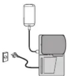
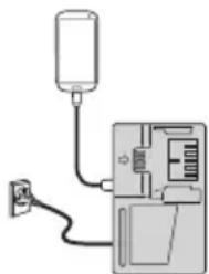
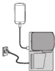
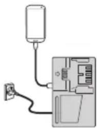
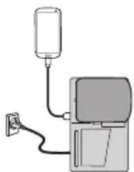
(1) Select a charging method
Depending on the charge method selected, either the battery is inserted into the charger or the power cord is plugged into an outlet.
○ Charging a USB device by battery (Fig. 7-a)
○ Charging a USB device from a electrical outlet (Fig. 7-b)
○ Charging a USB device and battery from a electrical outlet (Fig. 7-c)
natural_image
Simple line drawing of a medical device with a tube and power outlet (no text or symbols)a
natural_image
Simple line drawing of a device with a plug and cable, no text or symbols presentb
natural_image
Simple line drawing of a device with a bulb and cable, no text or symbols presentC
Fig. 7
(2) Turn the USB power switch ON (Fig. 8) When you turn the USB power switch ON, the USB power indicator lamp will light up.
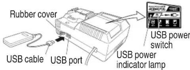
Fig. 8
(3) Connect the USB cable. (Fig. 8) Pull back the rubber cover and firmly plug commercially available USB cable (appropriate to the device being charged) into the USB port.
When the power cord is not plugged into an outlet and the battery runs out of power, power output will stop and the USB power indicator lamp will shut off.
When the USB power indicator lamp goes out, change the battery or plug the power cord into an electrical outlet.
(4) When charging is completed
○ The USB power indicator lamp will not go out when a USB device has been completely charged.
To verify charge status, check the USB device.
○ Turn the USB power switch OFF and unplug the power cord from the electrical outlet. (Fig. 8)
○ Remove the battery from the charger and place the rubber cover over the USB port.
BEFORE USE
Check the work area to make sure that it is clear of debris and clutter.
Clear the area of unnecessary personnel. Ensure that lighting and ventilation is adequate.
OPERATION
-
Selecting the socket matched to the bolt
Be sure to use a socket which is matched to the bolt to be tightened. Using an improper socket will not only result in insufficient tightening but also in damage to the socket or nut.
A worn or deformed hex. or square-holed socket will not give an adequate tightness for fitting to the nut or anvil, consequently resulting in loss of tightening torque.
Pay attention to wear of socket hole, and replace before further wear has developed. -
Installing a socket
Select the socket to be used.
● Pin, O-ring type
(1) Slide the O-ring out of the groove, then align the hole of the socket with the hole of the anvil and insert the anvil into the socket.
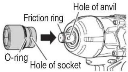
Fig. 9
(2) Insert the pin into the socket.
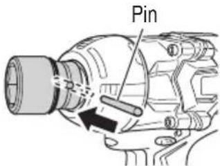
Fig. 10
in a
(3) While making sure that the pin doesn't fall, attach the O-ring to the groove on the socket.
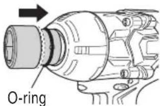
Fig. 11
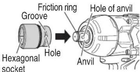
Fig. 12
CAUTION
- Please use the designated attachments which are listed in the operations manual and metabo HPT's catalog. Accidents or injuries could result from not doing so.
● Make sure to firmly install the socket in the anvil. If the socket is not firmly installed it might come out and cause injuries. - When sliding the O-ring out of the groove of the socket, be careful not to drop and lose the pin.
-
(1) Align the square portions of the socket and the anvil with each other.
(2) Make sure to firmly install the socket by pushing it all the way into the anvil.
(3) When removing the socket, pull it out of the anvil.
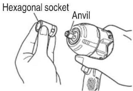
Fig. 13
- Confir rm that the battery is mounted correctly.
- Check the rotational direction
The bit rotates clockwise (viewed from the rear side) by pushing the R-side of the pushing button.
The L-side of the pushing button is pushed to turn the bit counterclockwise. (See Fig. 14). (The (L) and (R) marks are engraved on the body.)
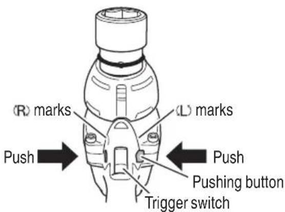
Fig. 14
CAUTION
The pushing button can not be switched while the impact wrench is turning. To switch the pushing button, stop the impact wrench, then set the pushing button.
- Switch operation
When the trigger switch is depressed, the tool rotates. When the trigger is released, the tool stops.
☐ The rotational speed can be controlled by varying the amount that the trigger switch is pulled. Speed is low when the trigger switch is pulled slightly and increases as the trigger switch is pulled more.
When releasing the trigger of the switch, the brake will be applied for immediate stopping.
NOTE
A buzzing noise is produced when the motor is about to rotate; this is only a noise, not a machine failure.
- Tightening and loosening bolts
A hex. socket matching the bolt or nut must first be selected. Then mount the socket on the anvil, and grip the nut to be tightened with the hex. socket. Holding the wrench in line with the bolt, press the power switch to impact the nut for several seconds.
If the nut is only loosely fitted to the bolt, the bolt may turn with the nut, therefore mistaking proper tightening. In this case, stop impact on the nut and hold the bolt head with a wrench before restarting impact, or manually tighten the bolt and nut to prevent them slipping.
- Using the hook
You can use the hook to briefly set aside the tool during operation.
You can change the hook's position to the left or right.
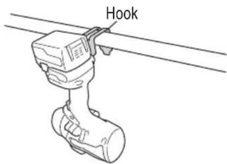
Fig. 15
WARNING
● The hook is not for hanging the tool on your person.
To avoid injury, do not hang the tool from your belt, trousers or any other part of your body.
● Do not use the hook in high places.
Doing so could result in unexpected accidents such as dropping the tool.
- When using the hook, make sure the tool is placed in a stable location where it won't slip off or be dislodged by wind.
CAUTION
Install securely the hook. Unless the hook is securely installed, it may cause an injury while using.
(1) Removing the hook.
Remove the screws fixing the hook with Philips screw driver. (Fig. 16)
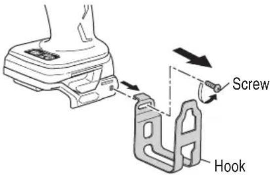
Fig. 16
(2) Replacing the hook and tightening the screws.
Install securely the hook in the groove of power tool and tighten the screws to fix the hook firmly. (Fig. 17)
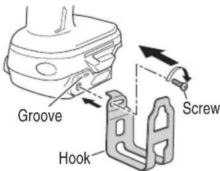
Fig. 17
8. Remaining battery indicator
You can check the battery's remaining capacity by pressing the remaining battery indicator switch to light the indicator lamp. (Fig. 18, Table 4)
The indicator will shut off approximately 3 seconds after the remaining battery indicator switch is pressed.
It is best to use the remaining battery indicator as a guide since there are slight differences such as ambient temperature and the condition of the battery.
Also, the remaining battery indicator may vary from those equipped to a tool or charger.
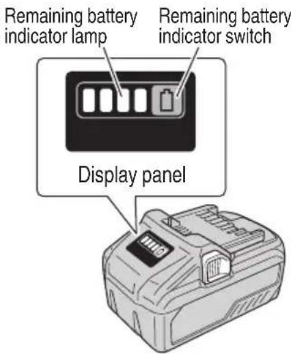
Fig. 18
Table 4
| State of lamp Battery Remaining Power | |
 | Lights;The battery remaining power is over 75%. |
 | Lights;The battery remaining power is 50% - 75%. |
 | Lights;The battery remaining power is 25% - 50%. |
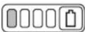 | Lights;The battery remaining power is less than 25%. |
 | Blinks;The battery remaining power is nearly empty. Recharge the battery soonest possible |
 | Blinks;Output suspended due to high temperature. Remove the battery from the tool and allow it to fully cool down. |
 | Blinks;Output suspended due to failure or malfunction. The problem may be the battery so please contact your dealer. |
As the remaining battery indicator shows somewhat differently depending on ambient temperature and battery characteristics, read it as a reference.
NOTE
Do not give a strong shock to the switch panel or break it. It may lead to a trouble.
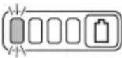
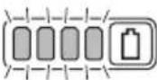
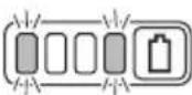
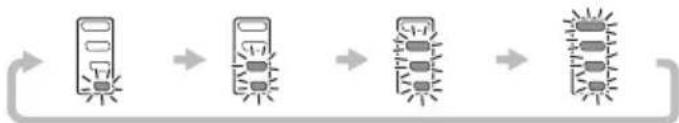
9. How to use the LED light
By pressing the light selector switch on the switch panel, the LED light mode changes as Table 5. It is indicated by green lamp. (Fig. 19)
To prevent the battery power consumption, turn off the LED light frequently.
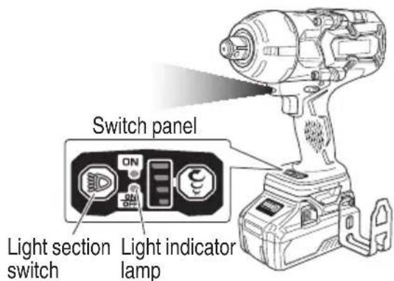
Fig. 19
Table 5
| Always-ON mode | SW interlocked mode | Always-OFF mode | |
| Panel display | 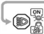 | 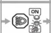 | 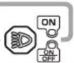 |
| State | Always ON (turn off after 2 minutes) | Light only SW-ON | Always OFF |
CAUTION
- Do not expose directly your eye to the light by looking into the light.
If your eye is continuously exposed to the light, your eye will be hurt.
● Wipe off any dirt or grime attached to the lens of the LED light with a soft cloth, being careful not to scratch the lens.
Scratches on the lens of the LED light can result in decreased brightness.
NOTE
To prevent the battery power consumption caused by forgetting to turn off the LED light, the light goes off automatically in about 2 minutes.
- Tightening mode selector function (Fig. 20)
CAUTION
- Do not subject the switch panel to shock or damage.
- Select tightening mode while the trigger switch is released. Failure to do so could result in malfunction.
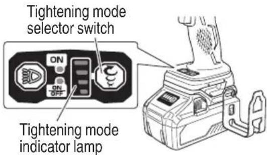
Fig. 20
(1) Tightening mode selector switch
By using the Tightening mode selector switch, the tightening torque can be adjusted according to the type of work.
The Tightening mode switches between 4 different modes each time the Tightening mode selector switch is pressed.
flowchart
graph LR
    A["Input"] --> B["Process Step"]
    B --> C["Output"]
    C --> D["Final Output"]
NOTE
The appropriate mode differs depending on the bolt and the material being screwed. Tighten in a few test bolts and adjust the mode setting accordingly.
The tightening mode selector switch can only be set after the battery has been installed in the wrench and the trigger switch has been pulled once.
Examples of tightening mode selector function settings
| Low 1 mode Low 2 | mode Medium mode High mode | |||
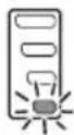 | 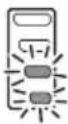 | 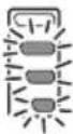 |  | |
| Rotation speed 0 | -600/min 0 - 900/min 0 | -1,200/min 0 - 1,500/min | ||
| Use | For work that requires fi ne adjustments such as when tightening small diameter bolts. | For work that requires the power to be suppressed during tightening. | For work that requires power and speed during tightening. | |
OPERATIONAL CAUTIONS
- Resting the unit after continuous work
After use for continuous bolt-tightening work, rest the unit for 15 minutes or so when replacing the battery. The temperature of the motor, switch, etc., will rise if the work is started again immediately after battery replacement, eventually resulting in burnout.
CAUTION
Do not touch the hammer case as it gets very hot during continuous work.
- Cautions on use of the speed control switch
This switch has a built-in, electronic circuit which steplessly varies the rotation speed. Consequently, when the switch trigger is pulled only slightly (low speed rotation) and the motor is stopped while continuously driving in screws, the components of the electronic circuit parts may overheat and be damaged.
- Work at a tightening torque suitable for the bolt under impact
The optimum tightening torque for nuts or bolts differs with material and size of the nuts or bolts. An excessively large tightening torque for a small bolt may stretch or break the bolt. The tightening torque increases in proportion to the operation time. Use the correct operating time for the bolt.
- Holding the tool
Hold the tool firmly with both hands. In this case hold the tool in line with the bolt.
It is not necessary to push the tool very hard. Hold the tool with a force just sufficient to counteract the impact force.
- Confi rm the tightening torque
The following factors contribute to a reduction of the tightening torque. So confi rm the actual tightening torque needed by screwing up some bolts before the job with a hand torque wrench. Factors affecting the tightening torque are as follows.
(1) Voltage
When the discharge margin is reached, voltage decreases and tightening torque is lowered.
(2) Operating time
The tightening torque increases when the operating time increases. But the tightening torque does not increase above a certain value even if the tool is driven for a long time.
(3) Diameter of bolt
The tightening torque differs with the diameter of the bolt. Generally a larger diameter bolt requires larger tightening torque.
(4) Tightening conditions
The tightening torque differs according to the torque ratio; class, and length of bolts even when bolts with the same size threads are used. The tightening torque also differs according to the condition of the surface of workpiece through which the bolts are to be tightened. When the bolt and nut turn together, torque is greatly reduced.
(5) Using optional parts
The tightening torque is reduced a little when an extension bar, universal joint or a long socket is used.
(6) Clearance of the socket
A worn or deformed hex. or a square-holed socket will not give an adequate tightness to the fitting between the nut or anvil, consequently resulting in loss of tightening torque.
Using an improper socket which does not match to the bolt will result in an insufficient tightening torque.
(7) Tightening torque varies, depending on the battery's charge level.
MAINTENANCE AND INSPECTION
⚠️ CAUTION: Pull out battery before doing any inspection or maintenance.
- Checking the condition of the socket
A worn or deformed hex. or a square-holed socket will not give an adequate tightness to the fitting between the nut or anvil, consequently resulting in loss of tightening torque. Pay attention to wear of a socket holes periodically, and replace with a new one if needed.
- Check the Screws
Loose screws are dangerous. Regularly inspect them and make sure they are tight.
CAUTION
Using this power tool with loosened screws may be recovered by repeatedly charging and using extremely dangerous.
- Maintenance of the motor
The motor unit winding is the very "heart" of the power tool. Exercise due care to ensure the winding does not become damaged and/or wet with oil or water.
- Check for Dust
Dust may be removed with a soft cloth or a cloth dampened with soapy water.
Do not use bleach, chlorine, gasoline or thinner, for they may damage the plastics.
- Inspection of terminals (tool and battery)
Check to make sure that swarf and dust have not collected on the terminals.
On occasion check prior, during and after operation.
CAUTION
Remove any swarf or dust which may have collected on the terminals.
Failure to do so may result in malfunction.
- Disposal of the exhausted battery
WARNING
Do not dispose of the exhausted battery. The battery must explode if it is incinerated. The product that you have purchased contains a rechargeable battery. The battery is recyclable. At the end of it's useful life, under various state and local laws, it may be illegal to dispose of this battery into the municipal waste stream. Check with your local solid waste offi cials for details in your area for recycling options or proper disposal.
- Storage
Storing in a place below 104^ F ( 40^ C) and out of the reach of children.
NOTE
Storing lithium-ion batteries
Make sure the lithium-ion batteries have been fully charged before storing them. Prolonged storage (3 months or more) of batteries with a low charge may result in performance deterioration, significantly reducing battery usage time or rendering the batteries incapable of holding a charge.
However, significantly reduced battery usage time snays be recovered by repeatedly charging and using the batteries two to five times.
If the battery usage time is extremely short despite repeated charging and use, consider the batteries dead and purchase new batteries.
- Service and repairs
All quality power tools will eventually require servicing or replacement of parts because of wear from normal use. To assure that only authorized replacement parts will be used, all service and repairs must be performed by a metabo HPT AUTHORIZED SERVICE CENTER, ONLY.
CAUTION
In the operation and maintenance of power tools, the safety regulations and standards prescribed in each country must be observed.
Important notice on the batteries for the metabo HPT cordless power tools
Please always use one of our designated genuine batteries. We cannot guarantee the safety and performance of our cordless power tool when used with batteries other than these designated by us, or when the battery is disassembled and modified (such as disassembly and replacement of cells or other internal parts).
TROUBLESHOOTING GUIDE
WARNING
● To avoid injury from an accidental start, turn the switch OFF and remove the plug from the power source or remove the battery from the main body before making any adjustments.
● All electrical or mechanical repairs should be done only by qualified service technicians. Contact metabo HPT Authorized Service Center.
- Power tool
| Problem Possible | Cause Possible Solution | |
| Tool doesn’t run No remaining battery power Charge the battery. | ||
| Tool suddenly stopped Tool was overburdened Get rid of the problem causing the overburden. | ||
| The battery is overheated. | Let the battery cool down. | |
| The trigger switch was held down for 5 minutes or more. | This is not a malfunction.The motor was automatically stopped to prevent failure of the tool. | |
| Tool sockets-can’t be attached-fall off-can’t be removed | The shape of the attachment portion doesn’t match | Make sure to use sockets with the appropriate square drive size.WR36DA: 19 mmWR36DB: 12.7 mm |
| Switch can’t be pulled | Forward/reverse selector button is positioned halfway | Press the button firmly into position for the desired direction of rotation. |
| An abnormal high-pitched noise occurs when the trigger switch is pulled. | The trigger switch is being pulled only slightly. | This is not a malfunction.It does not occur if the trigger switch is pulled more fully. |
| Battery cannot be installed | Attempting to install a battery other than that specified for the tool. | Please install a multi volt type battery. |
- Charger
| Symptom | Possible cause | Remedy |
| The charge indicator lamp is rapidly flickers purple, and battery charging doesn’t begin. | The battery is not inserted all the way. | Insert the battery firmly. |
| There is foreign matter in the battery terminal or where the battery is attached. | Remove the foreign matter. | |
| The charge indicator lamp blinks red, and battery charging doesn’t begin. | The battery is not inserted all the way. | Insert the battery firmly. |
| The battery is overheated. | If left alone, the battery will automatically begin charging if its temperature decreases, but this may reduce battery life. It is recommended that the battery be cooled in a well-ventilated location away from direct sunlight before charging it. | |
| Battery usage time is short even though the battery is fully charged. | The battery’s life is depleted. | Replace the battery with a new one. |
| Symptom Possible | cause Remedy | |
| The battery takes a long time to charge. | The temperature of the battery, the charger, or the surrounding environment is extremely low. | Charge the battery indoors or in another warmer environment. |
| The charger's vents are blocked, causing its internal components to overheat. | Avoid blocking the vents. | |
| The cooling fan is not running. Contact a metabo HPT Authorized Service Center for repairs. | ||
| The USB power lamp has switched off and the USB device has stopped charging. | The battery's capacity has become low. Replace the battery with one that has capacity remaining. | |
| USB power lamp does not switch off even though the USB device has finished charging. | The USB power lamp lights up green to indicate that USB charging is possible. | This is not a malfunction. |
| It is unclear what the charging status of a USB device is, or whether its charging is complete. | The USB power lamp does not switch off even when charging is complete. | Examine the USB device that is charging to confi rm its charging status. |
| Charging of a USB device pauses midway. | The charger was plugged into an electrical socket while the USB device was being charged using the battery as the power source. | This is not a malfunction.The charger pauses USB charging for about 5 seconds when it is diff erentiating between power sources. |
| A battery was inserted into the charger while the USB device was being charged using a power socket as the power source. | ||
| Charging of the USB device pauses midway when the battery and the USB device are being charged at the same time. | The battery has become fully charged. This is not a malfunction.The charger pauses USB charging for about 5 seconds while it checks whether the battery has successfully completed charging. | |
| Charging of the USB device doesn't start when the battery and the USB device are being charged at the same time. | The remaining battery capacity is extremely low. | This is not a malfunction.When the battery capacity reaches a certain level, USB charging automatically begins. |
ACCESSORIES
WARNING
ALWAYS use Only authorized metabo HPT replacement parts and accessories. NEVER use replacement parts or accessories which are not intended for use with this tool. Contact metabo HPT if you are not sure whether it is safe to use a particular replacement part or accessory with your tool.
The use of any other attachment or accessory can be dangerous and could cause injury or mechanical damage.
NOTE
Accessories are subject to change without any obligation on the part of the metabo HPT.
STANDARD ACCESSORIES
| WR36DA/WR36DB(NN) | Battery, battery charger, plastic case and battery cover are not contained. |
OPTIONAL ACCESSORIES
- Battery (BSL36B18)
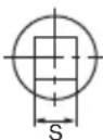
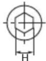
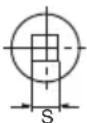
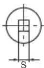
- Sockets
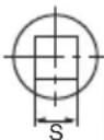
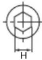
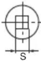
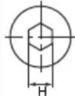
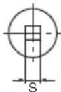
| Square head drive dimensions S | Part Name Code No. | Suitable Bolt Diameter | Hexagonal width across fl ats H | Form | Main Socket Dimensions | ||||||
| High tension | ISO (ordinary) | ISO (small) | Inch bolts | L | L | 1 | |||||
| 1/2"(12.7 mm) | Hexagonal Socket | 17 mm 873536 | M10 | M12 | W3/8" | 11/16"(17 mm) | C | 1-1/4"(32 mm) | 5/16"(8 mm) | 1-3/32"(28 mm) | |
| 19 mm 873624 | M12 | M14 | W7/16" | 3/4"(19 mm) | C | 1-11/32"(34 mm) | 11/32"(9 mm) | 1-3/32"(28 mm) | |||
| 21 mm 873626 | W1/2" | 13/16"(21 mm) | D | 1-13/32"(36 mm) | 3/8"(10 mm) | 1-1/4"(32 mm) | |||||
| 22 mm | 873627 | M12 | M14 | M16 | 7/8"(22 mm) | D | 1-9/16"(40 mm) | 9/16"(14 mm) | |||
| 24 mm | 873629 | M16 | M18 | 15/16"(24 mm) | D | 1-9/16"(40 mm) | 9/16"(15 mm) | ||||
| 26 mm | 873630 | W5/8" | 1-1/32"(26 mm) | D | 1-9/16"(40 mm) | 9/16"(15 mm) | |||||
| 27 mm | 985195 | M16 | M18 | M20 | 1-1/16"(27 mm) | D | 1-9/16"(40 mm) | 11/16"(17 mm) | |||
| 30 mm23 mm 87 | 9851964527 M14 W9/16" | M20 | M22 | 15/16" (23 mm) | 1-3/16"(30 mm)C | D2-11/64" (55 mm) | 1-31/32"(50 mm)19/32" (15 mm) | 3/4"(19 mm)1-1/2" (38 mm) | |||
| 3/4" (19 mm) | Hexagonal Socket | ||||||||||
| 24 mm 87 | 4528 M16 M18 | 15/16" (24 mm) | D | 1-9/16" (40 mm) | |||||||
| 26 mm 87 | 4529 M16 W5/8" | 1-1/32" (26 mm) | 5/8" (16 mm) | 1-21/32" (42 mm) | |||||||
| 27 mm 87 | 4530 M16 M18 M20 | 1-1/16" (27 mm) | 1-11/16" (43 mm) | ||||||||
| 30 mm | 874532 | M20 | M22 | 1-3/16" (30 mm) | 3/4" (19 mm) | 1-27/32" (47 mm) | |||||
| 32 mm | 874523 | M20 | M22 | M24 | W3/4" | 1-1/4" (32 mm) | 1-31/32" (50 mm) | ||||
| 35 mm | 874533 | W7/8" | 1-3/8" (35 mm) | 2-3/64" (52 mm) | |||||||
| 36 mm | 874534 M22 | M24 | M27 | 1-7/16" (36 mm) | 2-11/64" (55 mm) | ||||||
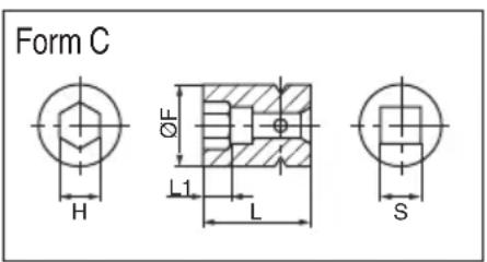
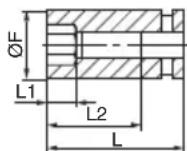
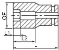
3. Long Socket
Form B
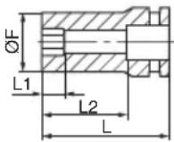
Form C

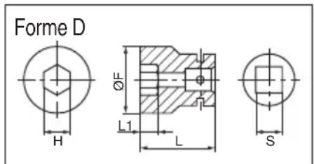
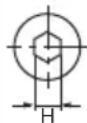
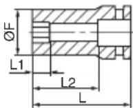
Form D

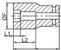
| Square head drive dimensions S | Part Name Code No. | Suitable Bolt Diameter | Hexagonal width across fl ats H | Form | Main Socket Dimensions | |||||||
| High tension | ISO (ordinary) | ISO (small) | Inch bolts | L | L1 | L2 | øF | |||||
| 1/2" (12.7 mm) | Long Socket | 17 mm | 955141 | M10 | M12 W3/8" | 11/16" (17 mm) | B | 2-3/64" (52 mm) | 15/16" (24 mm) | 1-11/32" (34 mm) | 1" (25 mm) | |
| 17 mm | 955149 | M10 | M12 W3/8" | 11/16" (17 mm) | B | 2-15/16" (75 mm) | 15/16" (24 mm) | 2-1/4" (57 mm) | 1" (25 mm) | |||
| 19 mm | 955142 | M12 | M14 | W7/16" | 3/4" (19 mm) | B | 2-3/64" (52 mm) | 15/16" (24 mm) | 1-11/32" (34 mm) | |||
| 19 mm | 955150 | M12 | M14 | W7/16" | 3/4" (19 mm) | B | 2-15/16" (75 mm) | 15/16" (24 mm) | 1-3/32" (28 mm) | |||
| 21 mm | 955143 | W1/2" | 13/16" (21 mm) | D | 2-3/64" (52 mm) | 15/16" (24 mm) | 1-7/32" (31 mm) | |||||
| 21 mm | 955151 | W1/2" | 13/16" (21 mm) | D | 2-15/16" (75 mm) | 15/16" (24 mm) | 1-7/32" (31 mm) | |||||
| 21 mm | 991480 | W1/2" | 13/16" (21 mm) | D | 4-15/16" (125 mm) | 15/16" (24 mm) | 1-7/32" (31 mm) | |||||
| 22 mm | 955144 | M12 | M14 | M16 | 7/8" (22 mm) | D | 2-3/64" (52 mm) | 15/16" (24 mm) | 1-9/32" (32.5 mm) | |||
| 24 mm | 955146 | M16 | M18 | 15/16" (24 mm) | D | 2-3/64" (52 mm) | 1" (25 mm) | 1-11/32" (34 mm) | ||||
| 26 mm | 955147 | W5/8" | 1-1/32" (26 mm) | D | 2-15/16" (75 mm) | 1" (25 mm) | 1-1/2" (38 mm) | |||||
| 30 mm | 985197 | M20 | M22 | 1-3/16" (30 mm) | D | 2-15/16" (75 mm) | 1" (25 mm) | 1-21/32" (42 mm) | ||||
| 3/4" (19 mm) | Long Socket | 24 mm | 955033 | M18 | 15/16" (24 mm) | B | 2-23/64" (60 mm) | 29/32" (23 mm) | 1-11/32" (32 mm) | |||
| 26 mm | 955034 | W5/8" | 1-1/32" (26 mm) | C | 3-11/32" (85 mm) | 1" (25 mm) | 1-1/2" (38 mm) | |||||
| 27 mm | 955035 | M16 | M18 M20 | 1-1/16" (27 mm) | D | 1-1/32" (26 mm) | 1-17/32" (39 mm) | |||||
| 30 mm | 955037 | M20 | M22 | 1-3/16" (30 mm) | 1-11/16" (43 mm) | |||||||
| 32 mm | 955038 | M20 | M22 | M24 | W3/4" | 1-1/4" (32 mm) | 3-15/16" (100 mm) | 1-13/16" (46 mm) | ||||
| 36 mm | 955092 | M22 M24 | M27 | 1-7/16" (36 mm) | 2-11/64" (55 mm) | |||||||
4. Extension bar:
The extension bar is convenient for working in very restricted spaces or when the socket provided cannot reach the bolt to be tightened.
CAUTION
When the extension bar is used, the tightening torque is reduced slightly compared with the ordinary socket.
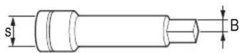
| Code No. Dimention B, S | |
| 873633 1/2" (12.7 mm) | |
| 874535 3/4" (19 mm) |
5. Universal joint:
The universal joint is convenient for impacting nuts when there is an angle between the socket and wrench, or when working in a very narrow space.
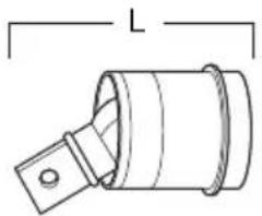
natural_image
Technical line drawing of a cylindrical mechanical component with a flanged end and a central slot (no text or symbols)| Code No. L | |
| 986062 58 mm | |
| 955088 106 mm |
NOTE
Specifications are subject to change without any obligaiton on the part of the metabo HPT.
CONSIGNES DE SÉCURITÉ IMPORTANTES
● Broche, type joint torique
Fig. 11
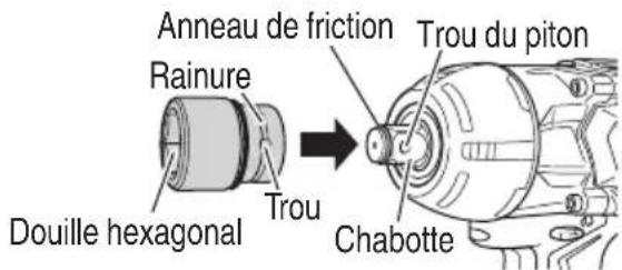
Fig. 12
PRECAUTION
| Dimensions de l'entraînement carré S | Nom du produit | N° de Code | Diamètre de boulon adéquat | Largeur hexagonale mesurée aux bords H | Forme | Douille principale Dimensions | ||||||
| Haute tension | ISO (ordinaire) | ISO (réduit) | Boulons en pouces | L | L | 1 | ||||||
| 1/2 " (12.7 mm) | Douille hexagonale | 17 mm 873536 | M10 | M12 | W3/8" | 11/16"(17 mm) | C | 1-1/4"(32 mm) | 5/16"(8 mm) | 1-3/32"(28 mm) | ||
| 19 mm 873624 | M12 | M14 | W7/16" | 3/4"(19 mm) | C | 1-11/32"(34 mm) | 11/32"(9 mm) | 1-3/32"(28 mm) | ||||
| 21 mm 873626 | W1/2" | 13/16"(21 mm) | D | 1-13/32"(36 mm) | 3/8"(10 mm) | 1-1/4"(32 mm) | ||||||
| 22 mm | 873627 | M12 | M14 | M16 | 7/8"(22 mm) | D | 1-9/16"(40 mm) | 9/16"(14 mm) | 1-3/8"(35 mm) | |||
| 24 mm | 873629 | M16 | M18 | 15/16"(24 mm) | D | 1-9/16"(40 mm) | 9/16"(15 mm) | 1-1/2"(38 mm) | ||||
| 26 mm | 873630 | W5/8" | 1-1/32"(26 mm) | D | 1-9/16"(40 mm) | 9/16"(15 mm) | 1-1/2"(38 mm) | |||||
| 27 mm | 985195 | M16 | M18 | M20 | 1-1/16"(27 mm) | D | 1-9/16"(40 mm) | 11/16"(17 mm) | 1-21/32"(42 mm) | |||
| 30 mm | 985196 | M20 | M22 | 1-3/16"(30 mm) | D | 1-31/32"(50 mm) | 3/4"(19 mm) | 1-21/32"(42 mm) | ||||
0
| Dimensions de l'entraînement carré S | Nom du produit | N° de Code | Diamètre de boulon adéquat | Largeur hexagonale mesurée aux bords H | Forme | Douille principale Dimensions | ||||||
| Haute tension | ISO (ordinaire) | ISO (réduit) | Boulons en pouces | L | L | 1 | ||||||
| 3/4" (19 mm) | Douille hexagonale | 23 mm 87 | 4527 M14 W9/16" | 15/16" (23 mm) | C | 2-11/64" (55 mm) | 19/32" (15 mm) | 1-1/2" (38 mm) | ||||
| 24 mm 87 | 4528 M16 M18 | 15/16" (24 mm) | D | 1-9/16" (40 mm) | ||||||||
| 26 mm 87 | 4529 M16 W5/8" | 1-1/32" (26 mm) | 5/8" (16 mm) | 1-21/32" (42 mm) | ||||||||
| 27 mm 87 | 4530 M16 M18 M20 | 1-1/16" (27 mm) | 1-11/16" (43 mm) | |||||||||
| 30 mm 87 | 4532 | M20 | M22 | 1-3/16" (30 mm) | 3/4" (19 mm) | 1-27/32" (47 mm) | ||||||
| 32 mm 87 | 4523 M20 | M22 M24 W3/4" | 1-1/4" (32 mm) | 1-31/32" (50 mm) | ||||||||
| 35 mm 87 | 4533 | W7/8" | 1-3/8" (35 mm) | 2-3/64" (52 mm) | ||||||||
| 36 mm 87 | 4534 M22 | M24 M27 | 1-7/16" (36 mm) | 2-11/64" (55 mm) | ||||||||
3. Douille longue
Forme B
Forme C
Forme D
| Dimensions de l'entraînement carré S | Nom du produit | N° de Code | Diamètre de boulon adéquat | Largeur hexagonale mesurée aux bords H | Forme | Douille principale Dimensions | |||||||
| Haute tension | ISO (ordinaire) | ISO (réduit) | Boulons en pouces | L | L1 | L2 | øF | ||||||
| 1/2" (12.7 mm) | Douille longue | 17 mm | 955141 | M10 | M12 | W3/8" | 11/16" (17 mm) | B | 2-3/64" (52 mm) | 15/16" (24 mm) | 1-11/32" (34 mm) | 1" (25 mm) | |
| 17 mm | 955149 | M10 | M12 | W3/8" | 11/16" (17 mm) | B | 2-15/16" (75 mm) | 15/16" (24 mm) | 2-1/4" (57 mm) | 1" (25 mm) | |||
| 19 mm | 955142 | M12 M14 | W7/16" | 3/4" (19 mm) | B | 2-3/64" (52 mm) | 15/16" (24 mm) | 1-11/32" (34 mm) | 1-3/32" (28 mm) | ||||
| 19 mm | 955150 | M12 | M14 | W7/16" | 3/4" (19 mm) | B | 2-15/16" (75 mm) | 15/16" (24 mm) | 2-1/4" (57 mm) | 1-3/32" (28 mm) | |||
| 21 mm | 955143 | W1/2" | 13/16" (21 mm) | D | 2-3/64" (52 mm) | 15/16" (24 mm) | 1-11/32" (34 mm) | 1-7/32" (31 mm) | |||||
| 21 mm | 955151 | W1/2" | 13/16" (21 mm) | D | 2-15/16" (75 mm) | 15/16" (24 mm) | 2-1/4" (57 mm) | 1-7/32" (31 mm) | |||||
| 21 mm | 991480 | W1/2" | 13/16" (21 mm) | D | 4-15/16" (125 mm) | 15/16" (24 mm) | 4-7/32" (107 mm) | 1-7/32" (31 mm) | |||||
| 22 mm | 955144 | M12 | M14 M16 | 7/8" (22 mm) | D | 2-3/64" (52 mm) | 15/16" (24 mm) | 1-11/32" (34 mm) | 1-9/32" (32.5 mm) | ||||
| 24 mm | 955146 | M16 M18 | 15/16" (24 mm) | D | 2-3/64" (52 mm) | 1" (25 mm) | 1-11/32" (34 mm) | 1-11/32" (34 mm) | |||||
| 26 mm | 955147 | W5/8" | 1-1/32" (26 mm) | D | 2-15/16" (75 mm) | 1" (25 mm) | 2-1/4" (57 mm) | 1-1/2" (38 mm) | |||||
| 30 mm | 985197 | M20 | M22 | 1-3/16" (30 mm) | D | 2-15/16" (75 mm) | 1" (25 mm) | 2-1/4" (57 mm) | 1-21/32" (42 mm) | ||||
| 3/4" (19 mm) | Douille longue | 24 mm | 955033 | M18 | 15/16" (24 mm) | B | 2-23/64" (60 mm) | 29/32" (23 mm) | 1-11/32" (32 mm) | 1" (25 mm) | |||
| 26 mm | 955034 | W5/8" | 1-1/32" (26 mm) | C | 3-11/32" (85 mm) | 1" (25 mm) | 2-1/4" (57 mm) | 1-1/2" (38 mm) | |||||
| 27 mm | 955035 | M16 | M18 M20 | 1-1/16" (27 mm) | D | 1-1/32" (26 mm) | 1-17/32" (39 mm) | ||||||
| 30 mm | 955037 | M20 | M22 | 1-3/16" (30 mm) | 1-11/16" (43 mm) | ||||||||
| 32 mm | 955038 | M20 | M22 M24 W3/4" | 1-1/4" (32 mm) | 3-15/16" (100 mm) | 2-53/64" (72 mm) | 1-13/16" (46 mm) | ||||||
| 36 mm | 955092 | M22 M24 | M27 | 1-7/16" (36 mm) | 2-11/64" (55 mm) | ||||||||
4. Barre de rallonge:
natural_image
Technical line drawing of a cylindrical mechanical component with a flange and mounting bracket (no text or symbols)| N° de code L | |
| 986062 58 mm | |
| 955088 106 mm |
REMARQUE
natural_image
Simple line drawing of a medical device with a bag, tubing, and electrical outlet (no text or symbols)a
natural_image
Diagram of a device with a plug and cable, showing internal components (no text or symbols)b
natural_image
Simple line drawing of a device with a cylindrical component and connected to a monitor (no text or symbols)C
Fig. 7
natural_image
Technical line drawing of a cylindrical mechanical component with a flange and a side tab, labeled 'L' (no text or symbols beyond the label)natural_image
Line drawing of a quill pen in an inkwell (no text or symbols)WARNING:
Some dust created by power sanding, sawing, grinding, drilling, and other construction activities contains chemicals known to the State of California to cause cancer, birth defects or other reproductive harm. Some examples of these chemicals are:
- Lead from lead-based paints,
- Crystalline silica from bricks and cement and other masonry products, and
- Arsenic and chromium from chemically-treated lumber.
Your risk from these exposures varies, depending on how often you do this type of work. To reduce your exposure to these chemicals: work in a well ventilated area, and work with approved safety equipment, such as those dust masks that are specially designed to filter out microscopic particles.
AVERTISSEMENT:
Please contact Koki Holdings America Ltd. at 1-800-59-TOOLS (toll free), or metabo HPT AUTHORIZED POWER TOOL SERVICE CENTER regarding COLLECTION.
Pour le RAMASSAGE, contacter Koki Holdings America Ltd. au 1-800-59-TOOLS (appel gratuit), ou UN SERVICE APRÈS-VENTE D'OUTILS ÉLECTRIQUE AGRÉÉ PAR metabo HPT.
Minato-ku, Tokyo 108-6020, Japan
Distributed by
Koki Holdings America Ltd.
1111 Broadway Ave,
Braselton, Georgia, 30517
Koki Holdings America Ltd. Canadian Branch
3405 American Drive, Units 9-10,
Mississauga, ON, L4V 1T6
811
Code No. C99724962 G
Printed in China


- SAFETY INSTRUCTIONS AND INSTRUCTION MANUAL
- WARNING
- INSTRUCTIONS DE SECURITE ET MODE D'EMPLOI
- ⚠ AVERTISSEMENT
- IMPORTANT SAFETY INSTRUCTIONS
- MEANINGS OF SIGNAL WORDS
- SAFETY
- GENERAL POWER TOOL SAFETY WARNINGS
- - WARNING -
- SPECIFIC SAFETY RULES AND SYMBOLS
- IMPORTANT SAFETY INSTRUCTIONS FOR USE OF THE CORDLESS IMPACT WRENCH
- IMPORTANT SAFETY INSTRUCTIONS FOR BATTERY CHARGER
- READ ALL INSTRUCTIONS
- IMPORTANT SAFETY INSTRUCTIONS FOR USE OF THE BATTERY AND BATTERY CHARGER
- CAUTION
- CAUTION ON LITHIUM-ION BATTERY
- REGARDING LITHIUM-ION BATTERY TRANSPORTATION
- USB DEVICE CONNECTION PRECAUTIONS
- PRECAUTIONS REGARDING THE DUST-RESISTANCE AND WATER-PROOFING FUNCTIONS
- [Descriptions of IP Codes] IP56
- SAVE THESE INSTRUCTIONS AND MAKE THEM AVAILABLE TO OTHER USERS AND OWNERS OF THIS TOOL!
- FUNCTIONAL DESCRIPTION
- NOTE
- NAME OF PARTS
- Cordless Impact Wrench
- Battery (optional accessories...sold separately) 3.
- Battery Charger (optional accessories...sold separately)
- SPECIFICATIONS
- ASSEMBLY AND OPERATION
- APPLICATIONS
- REMOVAL AND INSTALLATION METHOD OF BATTERY
- CHARGING METHOD
- Regarding electric discharge in case of new batteries, etc.
- How to make the batteries perform longer
- HOW TO RECHARGE USB DEVICE
- BEFORE USE
- OPERATION
- Removing the hook.
- Replacing the hook and tightening the screws.
- Remaining battery indicator
- How to use the LED light
- OPERATIONAL CAUTIONS
- MAINTENANCE AND INSPECTION
- ⚠️ CAUTION: Pull out battery before doing any inspection or maintenance.
- TROUBLESHOOTING GUIDE
- ACCESSORIES
- OPTIONAL ACCESSORIES
- Long Socket
- Extension bar:
- Universal joint:
- CONSIGNES DE SÉCURITÉ IMPORTANTES
- PRECAUTION
- Douille longue
- Barre de rallonge:
- REMARQUE
- WARNING:
- AVERTISSEMENT:
- Koki Holdings America Ltd.
- Koki Holdings America Ltd. Canadian Branch
Brand : HiKOKI
Model : WR36DA
Category : Screwdriver