
NR83AA5 - Stapler METABO - Free user manual and instructions
Find the device manual for free NR83AA5 METABO in PDF.
| Product Type | Pneumatic Nailer |
| Brand | Metabo |
| Model | NR83AA5 |
| Operating Pressure | 70 - 120 psi (4.9 - 8.3 bars, 5 - 8.5 kgf/cm²) |
| Dimensions (L × H × D) | 460 mm × 360 mm × 108 mm |
| Weight (without hook) | 4.1 kg (9.0 lbs) |
| Magazine Capacity | 68 to 94 nails (2 strips) |
| Air Consumption | 2.5 L/cycle at 6.9 bars (100 psi) |
| Air Inlet | 3/8 NPT Thread |
| Trigger Modes | Single sequential and contact (switchable) |
| Safety Device | Safety pin locking single sequential mode |
| Compatible Nail Types | Head and headless nails, plastic or paper collated (specific size) |
| Applications | Floor and wall framing, trusses, windows, decking, formwork, caravans, modular housing |
| Recommended Lubrication | Metabo HPT pneumatic tool oil |
| Daily Maintenance | Purge filter, clean magazine, check pusher lever |
| Required Safety Equipment | Safety glasses (ANSI Z87.1), hearing protection, hard hat |
| Standard Accessories | Nose cap (code 884080), oil (codes 877153, 874042, 876212) |
| Repairs | By Metabo HPT authorized service center only |
| Recommended Air Supply | Clean, dry, regulated compressed air (compressor compliant with ANSI B19.3) |
| Maximum Pressure | 120 psi (8.3 bars) – do not exceed |
Frequently Asked Questions - NR83AA5 METABO
User questions about NR83AA5 METABO
0 question about this device. Answer the ones you know or ask your own.
Ask a new question about this device
Download the instructions for your Stapler in PDF format for free! Find your manual NR83AA5 - METABO and take your electronic device back in hand. On this page are published all the documents necessary for the use of your device. NR83AA5 by METABO.
USER MANUAL NR83AA5 METABO
Instruction and safety manual
natural_image
Technical line drawing of a mechanical assembly with no visible text or symbolsNR83A5
(with depth adjustment)
natural_image
Technical line drawing of a precision installation tool with no visible text or symbolsNR83A5 (S)
(without depth adjustment)

natural_image
Technical line drawing of a mechanical device labeled NR83AA5 (no other text or symbols)
DANGER
Improper use of this Nailer can result in death or serious injury!
This Manual contains important information about product safety.
Read and understand this Manual before operating the Nailer.
Never allow anyone who has not reviewed this manual to use the tool.
This manual should be stored in safe place.

DANGER
IMPORTANT SAFETY INFORMATION ....3
DEFINITIONS OF SIGNAL WORDS ....3
EXPLANATION OF THE NAILING ACTION OF THE metabo HPT NAILER ....3
SAFETY
IMPORTANT SAFETY INSTRUCTIONS - FOR USING NAILERS ....4
RESPONSIBILITIES OF EMPLOYER, TOOL OWNER AND TOOL OPERATOR ....8
OPERATION
NAME OF PARTS 9
SPECIFICATIONS....10
NAIL SELECTION 11
ACCESSORIES....12 STANDARD ACCESSORIES....12 OPTIONAL ACCESSORIES....12
APPLICATIONS 12
BEFORE OPERATION 12
WORKING ENVIRONMENT 12
AIR SUPPLY 12
LUBRICATION 13
COLD WEATHER CARE 13
ADJUSTING THE NAILING DEPTH 21
RAFTER HOOK 22
USING THE NOSE CAP 22
MAINTENANCE
MAINTENANCE AND INSPECTION 23
SERVICE AND REPAIRS 24
PARTS LIST 76
TABLE DES MATIÈRES
Page Page
Français
INFORMATION IMPORTANTE DE SÉCURITÉ .....26
DEFINITION DES MOTS DE SIGNALISATION .....26
EXPLICATION DE L'ACTION DE CLOUAGE DU CLOUEUR metabo HPT ......26
SECURITE
CONSIGNES DE SÉCURITÉ IMPORTANTES POUR L'UTILISATION DU CLOUEUR .....27
RESPONSABILITÉS DE L'EMPLOYEUR, DU PROPRIÉTAIRE DE L'OUTIL ET DE L'OPÉRATEUR DE L'OUTIL ....31
UTILISATION
NOM DES PIECES 32
SPECIFICATIONS....33
SELECTION DES CLOUS ....34
ACCESSOIRES....35 ACCESSOIRES STANDARD....35 ACCESSOIRES EN OPTION....35
APPLICATIONS 35
IMPORTANT SAFETY INFORMATION

Read and understand tool labels and all of the operating instructions, safety precautions and warnings in this manual before operating or maintaining this Nailer.
Failure to follow warnings could result in DEATH or SERIOUS INJURY
Most accidents that result from the operation and maintenance of Nailers are caused by the failure to observe basic safety rules or precautions. An accident can often be avoided by recognizing a potentially hazardous situation before it occurs, and by observing appropriate safety procedures.
Basic safety precautions are outlined in the “SAFETY” section of this Manual and in the sections which contain the operation and maintenance instructions.
Hazards that must be avoided to prevent bodily injury or machine damage are identified by DANGERS and WARNINGS on the Nailer and in this Manual.
NEVER use this Nailer for applications other than those specified in this Manual.
DEFINITIONS OF SIGNAL WORDS
DANGER indicates an imminently hazardous situation which, if not avoided, will result in death or serious injury.
WARNING indicates a potentially hazardous situation which, if not avoided, could result in death or serious injury.
CAUTION indicates a potentially hazardous situation which, if not avoided, may result in minor or moderate injury, or may cause machine damage.
NOTE emphasizes essential information.
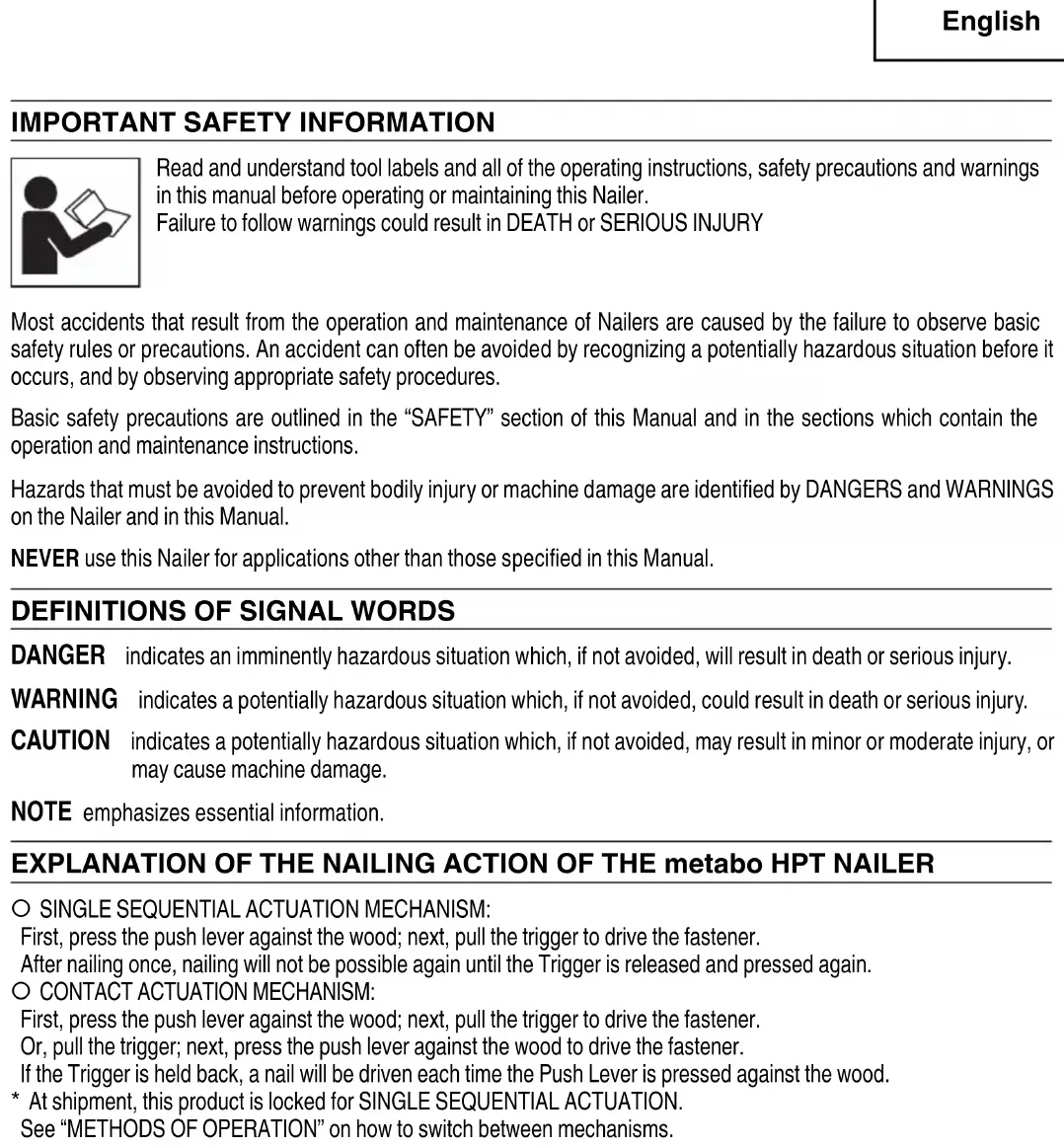
EXPLANATION OF THE NAILING ACTION OF THE metabo HPT NAILER
○ SINGLE SEQUENTIAL ACTUATION MECHANISM:
First, press the push lever against the wood; next, pull the trigger to drive the fastener. After nailing once, nailing will not be possible again until the Trigger is released and pressed again.
O CONTACT ACTUATION MECHANISM:
First, press the push lever against the wood; next, pull the trigger to drive the fastener. Or, pull the trigger; next, press the push lever against the wood to drive the fastener. If the Trigger is held back, a nail will be driven each time the Push Lever is pressed against the wood.
* At shipment, this product is locked for SINGLE SEQUENTIAL ACTUATION. See "METHODS OF OPERATION" on how to switch between mechanisms.
SAFETY
IMPORTANT SAFETY INSTRUCTIONS - FOR USING NAILERS
INSTRUCTIONS PERTAINING TO A RISK OF FIRE, ELECTRIC SHOCK, OR INJURY TO PERSONS
- General
To reduce the risks of electric shock, fire, and injury to persons, READ ALL THE INSTRUCTIONS BEFORE USING THE TOOL.
DANGER
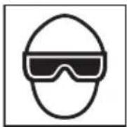
1. OPERATORS AND OTHERS IN WORK AREA MUST WEAR EYE PROTECTION (SAFETY GLASSES WITH SIDE SHIELDS).

When operating the Nailer, always wear safety glasses with side shields, and make sure others in worst safety glasses, too.
Safety glasses must conform to the requirements of American National Standards Institute, ANSI Z87.1 and provide protection against fl ying particles both from the front and side.
Ordinary eyeglasses do not provide adequate protection.
The employer must enforce the use of safety glasses by the Nailer operator and others in work area.
2. NEVER USE REACTIVE GASES OR OTHER BOTTLED GASES. EXPLOSION MAY OCCUR.
Never use reactive gases such as oxygen, combustible gases or any other bottled gases as a power source for the eNaller.
Use of the above gases is dangerous, as the Nailer will explode.
Use only clean, dry, regulated compressed air.
WARNING
3. NEVER POINT TOOL AT YOURSELF OR OTHERS IN WORK AREA.
Always assume that the Nailer contains fasteners.
Never point the Nailer toward yourself or others, whether it contains fasteners or not.
If fasteners are mistakenly driven, it can lead to severe injuries.
Never engage in horseplay with the Nailer.
Respect the Nailer as a working implement.
4. DO NOT PLACE FINGER ON TRIGGER AND KEEP FINGERS AWAY FROM TRIGGER WHEN NOT DRIVING FASTENERS TO AVOID ACCIDENTAL DISCHARGE.
Never carry the Nailer with finger on Trigger since you could drive a fastener unintentionally and injure yourself or someone else.
Always carry the Nailer by the handle only.
5. KNOW AND UNDERSTAND WHAT TRIGGER SYSTEM YOU ARE USING.
Read and understand section titled "METHODS OF OPERATION." (pages 19 – 21)
6. DO NOT MAKE CONTACT WITH SAFETY TIP (PUSH LEVER) WHEN NOT DRIVING FASTENERS.
SAFETY — Continued
WARNING
When using tools, basic precautions should always be followed, Including the following:
1. Work area
(1) Keep the work area clean and well lighted.
Cluttered benches and dark areas increase the risks of electric shock, fire, and injury to persons.
(2) Do not operate the Nailer in explosive atmospheres, such as in the presence of fl ammable liquids, gases, or combustible dust.
The Nailer is able to create sparks resulting ignition of the dust or fumes.
(3) Keep bystanders, children, and visitors away while operating the Nailer. Distractions are able to result in the loss of control of the Nailer.
2. Personal safety
(1) Stay alert. Focus on your work and use common sense when working with the Nailer. Do not use the Nailer while tired, after having consumed drugs or alcohol, or while under the influence of medication.
A moment of inattention while operating the Nailer increases the risk of injury to persons.
(2) Dress properly. Do not wear loose clothing or jewelry. Contain long hair. Keep hair, clothing, and gloves away from moving parts.
Loose clothes, jewelry, or long hair increases the risk of injury to persons as a result of being caught in moving parts.
(3) Avoid unintentional starting. Be sure the switch is off before connecting to the air supply. Do not carry the Nailer with your finger on the switch or connect the Nailer to the air supply with the switch on.
(4) WARNING – Disconnect the Nailer from the air source before making adjustments, doing Nailer maintenance, clearing jams, touching the Push Lever, attaching or removing the nose cap, when not in use, leaving work area, leaving the Nailer outside of the operator's supervision or control, loading, or unloading the Nailer, handing it to another person, elevating, lowering or otherwise moving the Nailer to a new location. Never attempt to clear a jam or repair the Nailer unless you have disconnected air hose from the Nailer and removed all remaining fasteners from the Nailer. The Nailer should never be left unattended since people who are not familiar with the Nailer might handle it and injure the themselves.
Such precautionary measures reduce the risk of injury to persons.
(5) Do not overreach. Keep proper footing and balance at all times. Proper footing and balance enables better control of the Nailer in unexpected situations.
(6) Use safety equipment. A dust mask, non-skid ng isafelyeshoes and a hard hat must be used for the applicable conditions.
(7) ⚠️ WARNING – Risk of hearing loss. Wear hearing protection.
Hearing protection shall have a Noise Reduction Rating (NRR) determined in accord Environmental Protection Agency rules that is appropriate for noise exposure.
(8) Always wear head protection.
Always wear head protection to protect your head from fl ying objects.
(9) Do not attach the hose or Nailer to your body.
Attach the hose to the structure to reduce the risk of loss of balance if the hose shifts.
(10) WARNING – Drive Nails into proper work surface only. Do not drive nail into other nails. This is able to cause the fastener to be deflected and hit someone, or cause the Nailer to react and result in a risk of injury to persons.
3. Nailer use and care
(1) Use clamps or another practical way to secure and support the workpiece to a stable platform.
Holding the work by hand or against the body is unstable and is able to lead to loss of control.
(2) Do not force the Nailer. Use the correct Nailer for the application. The correct Nailer will do the job better and safer at the rate for which the Nailer is designed.
(3) Do not use the Nailer if the switch does not turn the Nailer on or off. Any Nailer that cannot be controlled with the switch is dangerous and must be repaired.
Never use Nailer which is defective or operating abnormally. If the Nailer appears to be operating unusually, making strange noises, or otherwise appears defective, stop using it immediately and arrange for repairs by a metabo HPT authorized service center.
SAFETY — Continued
WARNING
(4) Disconnect the Nailer from the air source before making any adjustments, changing accessories, or storing the Nailer. Such preventive safety measures reduce the risk of starting the Nailer unintentionally.
(5) Store the Nailer when it is idle out of reach of children and other untrained persons. A Nailer is dangerous in the hands of untrained users.
(6) Maintain the Nailer with care. Keep the Nailer Clean and lubricated for better and safer performance.
(7) Check for misalignment or binding of moving parts, breakage of parts, and any other condition that may affect the Nailer's operation.
If damaged, have the Nailer serviced before Because of high air pressure in the Nailer, cracks in the surface are dangerous. To avoid this, do not drop the Nailer or strike the Nailer against hard surfaces; and do not scratch or engrave signs on the Nailer. Many accidents are caused by poorly maintained Nailers. There is a risk of bursting if the Nailer is damaged.
(8) Do not use the Nailer that is not in proper working order. Tags and physical segregation shall be used for control.
(9) Use only accessories that are identified by metabo HPT for the specific Nailer. Use of an accessory not intended for use with the specific Nailer, increases the risk of injury to persons.
(10) Use only those fasteners listed in the Accessories section of this manual. Fasteners not identified for use with this Nailer by metabo HPT are able to result in a risk of injury to persons of damage when used in this Nailer.
4. Service
(1) Tool service must be performed only by qualified repair personnel.
(2) When servicing a Nailer, use only identical replacement parts. Use only authorized parts.
(3) Use only the lubricants supplied with the Nailer or specified by metabo HPT.
5. Air source
(1) Never connect to an air source that is capable of exceeding 200 psi (13.7 bar 14 kgf/cm ^2 ) if a regulator fails.
Over pressurizing the Nailer is able to result in bursting, abnormal operation, breakage of the Nailer or serious injury to persons.
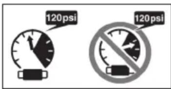
DO NOT EXCEED 120 psi (8.3 bar 8.5 kgf/cm ^4 ).
using only clean, dry, regulated compressed air at the rated pressure or within the rated pressure range as marked on the Nailer.
Always verify prior to using the Nailer that the air source has been adjusted to the rated air pressure or within the rated air-pressure range.
(2) Never use reactive gases such as oxygen, carbon dioxide, combustible gases or any bottled gas as an air source for the Nailer. Such gases are capable of explosion and serious injury to persons.
6. Others
(1) Before starting work, check the nailing operation switching device.
This metabo HPT nailer includes a nailing operation switching device.
Before starting work, check the setting of the operation switching device.
If the switching device is not set properly, the Nailer will not operate correctly.
(2) Always select the switching device that is appropriate to the application and the training of the operator.
(3) When switching between SINGLE SEQUENTIAL and CONTACT, disconnect the air hose and remove all nails.
(4) When the hook is attached, operate only with SINGLE SEQUENTIAL ACTUATION MECHANISM and not with CONTACT ACTUATION MECHANISM.
SAFETY — Continued
WARNING
(5) Be careful of double fi re and being hit by the Nailer due to spring back ("recoil"). After d a nail, the Nailer may recoil causing it to move away from the work surface.
To reduce risk of injury always manage recoil by:
1) always maintaining control of the Nailer.
2) allowing recoil to move the Nailer away from work surface.
3) not resisting recoil such that the Nailer will be forced back into the work surface. In "CONTACT ACTUATION MECHANISM", if push lever is allowed to re-contact work surface before the trigger is released, an unintended discharge of a nail will occur. In order to avoid this undesirable double fire,
○ Intermittent operation (Trigger fire)
① Set the switching device to SINGLE SEQUENTIAL ACTUATION MECHANISM.
② Pull the trigger rapidly and firmly.
○ Continuous operation (Push lever fire)
① Set the switching device to CONTACT ACTUATION MECHANISM.
② Do not press the Nailer against the wood with excessive force.
③ Separate the Nailer from the wood as it recoils after nailing.
4) keeping face and body parts away from the Nailer.
(6) Never Use NON relieving coupler on Nailer. If a non relieving coupler is used on the Nailer, the Nailer can remain charged with air after disconnecting and thus will be able to drive a fastener even after disconnecting. The Nailer and air hose must have a hose coupling such that all pressure is removed from the Nailer when the coupling joint is disconnected.
(7) Check Push Lever before use. Make sure the Push Lever operates properly, and is not inoperable, disconnected, or altered. (The Push Lever may be called "Safety".) Never use the Nailer unless the Push Lever is operating properly, otherwise the Nailer could drive a fastener unexpectedly. Do not tamper with or remove the Push Lever, or otherwise cause the Push Lever to become inoperable.
(8) Keep all screws and covers tightly in place. Keep all screws and covers tightly mounted.
Check their condition periodically. Never use the Nailer if parts are missing or damaged.
(9) Do not load fasteners with Trigger or Push Levering depressed. When loading fasteners into the Nailer or when connecting the air hose,
1) do not depress the Trigger;
2) do not depress the Push Lever; and
3) keep the Nailer pointed downward.
(10) Keep hands and body away from firing head during use. Never place your hands or feet closer than 8 inches (200 mm) from the firing head. A ACT serious injury can result if the fasteners are deflected by the workpiece, or are driven away from the point of entry.
(11) When working close to an edge of a workpiece or at steep angles, or driving fasteners into thin workpiece use care to minimize chipping, splitting or splintering, or free flight, ricochet or piercing of fasteners, which may cause injury.
(12) Never drive fasteners from both sides of a wall at the same time. The fasteners can be driven into and through the wall and hit a person on the opposite side.
(13) Use extra caution when driving the Nailer into existing walls or other blind areas to prevent contact with hidden objects or persons on other side (eg., wires, pipes).
(14) Check for live wires. Avoid the risk of severe electrical shock by checking for live electrical wires that may be hidden by walls, floors or ceilings. Turn off the breaker switch to ensure there are no live wires.
(15) Do not lift, pull or lower the Nailer by the hose.
(16) Do not disconnect air hose from Nailer with finger on Trigger. The Nailer can fire when re-connected to An air supply.
(17) Handle Nailer correctly. Operate the Nailer according to this Manual. Never allow the Nailer to be operated by children, individuals unfamiliar with its operation or unauthorized personnel.
(18) Never use Nailer for applications other than those specified in this manual.
(19) Never modify or alter a Nailer. Doing so may cause it to malfunction and personal injuries may result.
(20) Disconnect the air hose when affixing the hook.
(21) Do not affix the hook on high or unstable locations. Also, do not affix it to the body, clothing, belt or other personal items.
SAFETY — Continued
RESPONSIBILITIES OF EMPLOYER, TOOL OWNER AND TOOL OPERATOR
- Ensure that this MANUAL is available to operators and personnel performing maintenance.
- Select an appropriate switching device considering the applications for which the Nailer is used.
- Train the operator in the safe use of the Nailer as described in this MANUAL.
- Ensure that only persons who have read and understand this MANUAL operate the Nailer.
-
Ensure that Nailers are used only when operators and others in work area are wearing EYE PROTECTION, and other appropriate personal protective equipment such as HEAD, HEARING, FOOT PROTECTION.
-
Enforce the use of EYE PROTECTION by operators and others in work area.
- Ensure that Nailers are kept in safe working order as described in this MANUAL.
- Maintain Nailers properly.
- Ensure that only qualified personnel Nailers.
- Ensure that Nailers that require repair are removed from service and that tags and physical segregation are used as a means of control.
SAVE THIS MANUAL AND KEEP IT AVAILABLE FOR OTHERS!
OPERATION
NOTE: The information contained in this Manual is designed to assist you in the safe operation of the Nailer.
Some illustrations in this Manual may show details or attachments that differ from those on your own Nailer.
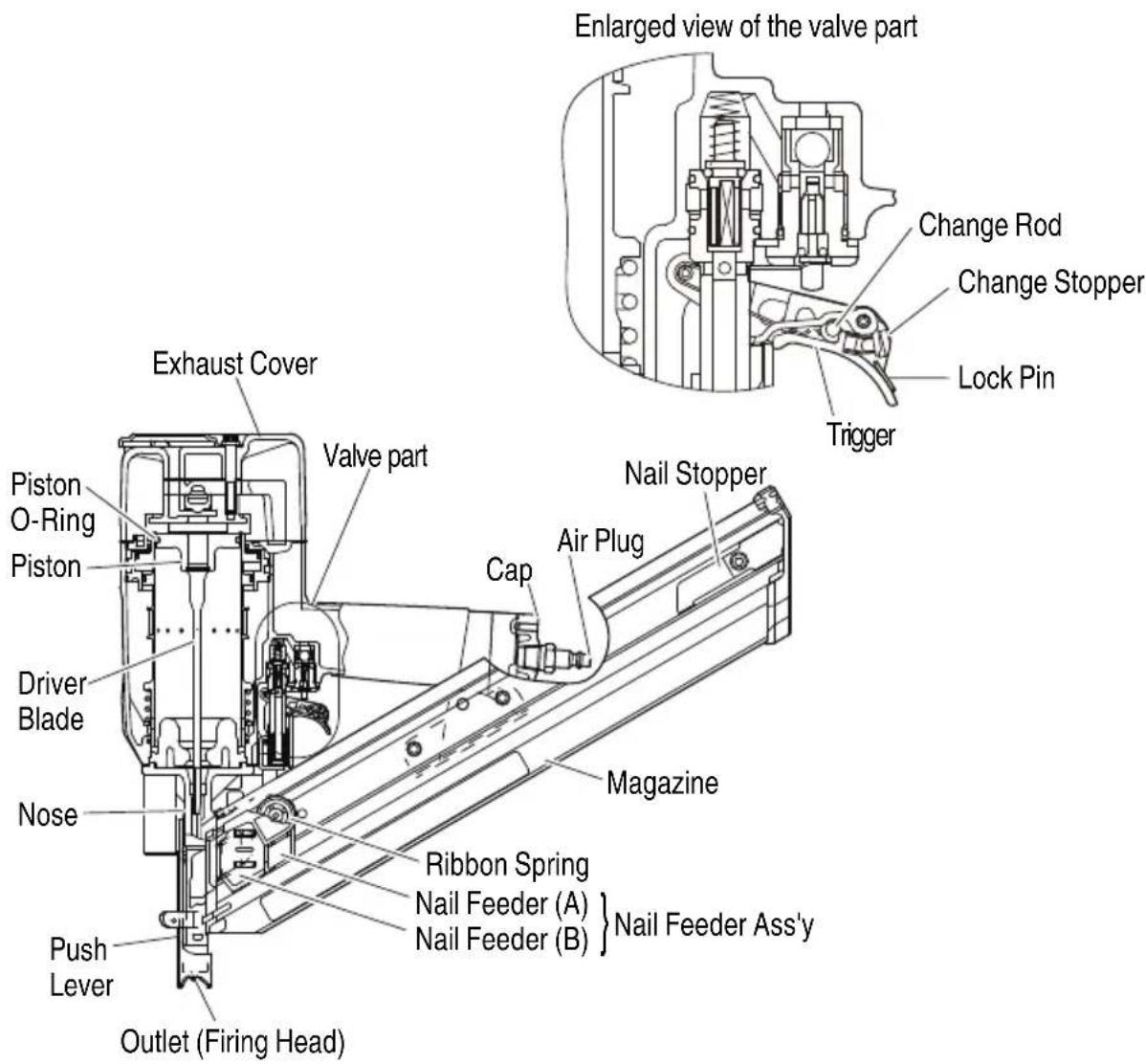
NAME OF PARTS
| Nailing operation switching device | |
 |  |
| SINGLE SEQUENTIAL ACTUATION MECHANISM CONTACT ACTUATION MECHANISM | |
| ● When the lock pin is attached, the tool is fixed to SINGLE SEQUENTIAL ACTUATION.● To operate in CONTACT ACTUATION, the lock pin should be removed by following the steps in “How to Remove the Lock Pin” provided in the “METHODS OF OPERATION”. | |
![[NR83A5] Enlarged view of the valve part Change Rod Change Stopper Lock Pin Trigger Exhaust Cover Valve part Body Cap Air Plug Ribbon Spring Piston O-Ring Piston Driver Blade Nose Adjuster [NR83A5] Push Lever Outlet (Firing Head) Magazine Assembly Stop Lever Nail Feeder [NR83A5(S)] Nose Push Lever Outlet (Firing Head)](/content/2026/04/645273/images/d435dd256cd9737026d2a4c3bdb4b4f7a4f72b501018e7aada78b8038f44601c.jpg)
[NR83AA5]
SPECIFICATIONS
| Model NR83A5 / NR83A5 | (S) NR83AA5 | |
| Operating pressure 70 – 1 | 20 psi (4.9 – 8.3 bar 5 – 8.5 kgf/cm | 2) |
| DimensionsLength × Height × Width | 21-3/16" × 13-3/8" × 4-1/4"(538 mm × 340 mm × 108 mm) | 18-1/8" × 14-3/16" × 4-1/4"(460 mm × 360 mm × 108 mm) |
| Weight 8.8 lbs (4.0 kg) (Without Hook) | 9.0 lbs (4.1 kg) (Without Hook) | |
| Nail capacity 50 – 70 nails | (2 strips) 68 – 94 nails (2 strips) | |
| Air consumption | .088 ft3/cycle at 100 psi(2.5 ltr/cycle at 6.9 bar)(2.5 ltr/cycle at 7 kgf/cm2) | |
| Air inlet 3/8 NPT Thread | ||
NAIL SELECTION

WARNING
- Be sure to use only the genuine metabo HPT nails for the NR83A5 / NR83A5 (S) / NR83AA5. The use of any other nails can result in tool malfunction and/or nail breakdown, leading to serious injuries.
Only nails shown in the Table below can be driven with this Nailer.
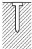
Plastic-collated strip nailsFull-head nails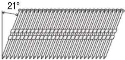 | Min. Max. | |
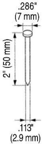 | 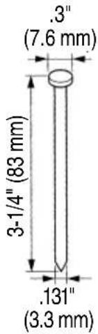 |
Paper collated strip nailsClipped-head nails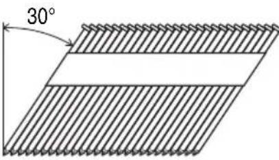 | Min. Max. | .266"(6.8 mm)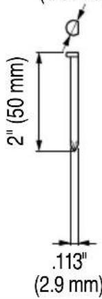 | .280"(7.1 mm)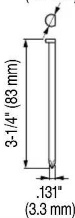 |
ACCESSORIES

WARNING
● Accessories other than those shown below can lead to malfunction and resulting injuries.
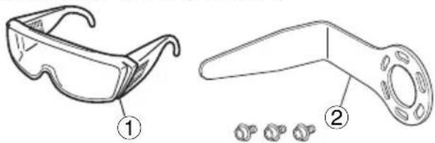
STANDARD ACCESSORIES
natural_image
Technical line drawings of two types of eyewear accessories, one with a numbered label (1) and the other with a numbered label (2), showing different angles and features.① Eye protection .... 1
② Hook....1
OPTIONAL ACCESSORIES
... sold separately
○ Nose cap (Code No. 884080) (except NR83AA5)
○ Pneumatic Tool Lubricant
1.0 oz. (30 cc) oil feeder
(Code No. 877153)
4 oz. (120 cc) oil feeder
(Code No. 874042)
1 quart (1 ltr) can
(Code No. 876212)
NOTE: Accessories are subject to change without any obligation on the part of metabo HPT.
APPLICATIONS
○ Floor and wall framing.
○ Truss build-up, Window build-up.
○ Subfl ooring and roof decking.
○ Wall sheathing.
○ Mobile home and modular housing construction.
BEFORE OPERATION
Read section titled "SAFETY" (pages 4 – 8).
Make sure of the followings before operation.
WORKING ENVIRONMENT

WARNING
● No flammable gas, liquid or other flammable objects at worksite.
● Clear the area of children or unauthorized personnel.
AIR SUPPLY

DANGER
● NEVER use reactive gases or other bottled gases. Explosion may occur.

WARNING
● Never connect Nailer to pressure which potentially exceeds 200 psi (13.7 bar 14 kgf/cm ^2 ) if a regulator fails.
● Never use non relieving coupler on Nailer.
- Power source
○ Use only clean, dry, regulated compressed air as a power source for this Nailer.
Air compressors used to supply compressed air to this Nailer must comply with the requirements of the latest version of ANSI Standard B 19.3 "Safety Standard For Compressors For Process Industries."
○ Moisture or oil in the air compressor may accelerate wear and corrosion in the Nailer.
Drain daily.
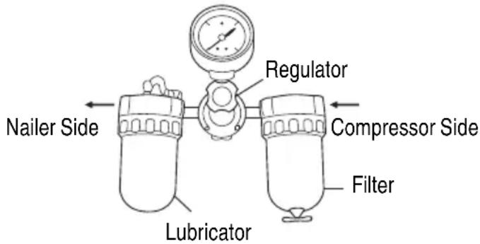
- Filter-Regulator-Lubricator
○ Use a regulator with a pressure range of 0 – 120 psi (0 – 8.3 bar 0 – 8.5 kgf/cm ^2 ).
○ Filter-regulator-lubricator units supply an optimum condition for the Nailer and extend the Nailer life.
These units should always be used.
Filter ....The filter removes moisture and dirt mixed in compressed air.
Drain daily unless fitted with an automatic drain.
Keep the filter clean by regular maintenance.
Regulator.....The regulator controls the operating pressure for safe operation of the Nailer. Inspect the regulator before operation to be sure it operates properly.
Lubricator .... The lubricator supplies an oil mist to the Nailer.
Inspect the lubricator before operation to be sure the supply of adequate.
Use metabo HPT pneumatic tool lubricant.
3. Air hose
Compressed air supply hoses shall have a minimum working pressure rating equal to or greater than the pressure from the power source if a regulator fails, or 150 psi (10.4 bar 10.6 kgf/cm ^2 ), whichever is greater.
4. Air consumption
Using the Air consumption table and the Air compressor size formula, find a correct compressor size.
Air consumption table
| Operating pressure | psi(bar)(kgf/cm2) | 80(5.5)(5.6) | 90(6.2)(6.3) | 100(6.9)(7) |
| Air consumption | ft3/cycle(ltr/cycle) | .062(1.7) | .075(2.1) | .088(2.5) |
Air compressor size formula
Amount of air required
=number of Nailers
× average nails driven each minute per Nailer
× air consumption at given air pressure
× safety factor (always 1.2)
Example: 2 Nailers operating at 100 psi driving 30 nails per minute
Amount of air required
= 2 × 30 × .088(2.5) × 1.2
=6.3 CFM (ft ^3 /min) (180 ltr/min)
After making the calculations as shown above, you should find a compressor providing 6.3 CFM of air that is required.
LUBRICATION
It is important that the Nailer be properly lubricated.
Without proper lubrication, the Nailer will not work I properly and parts will wear prematurely.
○ Use metabo HPT pneumatic tool lubricant.
Do not use detergent oil or additives. These lubricants will harm the O-rings and other rubber parts. This will cause the Nailer to malfunction.
○ Filter-regulator-lubricator units should always be used.
Keep the lubricator filled with metabo HPT pneumatic tool lubricant.
☐ If a lubricator is not available, supply 5 – 10 drops of metabo HPT pneumatic tool lubricant into the air plug on the Nailer twice a day.
COLD WEATHER CARE
- Do not store the Nailer in a cold weather environment. Keep the Nailer in a warm area until beginning the work.
○ If the Nailer is already cold, bring it in a warm area and allow the Nailer to warm up before use.
① Reduce the air pressure to 64 psi (4.4 bar 4.5 kgf/cm2).
② Remove all nails from the Nailer.
③ Connect the air hose and free-fire (blank-fire) the Nailer.
The lowered air pressure will be enough to free-fire the Nailer.
Slow speed operation tends to warm up the moving part.
CAUTION
- Do not free-fire the Nailer at high pressure.
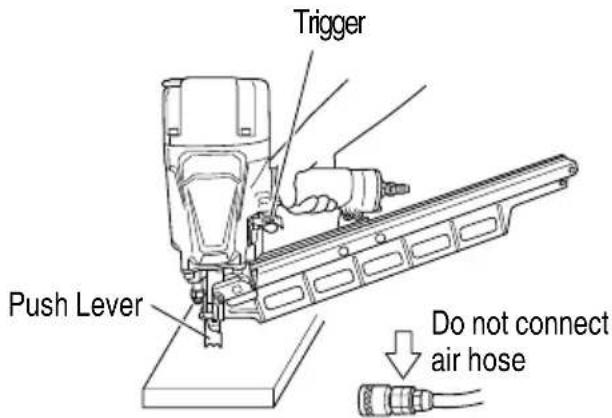
TESTING THE NAILER
DANGER

- Operators and others in work area MUST wear safety glasses with side shields which conforms to ANSI Z87.1 specifications.
Ordinary eyeglasses do not provide adequate protection.

WARNING
● Never use Nailer unless push lever is operating properly.
Before actually beginning the nailing work, test the Nailer by using the checklist below. Conduct the tests in the following order.
If abnormal operation occurs, stop using the Nailer and contact a metabo HPT authorized service center immediately.
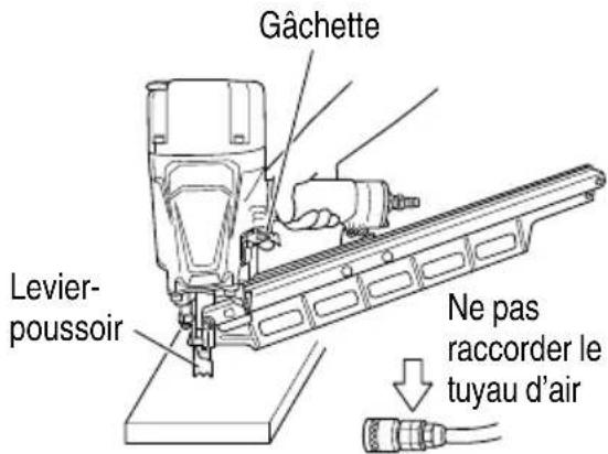
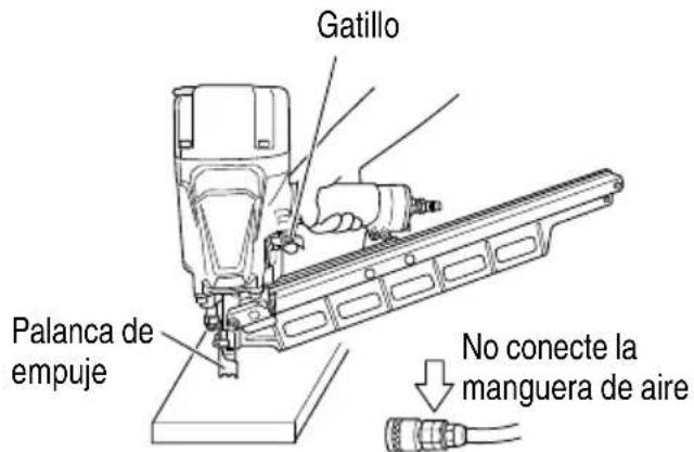
(1) DISCONNECT AIR HOSE FROM NAILER. REMOVE ALL NAILS FROM NAILER.
☐ ALL SCREWS MUST BE TIGHTENED. If any screws are loose, tighten them.
natural_image
Line drawing of a hand inserting a plug into a battery (no text or symbols)☐ THE PUSH LEVER AND TRIGGER MUST MOVE SMOOTHLY.
(2) REMOVE ALL NAILS FROM NAILER.
DO NOT push or rest Push Lever against any surface. DO NOT FORCE OR USE TOOLS TO OPERATE SWITCH. Select SINGLE SEQUENTIAL ACTUATION MODE according to the following steps.
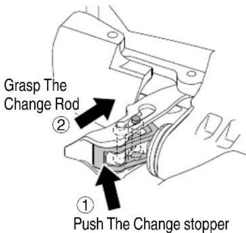
① Open the change stopper by pushing the bottom of trigger.
② Grasp the change rod between two fingers (one on each side of the trigger) and slide it down (Single Sequential Actuation Mode.)
③ Confi rm that the change stopper has completely returned to original position inside the trigger.
(SINGLE SEQUENTIAL ACTUATION MECHANISM).
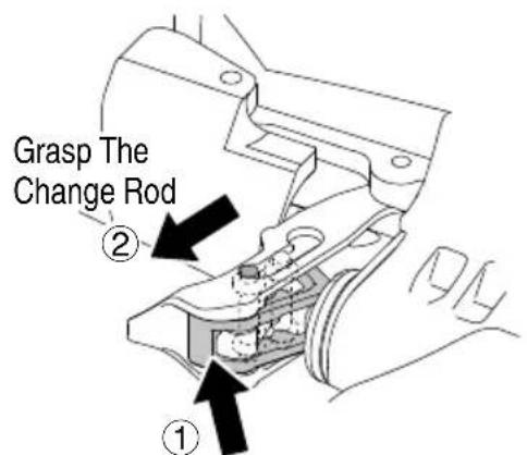
Push The Change stopper
(3) Adjust the air pressure to 70 psi (4.9 bar 5 kgf/cm ^2 ). Connect the air hose.
☐ THE NAILER MUST NOT LEAK AIR.
(4) Remove the finger from the trigger and press the push lever against the wood.
(5) Separate the push lever from the wood.
Next, point the nailer downward, pull the trigger and then wait in that position for 5 seconds or longer.
(6) First pull the Trigger.
Next, depress the Push Lever against the wood.
(7) Without touching the Trigger, depress the Push Lever against the wood.
Next, pull the Trigger.
If the lock pin is left, skip (8) through (10) and proceed from (11).
→ If the lock pin is attached, the unit can be operated in SINGLE SEQUENTIAL ACTUATION MECHANISM.
(8) Disconnect the air hose.
REMOVE ALL NAILS FROM NAILER.
Remove the hook if it is attached.
→ When the hook is attached, do not operate with CONTACT ACTUATION MECHANISM.
DO NOT push or rest Push Lever against any surface.
DO NOT FORCE OR USE ANY TOOLS TO OPERATE SWITCH.
Select CONTACT ACTUATION MODE according to the following steps.
① Open the change stopper by pushing the bottom of trigger.
② Grasp the change rod between two fingers (one on each side of the trigger) and slide it up Actuation Mode.)
③ Confirm that the change stopper has completely returned to original position inside the trigger.
(CONTACT ACTUATION MECHANISM).
(9) Adjust air pressure to 70 psi (4.9 bar 5 kgf/cm ^2 ). Connect the air hose.
☐ THE NAILER MUST NOT LEAK AIR.
(10) With the Nailer off the wood, pull the Trigger. Next, depress the Push Lever against the wood.
(11) Next, depress the Push Lever against the workpiece. Now pull the Trigger.
(12) If no abnormal operation is observed, you may load nails in the Nailer.
Drive nails into the workpiece that is the same type to be used in the actual application.
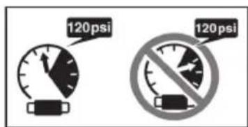
● Do not exceed 120 psi (8.3 bar 8.5 kgf/cm²).
Adjust the air pressure at recommended operating pressure 70 - 120 psi (4.9 - 8.3 bar 5 - 8.5 kgf/cm ^2 ) according to the length of nails and the hardness of workpiece.
The correct air pressure is the lowest pressure which will do the job. Using the Nailer at a higher than required air pressure unnecessarily over stresses the Nailer.
LOADING NAILS

WARNING
● When loading nails into Nailer,
1) do not pull trigger;
2) do not depress push lever; and
3) keep Nailer pointed downward.
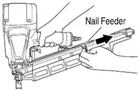
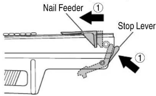
(1) Pull the nail feeder back until it latches
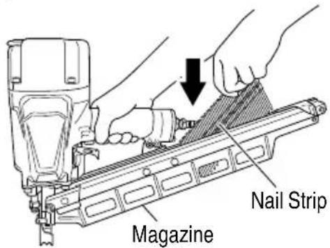
(2) Insert nail strips one by one from above the magazine. Two strips can be loaded at one time.
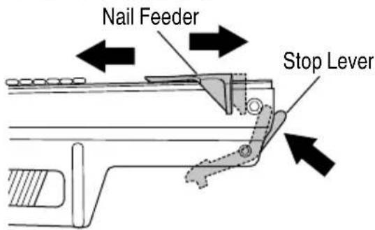
(3) Press the stop lever and slide the nail feeder forward until it contacts the nail strip.
NOTE:
- Quietly push the Nail Feeder against the nail. If the Nail Feeder is released from b magazine and bumped against the nail, the connecting plastic of the nail can be damaged.
● Use nail strip at least 5 nails remaining.
natural_image
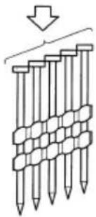
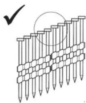
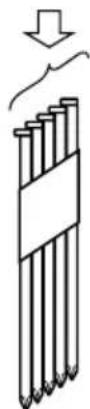
Diagram of stacked pencil-like structures with a downward arrow indicating compression or disassembly (no text or symbols)- Set heads of nails overlapped as shown in the below figure.
natural_image
Diagram of a grid of nail samples with a checkmark and circle highlighting a specific area (no text or symbols present)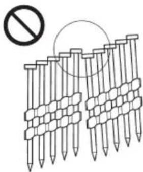
natural_image
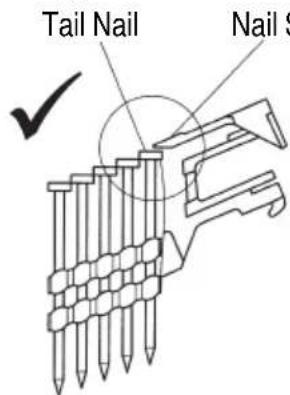
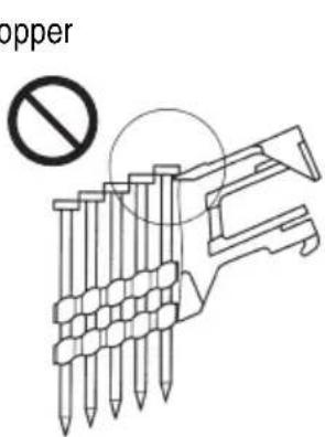
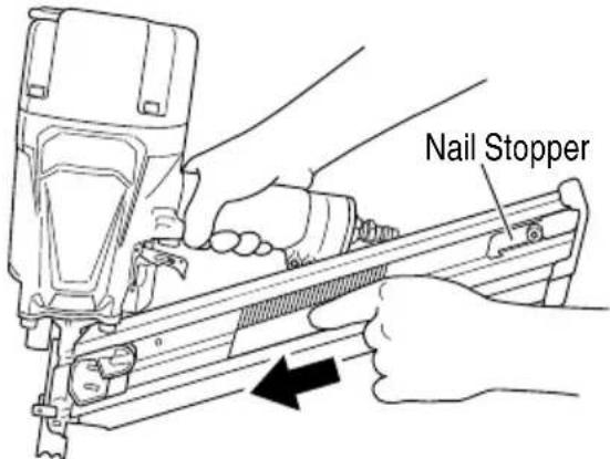
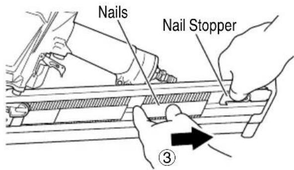
Diagram of nail pad arrangement with a prohibition symbol (no text or labels)● Ensure that the head of tail nail is set under the nail stopper of nail feeder.
The Nailer is now ready to operate.
Removing the nails:

WARNING
● Disconnect air hose from Nailer when removing nails from the magazine.
① Press the stop lever and slide the nail feeder forward quietly.
② Pull out nails from the top of the magazine.

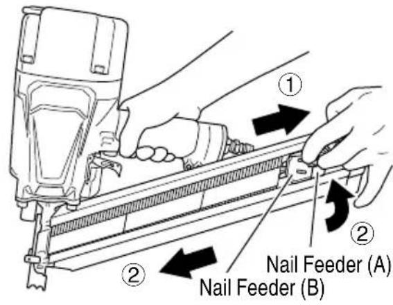
(1) Insert nail strip into rear of magazine.
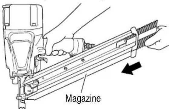
(2) Slide the nail strip forward in the magazine.
The nail strip should pass the nail stopper.
(3) Pull the nail feeder (B) back to engage the nail feeder (A) to the nail strip.
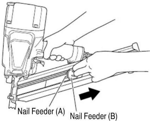
NOTE:
- Quietly push the Nail Feeders (A) and (B) against the nail.
If the Nail Feeders (A) and (B) are released from backward the magazine and bumped against the nail, the connecting paper of the nail can be damaged.
● Use nail strip of more than 5 nails.
The Nailer is now ready to operate.
Removing the nails:

WARNING
- Disconnect air hose from Nailer when removing nails from the magazine.
① Pull the nail feeder (B) backward.
② Return the nail feeder (B) forward quietly while pushing the nail feeder (A).
③ Push the nail stopper toward the magazine side, and pull out nails from the back of the magazine.
NAILER OPERATION
Read section titled "SAFETY" (pages 4 – 8).

DANGER
- Operators and others in work area MUST wear safety glasses with side shields which conforms to ANSI Z87.1 specifications. Ordinary eyeglass e provide adequate protection.

WARNING

- Only person who h and understand this MANUAL should operate the Nailer. - NEVER point tool at yourself or others in work area.
- Keep fi ngers AWAY from trigger when not driving nails to avoid accidental discharge.
● Know and understand what trigger system you are using.
Please read and understand "Methods of Operation" below.
- Inspect the Nailer before operating to determine actuation system. Before starting work, check the nailing operation switching device. This metabo HPT nailer includes a nailing operation switching device. Before starting work, makes switching device is properly set.
If the switching device is not set properly, the nailer will not operate correctly.
● Never place your hands or body closer than 8 inches (200 mm) from fi ring head when using.
● Do not drive nails into other nails; nails can ricochet and hurt someone.
- Do not actuate Nailer unless Nailer is placed firmly against the workpiece.
- When working close to an edge of a workpiece or at steep angles, or driving fasteners into thin workpiece use care to minimize chipping, splitting or splintering, or free fl ight, ricochet or piercing of fasteners, which may cause injury.
● Never drive nails from both sides of a wall at the same time. Nails can be driven into and through the wall and hit a person on the opposite side.
● Never use Nailer which is defective or operating abnormally.
● Do not use Nailer as hammer.
● Disconnect air hose from Nailer when:
1) it is not in use;
2) leaving work area;
3) elevating, lowering or otherwise moving it to another location;
4) handing it to another person;
5) When removing the lock pin.
6) changing switching device;
7) performing any maintenance or repairs;
8) clearing a jam;
9) Nailer is outside of the operator's e a d supervision or control;
10) removing nails from the magazine;
11) adjusting nailing depth; and
12) attaching or removing the nose cap.
13) When installing or removing the hook
14) When affixing the hook
This metabo HPT nailer is equipped with a nailer operation switching device.
Use SINGLE SEQUENTIAL ACTUATION MECHANISM or CONTACT ACTUATION MECHANISM in accordance with the work to be performed.
Explanation of the various nailing operations
○ SINGLE SEQUENTIAL ACTUATION MECHANISM: First, press the push lever against the wood; next, pull the trigger to drive the nail.
After nailing once, nailing will not be possible again until the trigger is released and pressed again.
○ CONTACT ACTUATION MECHANISM: First, press the push lever against the wood; next, pull the trigger to drive the nail. Or,
pull the trigger; next, press the push lever against the wood to drive the nail.
If the trigger is held back, a nail will be driven each time the push lever is pressed against the wood.
METHODS OF OPERATION
This Nailer is equipped with the push lever and does not operate unless the push lever is depressed (upward position).
There are two methods of operation to drive nails with this Nailer.
They are:
- Intermittent operation (Trigger fire):
- Continuous operation (Push lever fire):
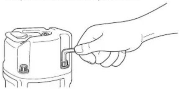
How to Remove the Lock Pin
- When shipped, the tool's drive mode to S I N G L E S E MECHANISM with the lock pin.
- By removing the lock pin as shown below, the tool can be switched between SINGLE SEQUENTIAL ACTUATION and CONTACT ACTUATION.

WARNING
- When removing the lock pin, disconnect the air hose from the tool and remove all nails.
- Please be warned that the once the lock pin is removed, the SINGLE SEQUENTIAL ACTUATION and CONTACT ACTUATION switch function will be activated.
- Use a pair of pliers like the one shown below to pull off the lock pin.
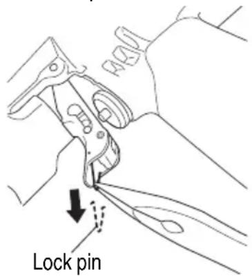

CAUTION
● The lock pin should be discarded after removal.
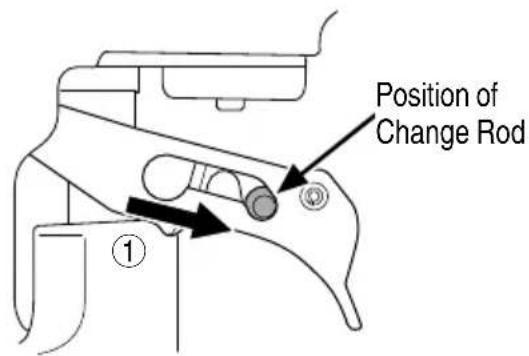
(1) Intermittent operation (Trigger fire)
Use the SINGLE SEQUENTIAL ACTUATION MECHANISM setting.

WARNING
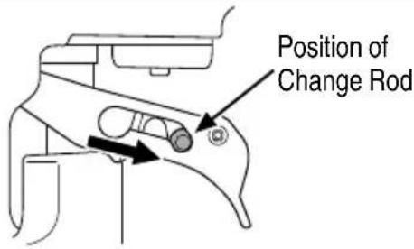
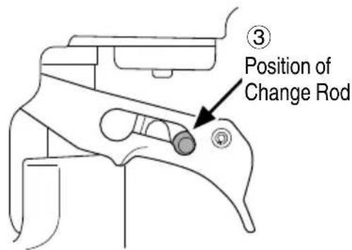
- For intermittent operation, set the change Rod as shown in the figure below. (i.e. Set to SINGLE SEQUENTIAL ACTUATION MECHANISM.)
● To avoid double firing or accidental firing due to recoil.
1) Set the switching device to SINGLE SEQUENTIAL ACTUATION MECHANISM. 2) Pull the trigger rapidly and firmly.
① Follow the steps below to set up the ASINGLE T SEQUENTIAL ACTUATION MECHANISM (as shown in the diagrams that follow).

WARNING
- Disconnect the air hose and remove all nails.
- Do not depress the push lever.
- Do not apply any unnecessary pressure or use any tools to move the switch.
- Do not press the change stopper for any other purpose other than to switch between SINGLE SEQUENTIAL ACTUATION and CONTACT ACTUATION.
1) If the lock pin is left, skip 2) through 3) and proceed from 4).
2) Press the bottom of the trigger and open the change stopper.
3) Grasp the change rod between two fingers and slide it downwards.
(Sets the SINGLE SEQUENTIAL ACTUATION MECHANISM)
4) Make sure that the change rod is in its proper position as shown in the diagram.
(If not, the tool may be set in the CONTACT ACTUATION MECHANISM.)
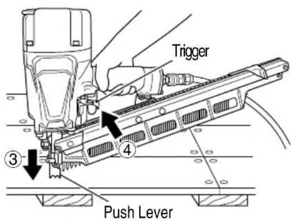
② Position the nail outlet on the workpiece with finger off the trigger.
③ Depress the push lever firmly until it is completely depressed.
④ Pull the trigger to drive a nail.
⑤ Remove finger from the trigger.
To continue nailing in a separate location, move the nailer along the wood, repeating steps ② – ⑤ as required.

WARNING
● A nail will fi re each time the trigger is depressed as long as the push lever remains depressed.
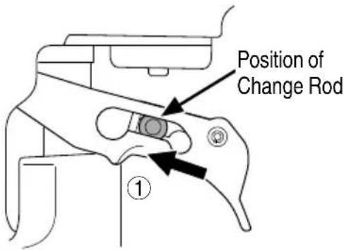
(2) Continuous operation (Push lever fi re) Using CONTACT ACTUATION MECHANISM

WARNING
● To avoid double firing or accidental firing due to recoil.
1) Do not press the nailer against the wood with excessive force.
2) Separate the nailer from the wood as it recoils after nailing.
- If the hook is affixed, do not operate with CONTACT ACTUATION MECHANISM.
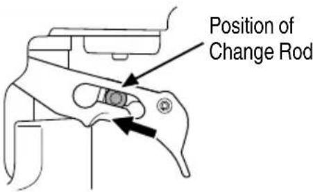
① Follow the steps below to set up the CONTACT ACTUATION MECHANISM (as shown in the diagrams that follow).

WARNING
● Disconnect the air hose and remove all nails.
● Do not depress the push lever.
- Do not apply any unnecessary pressure or use any tools to move the switch.
- Do not press the change stopper for any other purpose other than to switch between SINGLE SEQUENTIAL ACTUATION and CONTACT ACTUATION.
1) Remove the lock pin if it is still attached.
See "How to Remove the Lock Pin" "METHODS OF OPERATION".
2) Press the bottom of the trigger and open the change stopper.
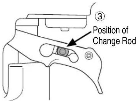
3) Grip the change rod between two fingers and slide it upwards.
(Sets the CONTACT ACTUATION MECHANISM)
4) Make sure that the change rod is in its proper position in the trigger as shown in the diagram. (If not, the tool may not operate properly.)
② Pull the trigger with the Nailer off the workpiece.
③ Depress the push lever against the workpiece to drive a nail.
④ Move the Nailer along the workpiece with a bouncing motion.
Each depression of the push lever will drive a nail.
As soon as the desired number of nails have been driven, remove finger from the trigger.

WARNING
- Keep your finger off the trigger except during fastening operation, because serious injury could result if the push lever accidentally contacts you or others in work area.
- Keep hands and body away from the discharge area. This metabo HPT nailer may bounce from the recoil of driving a fastener and unwanted subsequent fastener may be driven, possibly causing injury.
● Some types of loaded nails can spark out of the muzzle during a nail driving operation. Exercise caution!
The SINGLE SEQUENTIAL ACTUATION MECHANISM is for use where precision fastener placement is desired.
The SINGLE SEQUENTIAL ACTUATION MECHANISM may reduce the possibility of bodily injury to you or others in the work area compared to the CONTACT ACTUATION MECHANISM. This is because it is less likely to drive an unwanted nail if you keep the trigger pulled and accidentally bump the push lever against yourself or others.
The SINGLE SEQUENTIAL ACTUATION MECHANISM may also reduce the speed of operation compared to the CONTACT ACTUATION MECHANISM. The SINGLE SEQUENTIAL ACTUATION MECHANISM is recommended to inexperienced users.
NOTE:
- If all warnings and instructions are followed, safe operation is possible with two systems: SINGLE SEQUENTIAL ACTUATION MECHANISM and CONTACT ACTUATION MECHANISM.
● Always handle nails and package carefully. If nails are dropped, collating plastic may be broken.
● After nailing:
1) disconnect air hose from the Nailer;
2) remove all nails from the Nailer;
3) supply 5 - 10 drops of metabo HPT pneumatic tool lubricant into the air plug on the Nailer; and
4) open the petcock on the air compressor tank to drain any moisture.
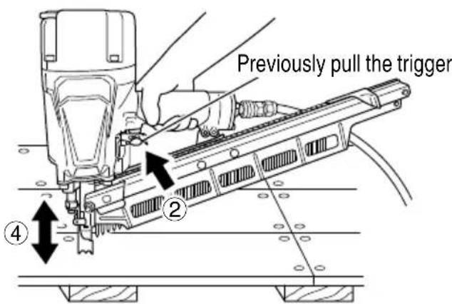
ADJUSTING THE NAILING DEPTH [Only NR83A5 (with depth adjustment)]
![METABO NR83AA5 - ADJUSTING THE NAILING DEPTH [Only NR83A5 (with depth adjustment)] - 1](/content/2026/04/645273/images/669b9f0ddb91f0c34bc7c94ef5a9540d367a0fc34ee592e8dc6ada39ec8ec797.jpg)
WARNING
- Disconnect the air hose from the nailer before turning the adjuster.
To assure that each nail penetrates to the same depth, be sure that:
1) the air pressure to the Nailer remains constant (regulator is installed and working properly), and
2) the Nailer is always held firmly against the workpiece. If nails are driven too deep or shallow into the workpiece, adjust the nailing in the following order.
① DISCONNECT AIR HOSE FROM NAILER
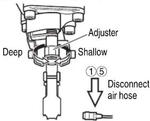
② If nails are driven too deep, turn the adjuster to the shallow side. Adjustments are in half-turn increments.
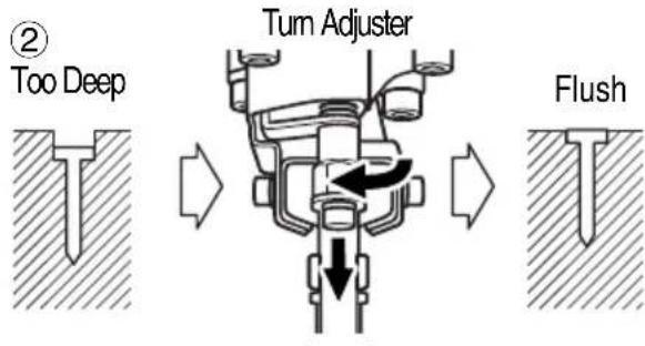
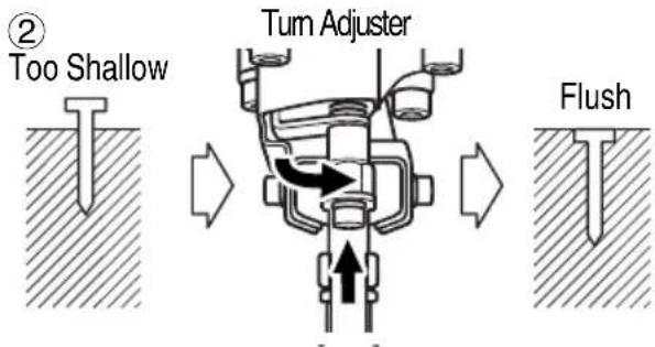
If nails are driven too shallow, turn the adjuster to the deep side.
③ Stop turning the adjuster when a suitable position is reached for a nailing test.
④ Connect the air hose.
ALWAYS WEAR EYE PROTECTION.
Perform a nailing test.
⑤ DISCONNECT AIR HOSE FROM NAILER.
⑥ Choose a suitable position for the adjuster.
RAFTER HOOK
With the NR83A5, NR83A5 (S) and NR83AA5, an included hook can be attached by using three M5 × 16 fl ange bolts which are included with the tools. When the tool is detached from the hose and not in use, the hook can be used to store the unit.

WARNING
- When attaching or detaching the hook, make sure the hose is detached and the nails are removed from the tool.
(1) How to attach the hook
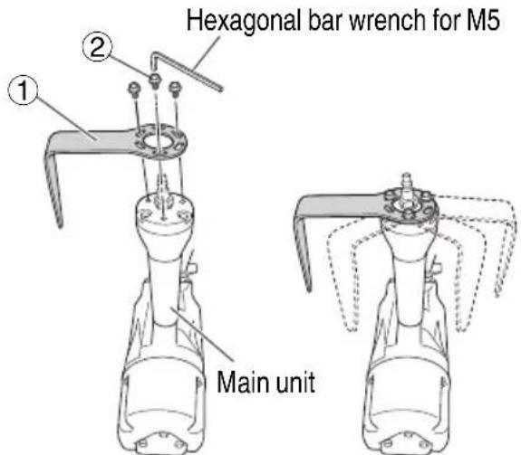
Fig. 1 Fig. 2
- When attaching, use a hexagonal bar wrench for M5 (separate).
- Fix the hook (①) to the main unit in three locations using the M5 × 16 fl ange bolts (②) (Fig. 1).
| Fastening Torque | |
| 8.3±0.5 N·m 6.1 ±0.4 ft.lbs 85±5 kgf | ·cm |
- The hook can be attached in any direction. Adjust the hook according to the operating environment (Fig. 2).
(2) How to detach the hook Detach the hook by reversing the aforementioned steps for attaching the hook.

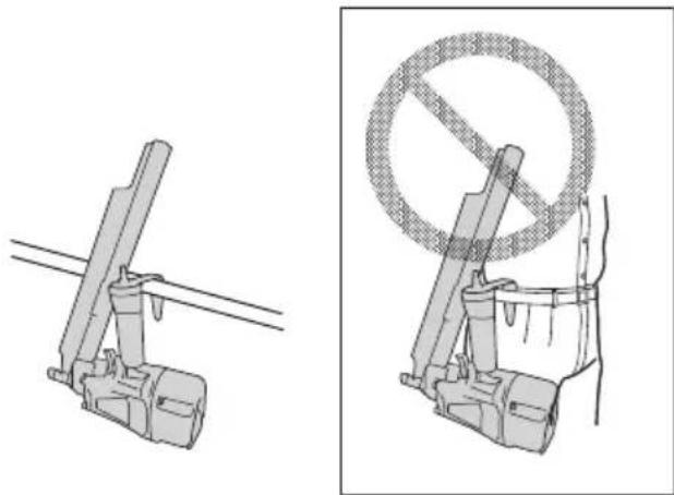
WARNING
- When the hook is attached, operate only with SINGLE SEQUENTIAL ACTUATION MECHANISM and not with CONTACT ACTUATION MECHANISM. For switching between SINGLE SEQUENTIAL and CONTACT, see the appropriate section in "METHODS OF OPERATION". - Disconnect the air hose when hook the unit. - Do not hook on high or unstable locations. Also, do not hook it to the body, clothing, belt or other personal items.
natural_image
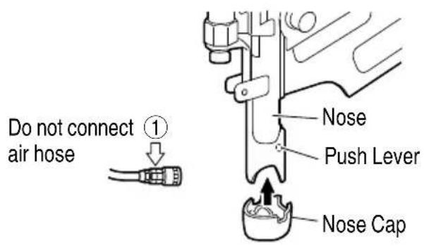
Two technical diagrams showing mechanical components and a circular no-smoking symbol (no text or labels present)USING THE NOSE CAP (except NR83AA5)

WARNING
● Disconnect the air hose from the nailer before attaching or removing the nose cap.
If you like to protect the surface of workpiece against scratches or markings made by the push lever, attach the accessory nose cap to the push lever.
① DISCONNECT AIR HOSE FROM NAILER.
② Put the nose cap to the toe of the push lever.
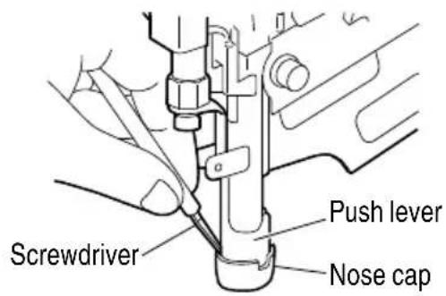
NOTE:
● The nose cap may reduce nailing depth due to its thickness. Re-adjustment of nailing depth is required.
Nose cap can be removed from the push lever using a screwdriver or thin rod.
MAINTENANCE
NOTE: The information contained in this Manual is designed to assist you in the safe maintenance of the Nailer.
Some illustrations in this Manual may show details or attachments that differ from those on your own Nailer.
MAINTENANCE AND INSPECTION
Read section titled "SAFETY" (pages 4 – 8).

WARNING
- Disconnect air hose and remove all nails from Nailer when:
1) doing maintenance and inspection; and
2) clearing a jam.
- Clearing a jam
Remove a jammed nail in the following order:
① DISCONNECT AIR HOSE.
② Insert a rod into the outlet.
Tap the rod with a hammer.
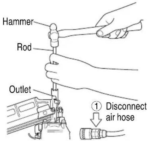
③ Remove the jammed nail with a slotted screw driver.
④ In case of frequent jam, contact a metab authorized service center.
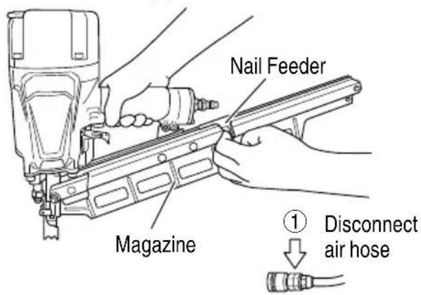
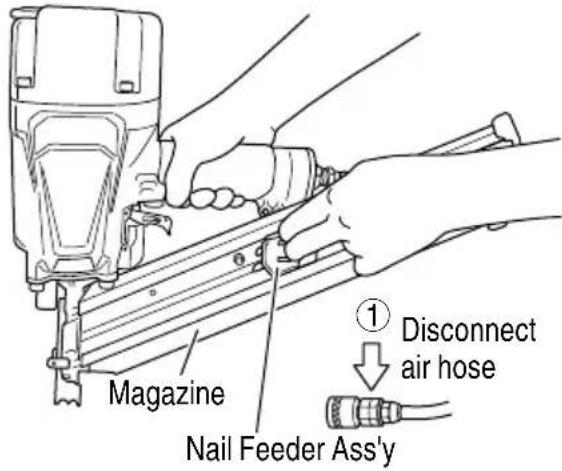
- Inspecting the magazine
① DISCONNECT AIR HOSE.
② Clean the magazine. Remove plastic tips or wooden tips which may have accumulated in the magazine. Lubricate it with metabo HPT pneumatic tool lubricant.
- Storing
When not in use for an extended period, apply a thin coat of the lubricant to the steel parts to avoid rust.
○ Do not store the Nailer in a cold weather environment.
Keep the Nailer in a warm area.
When not in use, the Nailer should be stored in a warm and dry place.
Keep out of reach children.
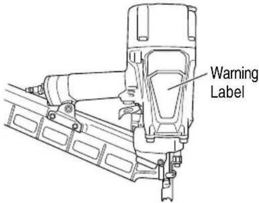
- WARNING LABEL
Do not use the Nailer with missing or damaged WARNING LABEL.
A new WARNING LABEL is available from a metabo HPT authorized service center.
- Maintenance chart (See page 25)
-
Operator troubleshooting (See page 25)
-
Service parts list
CAUTION
● Repair, modification and inspection of metabo HPT Power Tools must be carried out by a metabo HPT Authorized Service Center. This Parts List will be helpful if presented with the tool to the metabo HPT Authorized Service Center when requesting repair or other maintenance. In the operation and maintenance of power tools, the safety regulations and standards prescribed in each country must be observed.
MODIFICATIONS:
Metabo HPT Power Tools are constantly being improved and modified to incorporate the latest technological advancements.
Accordingly, some parts may be changed without prior notice.
SERVICE AND REPAIRS
WARNING
● Only service personnel trained by metabo HPT, distributor or employer shall repair the Nailer.
● Use only parts supplied or recommended by metabo HPT for repair.
All quality Nailers will eventually require servicing or replacement of parts because of wear from normal use.
NOTE: Specifications are subject to change without any obligation on the part of metabo HPT.
Maintenance chart
| ACTION WHY HOW | ||
| Drain air line fi Iter daily. Prevent accumulation of moisture and dirt. | Open manual petcock. | |
| Keep lubricator filled. | Keep the Nailer lubricated. | Fill with metabo HPT pneumatic tool lubricant. |
| Clean fi Iter element and blow air through fi Iter in direction opposite to normal flow daily. | Prevent clogging of filter with dirt. | Follow manufacturer's instructions. |
| Clean magazine and feeder mechanism. | Prevent a jam. Blow clean daily. | |
| Keep push lever working properly. | Promote operator safety and efficient Nailer operation. | Blow clean daily. |
| Lubricate the Nailer after nailing. Extend the Nailer life. Supply 5 – 10 drops of lubricant into the Nailer. | ||
| Drain air compressor daily. | Keep the Nailer operated properly. | Open petcock on air compressor tank. |
Operator troubleshooting
Most minor problems can be resolved quickly and easily using the table below.
If problems persist, contact a metabo HPT authorized service center for assistance.
| PROBLEM | CHECK METHOD | CORRECTION |
| Nailer operates, but no nail is driven. | Check for a jam. | Clear a jam. |
| Check function of nail feeder per page 23. | Clean and lubricate. | |
| Ribbon spring weakened or damaged? | Replace ribbon spring | |
| Check for proper nails. | Use only recommended nails. | |
| Weak drive.Slow to cycle. | Check air pressure. | Increase air pressure. (Do not exceed 120 psi (8.3 bar 8.5 kgf/cm2).) |
| —— | Use metabo HPT pneumatic tool lubricant. | |
| Driver blade worn? | Contact metabo HPT for replacement. | |
| Piston O-ring worn or damaged? | ||
| Drives too deep. | Check air pressure. | Reduce air pressure.(Adjust 70 – 120 psi) |
| Skipping nails. Intermittent feed. | Check for proper nails. | Use only recommended nails. |
| Check function of nail feeder per page 23. | Clean and lubricate. | |
| Ribbon spring weakened or damaged? | Replace ribbon spring. | |
| —— | Use metabo HPT pneumatic tool lubricant. | |
| Piston O-ring cut or heavily worn? | Contact metabo HPT for replacement. | |
| Nails jam.Driven nail is bent. | Check for proper nails. | Use only recommended nails. |
| Driver blade worn? | Contact metabo HPT for replacement. | |
| Drives properly during normal operation, but does not drive fully at faster nailing speeds. | Check inside diameter of air hose. Use | larger air hose. |
INFORMATION IMPORTANTE DE SÉCURITÉ

natural_image
Technical line drawing of two types of eyeglasses with numbered labels (1 and 2), no text or symbols present.① Lunettes de protection ....1
② Crochet ....1
ACCESSOIRES EN OPTION
natural_image
Line drawing of a hand inserting a plug into a battery (no text or symbols)□ LE LEVIER-POUSSOIR ET LA GACHETTE DOIVENT FONCTIONNER AVEC SOUPLESSE.
natural_image
Line drawing of a hairpin tool in operation, showing a hand operating the component (no text or symbols present)natural_image
Diagram of stacked pencil-like structures with a downward arrow indicating compression or disassembly (no text or symbols)natural_image
Line drawing of a mechanical device with lever and base (no text or symbols)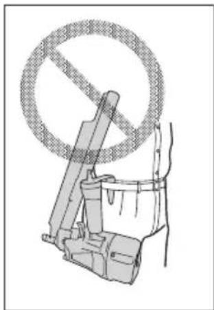
natural_image
Illustration of a bucket with a diagonal no-smoking symbol above it, no text or symbols present.UTILISATION DU CAPUCHON DE BEC (sauf NR83AA5)
⚠ AVERTISSEMENT
natural_image
Technical line drawing of two types of eyewear accessories with numbered labels (1 and 2), no text or symbols present.natural_image
Line drawing of a hand inserting a small lock into a battery (no text or symbols)□ LA PALANCA DE EMPUJE DEBERÁ PODER ACCIONARSE SIN DIFICULTAD.
natural_image
Diagram of stacked pencil-like structures with a downward arrow indicating compression or disassembly (no text or symbols)natural_image
Mechanical assembly diagram showing directional arrows and internal components (no text or labels)A ras
natural_image
Technical line drawings of two mechanical device configurations, one with a lever mechanism and the other showing a circular ring and bucket (no text or symbols)| Item No. | Part Name Q'TY | |
| 1 | HEX. SOCKET HD. BOLT (W/FLANGE) M6×45 | 3 |
| 2 | T O P C O V E R 1 | |
| 3 | HEX. SOCKET HD. BOLT (W/SP.WASHER) M6×25 | 4 |
| 4 | E X H A U S T C O | V |
| 5 | G A S K E T ( B ) | 1 |
| 6 | G A S K E T ( F ) | 1 |
| 7 | E X H A U S T P I | E |
| 8 | G A S K E T ( C ) | 1 |
| 9 | E X H A U S T V A | L |
| 10 HEAD CAP AND GASKET SET 1 | ||
| 11 O-RING (1AP- 48) | 1 | |
| 12 | PISTON | 1 |
| 13 | O-RING | 3 |
| 14 CYLINDER O-RING (I.D 63.1) | 1 | |
| 15 | CYLINDER PLATE | 1 |
| 16 CYLINDER O-RING (I.D 79.3) | 1 | |
| 17 | CYLINDER | 1 |
| 18 CYLINDER O-RING (I.D 69.3) | 1 | |
| 19 | CYLINDER RING | 1 |
| 20 CYLINDER SPRING | 1 | |
| 21 BASE WASHER | 1 | |
| 22 CYLINDER GUIDE | 1 | |
| 23 LABEL | 1 | |
| 24 O-RING (I.D 1.8) 1 | ||
| 25 WARNING LABEL | 1 | |
| 26 BODY ASS'Y | 1 | |
| 27 CYLINDER O-RING (I.D 63.9) | 1 | |
| 28 PISTON BUMPER (B) 1 | ||
| 29 GASKET (A) | 1 | |
| 30 NYLOCK BOLT (W/FLANGE) M6 ×12 | 1 | |
| 31 GUARD | 1 | |
| 32 NYLOCK HEX. SOCKET HD. BOLT M8 ×22 | 4 | |
| 33 NOSE | 1 | |
| 34 NOSE RUBBER | 1 | |
| 35 NYLOCK BOLT (W/FLANGE) M8 ×16 | 1 | |
| 36 NYLON NUT M6 3 | ||
| 37 HANDLE ARM | 1 | |
| 38 GASKET (G) | 1 | |
| 39 GRIP RUBBER | 1 | |
| 40 GASKET (H) | 1 | |
| 41 CAP (B) | 1 | |
| 42 HEX. SOCKET HD. BOLT M5 ×18 | 3 | |
| 43 AIR PLUG NPT 3/8 | 1 | |
| 44 PLUNGER (B) SPRING | 1 | |
| 45 PLUNGER (B) | 1 | |
| 46 PUSHING LEVER (C) | 1 | |
| 47 SPRING | 1 | |
| 48 PUSHING LEVER | 1 | |
| 49 NAME PLATE | 1 | |
| 50 TRIGGER PIN | 1 | |
| 51 VALVE GUARD | 1 | |
| 52 ROLL PIN D3 ×45 | 1 | |
| 53 TRIGGER ARM SPRING | 2 | |
| 54 CHANGE ROD | 1 | |
| 55 TRIGGER | 1 | |
| 56 ROLL PIN D2.5 | 1 | |
| 57 PLUNGER SPRING | 1 | |
| 58 O-RING (P-4) | 1 | |
| 59 PLUNGER (A) | 1 | |
E
;
V
R
E
E
| Item No. | Part Name Q'TY | |
| 60 O-RING (I.D 10.7) | 2 | |
| 61 VALVE BUSHING (A) | 1 | |
| 62 TRIGGER SPRING | 1 | |
| 63 TRIGGER ARM | 1 | |
| 64^1 CHANGE STOPPER | 1 | |
| 65 LOCK PIN | 1 | |
| 66 VALVE PACKING | 1 | |
| 67 URETHANE BALL (C) D7.14 | 1 | |
| 68 O-RING (S-12) | 1 | |
| 69 VALVE PLATE | 1 | |
| 70 TRIGGER VALVE BUSHING | 1 | |
| 71 TRIGGER PLUNGER | 1 | |
| 72 O-RING | 1 | |
| 73 SLEEVE | 1 | |
| 74 MAGAZINE COVER | 1 | |
| 75 NAIL RAIL | 1 | |
| 76 NAIL FEEDER (A) | 1 | |
| 77 ROLL PIN D4 ×40 | 1 | |
| 78 NAIL FEEDER (B) | 1 | |
| 79 FEEDER SPRING | 1 | |
| 80 NAIL FEEDER ASS'Y | 1 | |
| 81 RIBBON SPRING | 1 | |
| 82 NEEDLE ROLLER D4 ×20 | 1 | |
| 83 MAGAZINE | 1 | |
| 84 LABEL (A) | 1 | |
| 85 HEX. SOCKET HD. BOLT (W/FLANGE) M6 ×12 | 3 | |
| 86 NAIL STOPPER | 1 | |
| 501 SAFETY GLASSES | 1 | |
| 502 HOOK ASS'Y | 1 | |
| 503 HOOK | 1 | |
| 504 HEX. SOCKET HD. BOLT (W/FLANGE) M5 ×14 | 3 | |
Issued by
Koki Holdings Co., Ltd.
Shinagawa Intercity Tower A, 15-1, Konan 2-chome, Minato-ku, Tokyo 108-6020, Japan
Distributed by
Koki Holdings America Ltd.
1111 Broadway Ave, Braselton, Georgia, 30517
Koki Holdings America Ltd. Canadian Branch
3405 American Drive, Units 9-10, Mississauga, ON, L4V 1T6


- Instruction and safety manual
- DANGER
- SAFETY
- OPERATION
- MAINTENANCE
- TABLE DES MATIÈRES
- Français
- SECURITE
- UTILISATION
- IMPORTANT SAFETY INFORMATION
- DEFINITIONS OF SIGNAL WORDS
- EXPLANATION OF THE NAILING ACTION OF THE metabo HPT NAILER
- IMPORTANT SAFETY INSTRUCTIONS - FOR USING NAILERS
- - General
- OPERATORS AND OTHERS IN WORK AREA MUST WEAR EYE PROTECTION (SAFETY GLASSES WITH SIDE SHIELDS).
- NEVER USE REACTIVE GASES OR OTHER BOTTLED GASES. EXPLOSION MAY OCCUR.
- WARNING
- NEVER POINT TOOL AT YOURSELF OR OTHERS IN WORK AREA.
- DO NOT PLACE FINGER ON TRIGGER AND KEEP FINGERS AWAY FROM TRIGGER WHEN NOT DRIVING FASTENERS TO AVOID ACCIDENTAL DISCHARGE.
- KNOW AND UNDERSTAND WHAT TRIGGER SYSTEM YOU ARE USING.
- DO NOT MAKE CONTACT WITH SAFETY TIP (PUSH LEVER) WHEN NOT DRIVING FASTENERS.
- SAFETY — Continued
- Work area
- Personal safety
- Nailer use and care
- Service
- Air source
- Others
- RESPONSIBILITIES OF EMPLOYER, TOOL OWNER AND TOOL OPERATOR
- SAVE THIS MANUAL AND KEEP IT AVAILABLE FOR OTHERS!
- NAME OF PARTS
- NAIL SELECTION
- ACCESSORIES
- OPTIONAL ACCESSORIES
- APPLICATIONS
- BEFORE OPERATION
- WORKING ENVIRONMENT
- AIR SUPPLY
- Air hose
- Air consumption
- Air compressor size formula
- LUBRICATION
- COLD WEATHER CARE
- CAUTION
- TESTING THE NAILER
- LOADING NAILS
- NOTE:
- NAILER OPERATION
- METHODS OF OPERATION
- ADJUSTING THE NAILING DEPTH [Only NR83A5 (with depth adjustment)]
- RAFTER HOOK
- USING THE NOSE CAP (except NR83AA5)
- MAINTENANCE AND INSPECTION
- MODIFICATIONS:
- SERVICE AND REPAIRS
- Operator troubleshooting
- INFORMATION IMPORTANTE DE SÉCURITÉ
- ACCESSOIRES EN OPTION
- UTILISATION DU CAPUCHON DE BEC (sauf NR83AA5)
- ⚠ AVERTISSEMENT
- Koki Holdings Co., Ltd.
- Koki Holdings America Ltd.
- Koki Holdings America Ltd. Canadian Branch
Brand : METABO
Model : NR83AA5
Category : Stapler