
PS44008 - Lawn mower Earthwise - Free user manual and instructions
Find the device manual for free PS44008 Earthwise in PDF.

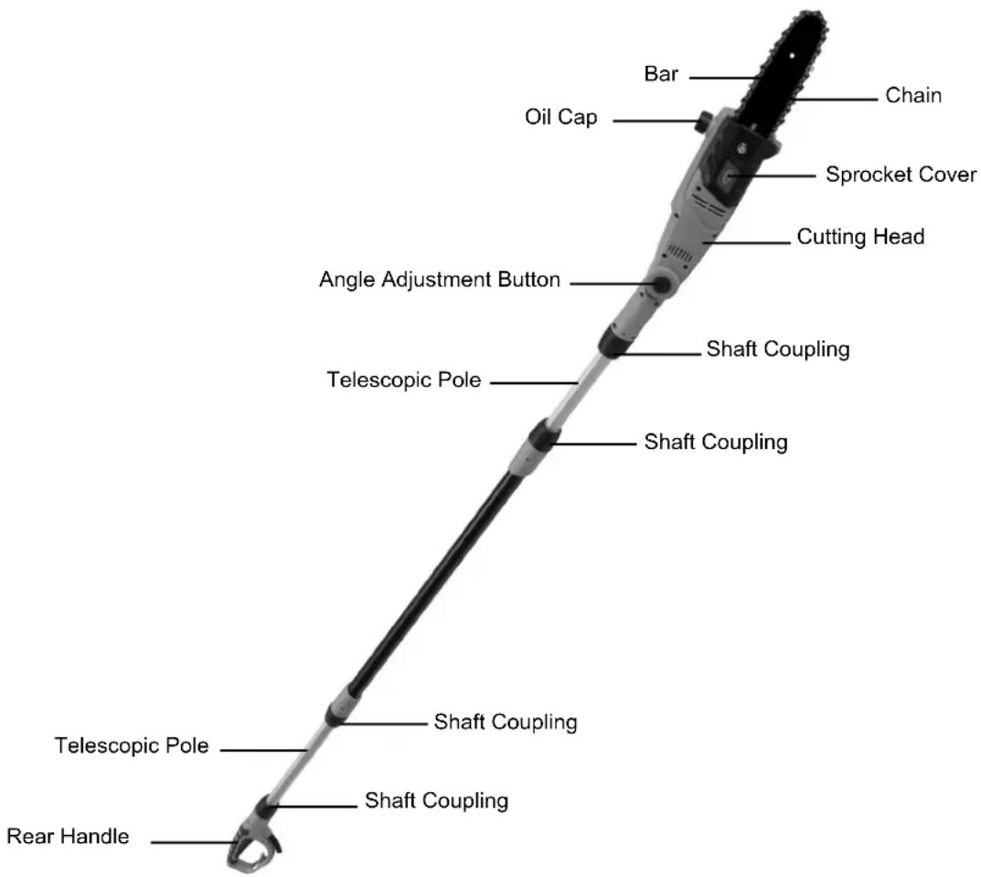
| Product Type | Electric Pole Saw (Pruner) |
| Brand | Earthwise |
| Model | PS44008 |
| Power | 6.5 A, 120 V, 60 Hz, AC only |
| Chain Speed | 11 m/s |
| Guide Bar Length | 20 cm (8 in) |
| Total Extended Length | 2.81 m (9 ft 3 in) |
| Weight | 3.7 kg (8.2 lb) |
| Telescopic Shaft | Yes, adjustable length |
| Adjustable Cutting Head | Yes, tilts from -30° to +30° |
| Lubrication | Automatic, built-in oil reservoir |
| Double Insulation | Yes, no grounding needed |
| Rear Handle | With switch and safety button |
| Maximum Cutting Capacity | Branch diameter up to 15-18 cm (6-7 in) |
| Chain Type | Standard saw chain, replaceable |
| Chain Tension System | Adjust by tension bolt and hex key |
| Drive Sprocket | Lubricatable, replaceable |
| Guide Bar Material | Steel |
| Chain Guard | Protective case included |
| Included Accessories | Hex key, protective case, instruction manual |
| Recommended Use | Pruning and cutting branches |
| Warranty | 2 years limited |
| Customer Service | 1-800-633-1501, www.americanlawnmower.com |
Frequently Asked Questions - PS44008 Earthwise
User questions about PS44008 Earthwise
0 question about this device. Answer the ones you know or ask your own.
Ask a new question about this device
Download the instructions for your Lawn mower in PDF format for free! Find your manual PS44008 - Earthwise and take your electronic device back in hand. On this page are published all the documents necessary for the use of your device. PS44008 by Earthwise.
USER MANUAL PS44008 Earthwise
Copyright. All Rights Reserved.
Model PS44008

natural_image
Close-up of a mechanical tool with long black and gray metal rod, no visible text or symbols

Intertek
5006496
This product has been engineered and manufactured to our high standard for dependability, ease of operation, and operator safety. Properly cared for, it will give you years of rugged, trouble-free performance.

WARNING: To reduce the risk of injury, the user must read and understand the owner's manual before using this product.
Thank you for your purchase.
DO NOT RETURN THIS PRODUCT TO THE STORE. OPERATING, ASSEMBLY, PARTS, SERVICE QUESTIONS? GO TO WWW.AMERICANLAWNMOWER.COM OR CALL 1-800-633-1501 BETWEEN 8:00 AM—5:00 PM EST FOR ASSISTANCE.
GENERAL POWER TOOL SAFETY WARNINGS
WARNING: Read all safety warnings and instructions.
Failure to follow the warnings and instructions may result in electric shock, fire and/or serious injury.
Save all warnings and instructions for future reference.
The term “power tool” in the warnings refers to your mains-operated (corded) power tool or battery-operated (cordless) power tool.
Work area safety
- Keep work area clean and well lit. Cluttered or dark areas invite accidents.
- Do not operate power tools in explosive atmospheres, such as in the presence of flammable liquids, gases or dust. Power tools create sparks which may ignite the dust or fumes.
- Keep children and bystanders away while operating a power tool. Distractions can cause you to lose control.
Electrical safety
- Power tool plugs must match the outlet. Never modify the plug in any way. Do not use any adapter plugs with earthed (grounded) power tools. Unmodified plugs and matching outlets will reduce risk of electric shock.
- Avoid body contact with earthed or grounded surfaces such as pipes, radiators, ranges and refrigerators. There is an increased risk of electric shock if your body is earthed or grounded.
- Do not expose power tools to rain or wet conditions. Water entering a power tool will increase the risk of electric shock.
- Do not abuse the cord. Never use the cord for carrying, pulling or unplugging the power tool. Keep cord away from heat, oil, sharp edges or moving parts. Damaged or entangled cords increase the risk of electric shock.
- When operating a power tool outdoors, use an extension cord suitable for outdoor use. Use of a cord suitable for outdoor use reduces the risk of electric shock.
- If operating a power tool in a damp location is unavoidable, use a ground fault circuit interrupter (GFCI) protected supply. Use of a GFCI reduces the risk of electric shock.
Personal safety
- Stay alert, watch what you are doing and use common sense when operating a power tool. Do not use a power tool while you are tired or under the influence of drugs, alcohol or medication. A moment of inattention while operating power tools may result in serious personal injury.
- Use personal protective equipment. Always wear eye protection. Protective equipment such as dust mask, non-skid safety shoes, hard hat, or hearing protection used for appropriate conditions will reduce personal injuries.
- Prevent unintentional starting. Ensure the switch is in the off-position before connecting to power source and/or battery pack, picking up or carrying the tool. Carrying power tools with your finger on the switch or energising power tools that have the switch on invites accidents.
- Remove any adjusting key or wrench before turning the power tool on. A wrench or a key left attached to a rotating part of the power tool may result in personal injury.
- Do not overreach. Keep proper footing and balance at all times. This enables better control of the power tool in unexpected situations.
- Dress properly. Do not wear loose clothing or jewelry. Keep your hair, clothing and gloves away from moving parts. Loose clothes, jewelry or long hair can be caught in moving parts.
- If devices are provided for the connection of dust extraction and collection facilities, ensure these are connected and properly used. Use of dust collection can reduce dust-related hazards.
Power tool use and care
- Do not force the power tool. Use the correct power tool for your application. The correct power tool will do the job better and safer at the rate for which it was designed.
- Do not use the power tool if the switch does not turn it on and off. Any power tool that cannot be controlled with the switch is dangerous and must be repaired.
- Disconnect the plug from the power source and/or the battery pack from the power tool before making any adjustments, changing accessories, or storing power tools. Such preventive safety measures reduce the risk of starting the power tool accidentally.
- Store idle power tools out of the reach of children and do not allow persons unfamiliar with the power tool or these instructions to operate the power tool. Power tools are dangerous in the hands of untrained users.
- Maintain power tools. Check for misalignment or binding of moving parts, breakage of parts and any other condition that may affect the power tool's operation. If damaged, have the power tool repaired before use. Many accidents are caused by poorly maintained power tools.
- Keep cutting tools sharp and clean. Properly maintained cutting tools with sharp cutting edges are less likely to bind and are easier to control.
GENERAL POWER TOOL SAFETY WARNINGS
- Use the power tool, accessories and tool bits etc. in accordance with these instructions, taking into account the working conditions and the work to be performed. Use of the power tool for operations different from those intended could result in a hazardous situation.
Service
- Have your power tool serviced by a qualified repair
person using only identical replacement parts. This will ensure that the safety of the power tool is maintained.
- When servicing a power tool, use only identical replacement parts. Follow instructions in the Maintenance section of this manual. Use of unauthorized parts or failure to follow Maintenance instructions may create a risk of shock or injury.
POLE SAW SAFETY WARNINGS
- Keep all parts of the body away from the saw chain when the pole saw is operating. Before you start the pole saw, make sure the saw chain is not contacting anything. A moment of inattention while operating pole saws may cause entanglement of your clothing or body with the saw chain.
- Hold the power tool by insulated gripping surfaces only, because the saw chain may contact hidden wiring or its own cord. Saw chains contacting a live wire may make exposed metal parts of the power tool live and could give the operator an electric shock.
- Wear safety glasses and hearing protection. Further protective equipment for head, hands, legs and feet is recommended. Adequate protective clothing will reduce personal injury by flying debris or accidental contact with the saw chain.
- Always keep proper footing and operate the pole saw only when standing on fixed, secure and level surface. Slippery or unstable surfaces may cause a loss of balance or control of the pole saw.
-
When cutting a limb that is under tension be alert for spring back. When the tension in the wood fibres is released the spring loaded limb may strike the operator and/or throw the pole saw out of control.
-
Use extreme caution when cutting brush and saplings. The slender material may catch the saw chain and be whipped toward you or pull you off balance.
- Follow instructions for lubricating, chain tensioning and changing accessories. Improperly tensioned or lubricated chain may either break or increase the chance for kickback.
- Keep handles dry, clean, and free from oil and grease. Greasy, oily handles are slippery causing loss of control.
- Cut wood only. Do not use pole saw for purposes not intended. Use of the pole saw for operations different than intended could result in a hazardous situation.
- Only use replacement bars and chains specified by the manufacturer. Incorrect replacement bars and chains may cause chain breakage and/or kickback.
- Follow the manufacturer's sharpening and maintenance instructions for the saw chain. Decreasing the depth gauge height can lead to increased kickback.
EXTENSION CORD. Make sure your extension cord is in good condition. When using an extension cord, be sure it is heavy enough to carry the current your product will draw. An undersized extension cord will cause a drop in line voltage resulting in loss of power and overheating. The following table shows the correct size to use depending on cord length and nameplate ampere rating. If in doubt, use the next heavier gage. The smaller the gage number, the heavier the cord.
| Minimum Gage for Cord Sets | |||||
| Volts | Total Length of cord in Feet | ||||
| 120V | 0-25 | 26-50 | 51-100 | 101-150 | |
| Ampere Rating | |||||
| More Than | Not More Than | American wire Gage | |||
| 0 | - 6 | 18 | 16 | 16 | 14 |
| 6 | - 10 | 18 | 16 | 14 | 12 |
| 10 | - 12 | 16 | 16 | 14 | 12 |
| 12 | - 16 | 14 | 12 | Not Recommended | |
WARNING: Use out door extension cords marked SW-A, SOW-A, STW-A, SJW-A, or SJTW-A. These cords are rated for outdoor use and reduce the risk of electric shock.
DOUBLE INSULATION—Double Insulation is a concept in safety in electric power tools, which eliminates the need for the usual three-wire grounded power cord. All exposed metal parts are isolated from the internal metal motor components with protecting insulation. Double insulated tools do not need to be grounded.
NOTE: The double insulated system is intended to protect the user from shock resulting from a break in the tool's internal insulation. Observe all normal safety precautions to avoid electrical shock.
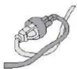
It is possible to tie the extension cord and power cord in a knot to prevent them from becoming disconnected during use. Make the knot as shown, then connect the plug end of the power cord into the receptacle end of the extension cord. This method can also be used to tie two extension cords together.
POLARIZED PLUGS—To reduce the risk of electric shock, this equipment has a polarized plug (one blade is wider than the other). This equipment must be used with a suitable polarized 2 wire or 3 wire extension cord. Polarized connections will fit together only one way. Make sure that the receptacle end of the extension cord has large and small blade slot widths. If the plug does not fit fully into the extension cord, reverse the plug. If it still does not fit obtain a suitable extension cord. If the extension cord does not fit fully into the outlet, contact a qualified electrician to install the proper outlet. Do not change the tool plug or extension cord in any way.
CHECK DAMAGED PARTS – Before further use of the tools, a guard or other part that is damaged should be carefully checked to determine that it will operate properly and perform its intended function. Check for alignment of moving parts, binding of moving parts, breakage of parts, mounting and any other condition that may affect its operation. A guard or other part that is damaged should be properly repaired or replaced. Call our customer service help line at 1-800-633-1501 for assistance.
⚠ WARNING: California Proposition 65: This product contains chemicals known to the State of California to cause cancer, birth defects or other reproductive harm.
WARNING: Some dust and debris created by this tool could contain chemicals known to the State of California to cause cancer, birth defects or other reproductive harm. Some examples of these chemicals are:
- chemicals in fertilizers
- compounds in insecticides, herbicides and pesticides
- arsenic and chromium from chemically treated lumber
Your risk of exposure to these chemicals varies depending on how often you do this type of work. To reduce your exposure, work in a well ventilated area and with approved safety equipment such as dust masks that are specially designed to filter out microscopic particles.
WARNING: Cancer and Reproductive Harm - www.P65Warnings.ca.gov.
CAUTION: Never stand under the limb being trimmed. Position yourself out of the way of falling debris.
PRODUCT SPECIFICATIONS
PS44008
Input.... 120V, 60Hz, 6.5A, AC Only
Speed 11m/s
Bar Length....8 in. Bar
Extended Length....9 ft. 3 in.
Weight 8.2 lbs.
Telescopic Pole - Automatic Bar and Chain Oiling - Adjustable Cutting Head
ASSEMBLY
UNPACKING
This product requires assembly.
Carefully remove the product and any accessories from the box. Make sure that all items listed in the packing list are included.
Inspect the product carefully to make sure no breakage or damage occurred during shipping.
Do not discard the packing material until you have carefully inspected and satisfactorily operated the product.
PACKING LIST
- Cutting Head
- Pole Assembly
- Rear Handle
- Blade Cover
- Hex Key
- Owner's Manual
⚠ WARNING: If any parts are damaged or missing, do not operate this product until the parts are replaced. Failure to heed this warning could result in serious personal injury.
If any parts are damaged or missing, please call customer service at 1-800-633-1501 for assistance.
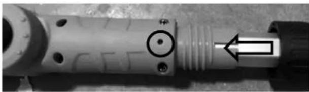
POLE AND CUT HEAD ASSEMBLY
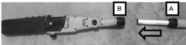
- Loosen the shaft coupling A by turning it counter-clockwise and pull out the extension pole to the desired length. Tighten the shaft coupling A by turning it clockwise.
natural_image
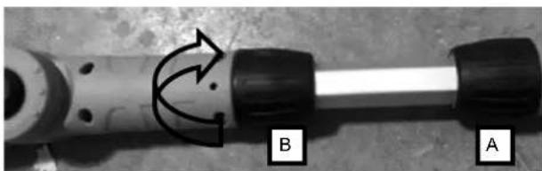
Close-up of a mechanical tool with labeled parts A and B, showing internal components and an arrow indicating direction (no text or symbols beyond labels)- Loosen the shaft coupling B by turning it counter-clockwise.
natural_image
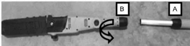
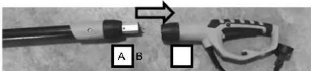
Close-up of a mechanical tool with labeled points A and B, showing a curved arrow indicating motion (no text or symbols beyond labels)- Align the arrow on the cutting head with the protruded lock pin on the shaft.

natural_image
Close-up of two mechanical components with arrows pointing to features (no visible text or symbols)- Insert the pole into the cutting head until the pin locks in place.
natural_image
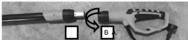
Close-up of a mechanical component with a circular feature and an arrow pointing to a section (no visible text or symbols)- Tighten the shaft coupling B by turning it clockwise.
natural_image
Close-up of a mechanical component with labeled parts A and B, showing rotational motion indicated by arrows (no text or symbols beyond labels)POLE AND HANDLE ASSEMBLY
- Loosen the shaft coupling A by turning it counter-clockwise and pull out the extension pole to the desired length. Tighten the shaft coupling A by turning it clockwise.
natural_image
Close-up of two electrical connectors labeled A and B, showing wiring and components (no text or symbols beyond labels)- Loosen the shaft coupling B by turning it counter-clockwise.
natural_image
Close-up of a mechanical device with labeled components (no readable text or symbols)- Align the arrow on the handle with the protruded lock pin on the shaft.

natural_image
Close-up of a mechanical component with two arrows pointing to features, no visible text or symbols- Insert the pole into the handle until the pin locks in place.

natural_image
Close-up of a mechanical component with a circular feature and an arrow pointing to it (no visible text or symbols)- Tighten the shaft coupling B by turning it clockwise.

DIS-ASSEMBLE POLE AND CUTTING HEAD/HANDLE
To disassemble pole and cutting head or handle,
- Loosen the shaft coupling by turning it counter-clockwise;
- Use a small nail to depress the lock pin in the slot;
- Pull them apart.
ADJUSTING THE LENGTH OF THE TELESCOPIC POLE
- To adjust the telescopic pole, disconnect the product from the power supply. Rotate the shaft coupling counterclockwise to loosen. Extend the pole to the desired length.
NOTE: Only extend the pole to minimum length required to reach the limb or shrub to be cut. - Lock the pole in position by turning the shaft coupling clockwise firmly to secure.
WARNING: Failure to lock the telescopic pole coupling as directed could result in personal injury.

INSTALLING/REPLACING THE GUIDE BAR AND CHAIN
DANGER: Never start the motor before installing the guide bar, chain, chain cover and tension knob. Without all these parts in place, the clutch can fly off or explode, exposing the user to possible serious injury.
WARNING: To avoid serious personal injury, read and understand all the safety instructions provided.
⚠ WARNING: Before performing any maintenance, make sure the tool is unplugged from the power supply. Failure to heed this warning could result in serious personal injury.
CATUION: Always wear gloves when handling the bar and chain; these components are sharp and may contain burrs, which can cause serious injury.
WARNING: Never touch or adjust the chain while the motor is running. The saw chain is very sharp. Always wear protective gloves when performing maintenance to the chain to avoid possible serious lacerations.
NOTE: When replacing the guide bar and chain, use only identical replacement parts.
-
Disconnect pole saw from power supply.
-
Loosen the sprocket cover bolt by turning it counterclockwise with the hex key provided.
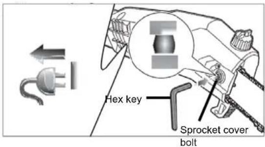
- Remove the sprocket cover.
- Remove the bar and chain from the mounting surface.

- Remove the old chain from the bar.
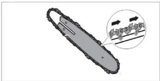
- Lay out the new saw chain in a loop and straighten any kinks. The cutters should face in the direction of the chain rotation. If they face backwards, turn the loop over.

- Place the chain drive links into the bar groove.
NOTE: Make certain of the direction of chain.
- Position the chain so there is a loop at the back of the bar.
natural_image
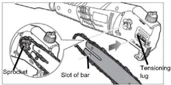
Mechanical chain diagram showing gear and chain components (no text or labels)- Hold the chain in position on the bar and place the loop around the sprocket.
- Fit the bar flush against the mounting surface so that the tensioning lug is in the slot of the bar.
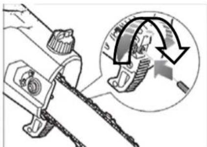
- Replace the sprocket cover.
- Tighten cover bolt, but leave the bar free to move for tension adjustment.
- Remove all slack from the chain by turning the chain tensioning bolt clockwise with the hex key provided until the chain seats snugly against the bar with the drive links in the bar groove.
natural_image
Mechanical assembly diagram showing a chain with a magnified inset highlighting a curved mechanical component (no text or symbols present)- Tighten the sprocket cover bolt with the hex key provided.
TENSIONING THE SAW CHAIN
- Loosen the cover bolt counterclockwise with the hex key provided.
- To tighten the chain, turn the tensioning bolt clockwise. To loosen the tension, turn the tensioning bolt counter-clockwise.
- Tighten the sprocket cover by turning the cover bolt clockwise with the hex key provided.
- Re-adjust tension of the saw chain when necessary.
NOTE: The chain is correctly tensioned when there is no sag on the underside of the guide bar, then chain is snug, but it can be turned by hand without binding.
NOTE: A new chain tends to stretch, check chain tension frequently and tension as required.
OPERATING
Before you start the unit, make sure the pole saw is not contacting any object.
TO TURN THE TOOL ON
Push the safety button in with your thumb and then squeeze the switch trigger with your fingers. Once the tool is running, you can release the safety button.
TO TURN THE TOOL OFF
Release the switch trigger.
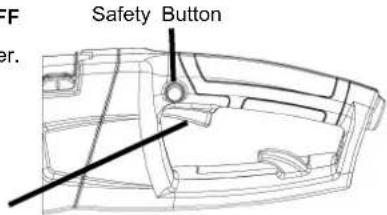
Switch Trigger
WARNING: To guard against injury, observe the following:
- Read owner's manual before using.
- Save owner's manual.
- Keep hands away from blades.
- Keep hands on handles. Don't overreach.
A good, firm grip on the pole and handle with both hands will help you maintain control. Place one hand on the pole and your other hand on the rear handle with your thumbs and fingers encircling the pole and handle. A firm grip together with positioning handle against your body will help you maintain control of the saw. Don't let go.
WARNING: Do not operate pole saw in a tree, on a ladder, or on a scaffold; this is extremely dangerous.
CAUTION: Chain coasts after pole saw is turned off.
Do not use under wet conditions.
Use extreme caution when cutting small size brush, saplings or limbs under tension, because slender and tense material may catch the saw and be whipped toward you, pulling you off balance or springing back.
WARNING: Do not allow familiarity with this type of tool to make you careless. Remember that a careless fraction of a second is sufficient to inflict serious injury.
WARNING: Do not cut trees near electrical wires or buildings.
CAUTION: Failure to lubricate the chain will cause damage to the bar and chain. Use only a good quality bar and chain oil or, if not available, unused SAE 30 weight motor oil may be substituted. One minute of use will consume approx. 0.15 fl. oz. (5ml) of oil.
NOTE: It is normal for oil to seep from the chainsaw cutting head when not in use. To prevent seepage, empty the oil tank after each use. When storing the unit for a long period of time (3 months or longer) be sure the chain is lightly lubricated; this will prevent rust on the chain and bar sprocket.
WARNING: Do Not use the pole saw with any type of accessory or attachment. Such usage might be hazardous.
WARNING: Beware of the cord while operating the saw. Keep the cord away from the chain. Be careful not to trip over the extension cord.
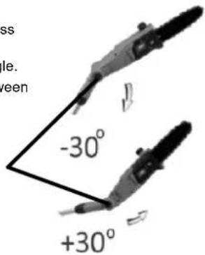
ADJUSTING THE ANGLE OF POLE SAW HEAD
- To adjust the sawing angle, press the angle adjustment button.
- Turn the saw to the desired angle.
- The angle can be adjusted between -30 and 30 degrees.
Angle Adjustment Button
WARNING: Kickback may occur when the moving chain contacts an object at the upper portion of the tip of the guide bar or when the wood closes in and pinches the chain saw in the cut. Contact at the upper portion of the tip of the guide bar can cause the chain to dig into the object and stop the chain for an instant. The result is a lightening fast, reverse reaction which kicks the guide bar up and back toward the operator. If the chain saw is pinched along the top of the guide bar, the guide bar can be driven rapidly back toward the operator. Either of these reactions can cause loss of saw control which can result in serious injury. Do not rely exclusively upon the safety devices built into the saw. As a chain saw user, you should
take several steps to keep your cutting jobs free from accident or injury.
natural_image
Diagram of a chain drive with a gear and directional arrow (no text or labels)The following precautions should be followed to minimize
kickback:
- Always grip the pole and handle firmly with both hands when unit is running. Place one hand on the pole and your other hand on the rear handle with your thumbs and fingers encircling the pole and handle. A firm grip together with positioning handle against your body will help you maintain control of the saw if kickback occurs.
- Make sure that the area in which you are cutting is free from obstructions. Do not let the nose of the guide bar contact a log, branch, fence or any other obstruction that could be hit while you are operating the saw.
- Always cut with the unit running at full speed. Fully squeeze the throttle trigger and maintain a steady cutting speed.
- Wear non-slip gloves for maximum grip protection.
Cut lower branches first to allow the top branches more room to fall.
Work slowly, keeping both hands on the saw with a firm grip.
Maintain secure footing and balance.
WARNING: To protect yourself from electrocution, maintain a min. of 50 ft. (15m) from over head electrical lines.
WARNING: Keep bystanders at least 50 ft. away.
WARNING: Do not cut trees near electrical wires or buildings. If chain jams on any electrical cord or line, DO NOT TOUCH THE BAR AND CHAIN. THEY CAN BECOME ELECTRICALLY LIVE AND VERY DANGEROUS.
OPERATING
PROPER CUTTING STANCE
Weight should be balanced with both feet on solid ground.
Keep left arm with elbow locked in a "straight arm" position to withstand any kickback force when using pole saw. Your right hand should be gripping the handle and positioned firmly against body for added support.
Your body should always be to the left of the chain line.
BASIC CUTTING PROCEDURE
Small trees up to 6-7 inches in diameter are usually cut in a single cut. Large tree limbs require notch cuts. Notch cuts determine the direction the tree will fall.
WARNING: If the tree limb starts to fall in the wrong direction, or if the saw gets caught or hung up during the fall, leave the saw and save yourself.
WARNING: Periodically glance at the top of the tree during the back-cut to assure the tree limb is going to fall in the desired direction.
Practice cutting a few small limbs using the following technique to get the "feel" of using the saw before you begin a major sawing operation.
Take the proper stance in front of the wood with the saw in the "off" position.
Squeeze the trigger and let the chain accelerate to full speed before entering the cut.
Hold the pole saw firmly with both hands.
Keep the unit running the entire time you are cutting, maintain a steady speed.
Allow the chain to cut for you; exert only light downward pressure. If you force the cut, damage to the bar, chain, or unit can result in serious injury.
Do not put pressure on the saw at the end of the cut.
When felling the top of a small tree, keep everyone a safe distance from the cutting area. During felling operations, the safe distance should be at lease twice the height of the largest trees in the felling area. If the tree makes contact with any utility line, the utility company should be notified immediately.
Always cut with both feet on solid ground to prevent being pulled or knocked off balance.
Do not extend arms above shoulder level when operating the pole saws. limb. Make second cut from above limb. Continue cut until you cut limb off.
LIMBING
Limbing is removing branches from a fallen tree.
Work slowly, keeping both hands on the pole saw with a firm grip.
Always make sure your footing is secure and your weight is distributed evenly on both feet.
Leave the larger support limbs under the tree to keep the tree off the ground while cutting.
Limbs should be cut one at a time. Remove the cut limbs from the work area often to help keep the work area clean and safe.
Branches under tension should be cut from the bottom up to avoid binding the pole saw.
Keep the tree between you and the pole saw while limbing. Cut from the side of the tree opposite the branch you are cutting.
WARNING: Never climb into a tree to limb or prune. Do not stand on ladders, platforms, a log, or in any position which can cause you to lose your balance or control of the saw.
LIMBING

CUT LIMBS ONE AT A TIME AND LEAVE SUPPORT
LIMBS UNDER TREE UNTIL LOG IS CUT
PRUNING
Pruning is trimming limbs from a live tree.
Work slowly, keep both hands on the pole saw with a firm grip and the handle positioned firmly against your body for added control and ease of handling. Always make sure your footing is secure and your weight is distributed evenly on both feet.
When pruning trees it is important not to make the finishing cut next to the main limb or trunk until you have cut off the limb further out to reduce the weight. This prevents stripping the bark from the main member.
Make first cut six inches from tree trunk as possible on underside of limb stub. Use top of guide bar to make this cut. Cut 1/3 through diameter of stub.
Move two to four inches farther out on limb. Make second cut from above 12 . Continue cut until you cut limb off.
PRUNING
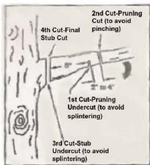
Make third cut as close to tree trunk as possible on underside of limb stub. Use top of guide bar to make this cut. Cut 1/3 through diameter of stub.
Make fourth cut directly above third cut. Cut down to meet third cut. This will remove limb stub.
SPRINGPOLES
A spring pole is branch, or sapling which is bent under tension by other wood so that it springs back if the wood holding it is cut or removed.
WARNING: Watch out for spring poles, they are dangerous. They could result in severe or fatal injury.
CHAIN TENSION AND MAINTENANCE
CHAIN TENSION
Stop the motor before setting the chain tension. Make sure the sprocket cover bolt is loosened to finger tight, turn the chain tensioning bolt clockwise to tension the chain. A cold chain will be correctly tensioned when there is no slack on the underside of the guide bar, the chain is snug, but it can be turned by hand without binding.
Chain must be re-tensioned whenever the flats on the drive links hang out of the bar groove.
During normal saw operation, the temperature of the chain will increase. The drive links of a correctly tensioned warm chain will hang approximately .050 in. (1.25mm) out of the bar groove. Be aware that chain tensioned while warm, may be too tight upon cooling. Check the "cold tension" before next use.
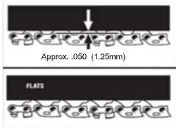
NOTE: A new chain tends to stretch, check chain tension frequently and tension as required.
CHAIN MAINTENANCE
CAUTION: Disconnect the saw from the power supply and make sure the chain has stopped before you do any work on the saw.
For smooth and fast cutting, chain needs to be maintained properly. The chain requires sharpening when the wood chips are small and powdery, the chain must be forced through the wood during cutting, or the chain cuts to one side. During maintenance of your chain remember:
- Improper filing angle of the side plate can increase the risk of severe kickback.
- Raker (depth gauge) clearance.
- Too low increases the potential for kickback.
- Not low enough decreases cutting ability.
- If cutter teeth have hit hard objects such as nails and stones, or have been abraded by mud or sand on the wood, have service dealer sharpen chain.
NOTE: Inspect the drive sprocket for wear or damage when replacing the chain. If signs of wear or damage are present in the areas indicated, have the drive sprocket replaced by a qualified individual.
HOW TO SHARPEN THE CUTTERS
Be careful to file all cutters to the specified angles and to the same length, as fast cutting can be obtained only when all cutters are uniform.
Wear gloves for protection. Properly tension the chain prior to sharpening. Refer to "Chain Tension Section" earlier in this manual. Do all of your filing at the midpoint of the bar.
Use a 5/32 in. diameter round file and holder.
Keep the file level with the top plate of the tooth. Do not let the file dip or rock. Using light but firm pressure, stroke towards the front corner of the tooth.

Lift file away from the steel on each return stroke.
Put a few firm strokes on every tooth. File all left hand cutters in one direction. Then move to the other side and file the right hand cutters in the opposite direction. Occasionally remove filing from the file with a wire brush.

WARNING: Improper chain sharpening increases the potential of kickback.
WARNING: Failure to replace or repair damaged chain can cause serious injury.
WARNING: The saw chain is very sharp, always wear protective gloves when performing maintenance to the chain.
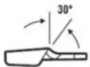
TOP PLATE FILING ANGLE
Correct 30 degrees – File holders are marked with guide marks to align file properly to produce top plate angle.
Less than 30 degrees – for cross cutting.
More than 30 degrees – feathered edge dulls quickly.
CORRECT TOP PLATE FILING ANGLE
INCORRECT TOP PLATE FILING
ANGLE
LESS THAN
30°
MORE THAN
30°
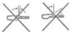
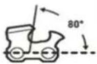
SIDE PLATE ANGLE
Correct - 80 degrees produced automatically if correct diameter file is used in file holder.
Hook – “Grabs” and dulls quickly. Increases potential of kickback. Results from using a file with a diameter too small or file held too low.
Backward Slope – Needs too much feed pressure, causes excessive wear to bar and chain. Results from using a file with a diameter too large, or file held too high.
CHAIN TENSION AND MAINTENANCE
CORRECT SIDE
PLATE FILING
ANGLE
INCORRECT SIDE PLATE
FILING ANGL

BACKWARD
SLOPE

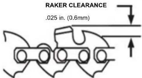
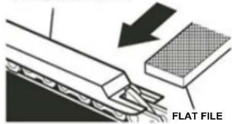
DEPTH GAUGE CLEARANCE
The depth gauge should be maintained at a clearance of .025 in. (0.6 mm). Use a depth gauge tool for checking the depth gauge clearances.
Every time the chain is filed, check the depth gauge clearance.
Use a flat file and a depth gauge jointer to lower all gauges uniformly. Depth gauge jointers are available in .020 in. to .035 in. (0.5 mm to 0.9 mm). Use a .025 in. (0.6 mm) depth gauge jointer. After lowering each depth gauge, restore original shape by rounding the front. Be careful not to damage adjoining drive links with the edge of the file.
Depth gauges must be adjusted with the flat file in the same direction the adjoining cutter was filed with the round file. Use care not to contact cutter face with flat file when adjusting depth gauges.
DEPTH GAUGE JOINTER
flowchart
graph TD
    A["Vehicle 1"] --> B["Vehicle 2"]
    B --> C["Output"]
RESTORE ORIGINAL SHAPE BY ROUNDING THE FRONT
MAINTENANCE
BEFORE USING: Fill oil well with new quality bar and chain oil. Unused SAE30 weight motor oil may be substituted.
If you drop the product, carefully inspect it for damage. If the blade is bent or cracked, handles broken or if you see any other condition that may affect the product's operation, it must be repaired before putting it back into use. Call our customer service help line at 1-800-633-1501 for assistance.
CAUTION: Do not at any time let brake fluids, gasoline, petroleum based products, penetrating oils, etc., come in contact with plastic parts. They contain chemicals that can damage, weaken or destroy plastic.
Make sure the unit is detached from the power supply, then use only mild soap and a damp cloth to clean the tool. Never let any liquid get inside the tool; never immerse any part of the tool into a liquid.
IMPORTANT: To assure product SAFETY and RELIABILITY, repairs, maintenance and adjustment should be performed by a qualified individual using identical replacement parts only.
Ensure that the plastic bar covers are in place when storing.
For smooth and fast cutting, chain needs to be maintained properly. The chain requires sharpening when the wood chips are small and powdery, the chain must be forced through the wood during cutting, or the chain cuts to one side. Refer to instructions earlier in this manual for instructions on properly sharpening the chain.
LUBRICATION SYSTEM FOR POLE/CHAIN SAW
The chain is automatically lubricated.
Use only new bar and chain oil or unused SAE 30 weight motor oil may be substituted. Never use wasted oil, low quality oil, or insufficient oil. This could damage the pump; the bar and the chain which may result in serious personal injury.
Check oil level before each work session, refill if less than 14 full. If the lubrication system does not work properly, check if all oil-ways are clean and free from obstructions. If it is still not working, call our customer service help line at 1-800-633-1501 for assistance.
GUIDE BAR MAINTENANCE
When the guide bar shows signs of wear, reverse it on the saw to distribute the wear for maximum bar life. The bar should be cleaned every day of use and checked for wear and damage.
Feathering or burring of the bar rails is a normal process of bar wear. Such faults should be smoothed with a file as soon as they occur.
A bar with any of the following faults should be replaced.
- Wear inside the bar rails which permits the chain to lay over side ways.
- Bent guide bar
- Cracked or broken rails
- Spread rails
In addition, guide bars with a sprocket at their tip must be lubricated frequently with a grease syringe to extend the guide bar life. Using a grease syringe, lubricate weekly in the lubricating hole.
Turn the guide bar and check that the lubrication holes and chain groove are free from obstructions.
STORAGE
Store the tool in a dry, clean area out of reach of children.
During extended periods of storage, ensure that the tool is protected against corrosion and rust.
At the end of the season, or if the tool is not being used for longer than a month, wipe over all metal surfaces with an oil impregnated cloth to protect them from corrosion or spray with a fine coat of oil.
TROUBLE SHOOTING
Problem Possible Cause Possible Solution
| — Unit does not run | — Extension cord not connected to the plug | — Check extension cord is fully connected to tool |
| — Cord not connected to power source | — Check extension cord is fully connected to a live receptacle | |
| — Trigger switch not fully operated | — Check that safety lock of button is fully depressed prior to moving trigger | |
| — Bar and chain running hot and smoking | — Check chain tension for over-tight condition | — Adjust chain tension |
| — Chain oil tank empty | — Fill tank with chain oil | |
| — Chain installed in wrong direction | — Reverse chain so that cutters face the right direction | |
| — Motor runs but chain is not rotating | — Chain tension too tight | — Adjust chain tension |
| — Check guide bar and chain for damage | — Replace damaged bar and chain with identical replacement parts. |
PARTS AND SERVICE
For parts or service, please call 1-800-633-1501 or visit us online at www.americanlawnmower.com. Be sure to provide all relevant information when you call or visit.
REPAIR PARTS (KITS/ ITEMS)
The model number of this tool is found on a plate or label attached to the housing. Please record the serial number in the space provided below.
MODEL NUMBER PS44008
SERIAL NUMBER
Always mention the model number when ordering kits/items for this tool.
| No. | Kit/ Item Number Description | |
| 1 | PS0810-SCA-1 | Sprocket cover assembly kit |
| 2 | PS08-BCK-1 | 8” Bar and chain assembly kit |
| 3 | PS0810-PAK-1 | Pole assembly kit |
| 4 | PS0810-RHK-1 | Rear handle kit |
CALL US FIRST !!
Call us first with questions about operating or maintaining your product at 1.800.633.1501 between 8:00 a.m. – 5:00 p.m. Eastern Standard Time, or get assistance on www.americanlawnmower.com.
OWNER'S MANUAL
ELECTRIC POLE SAW
Copyright. All Rights Reserved.
Model PS44008
WARRANTY POLICY
Two (2) year limited warranty on Earthwise outdoor equipment.
Earthwise warrants to the original owner that each new product and service part is free from defects in materials and workmanship and agrees to repair or replace any defective product or part for the warranty period as stated above from the original date of purchase except for the conditions and circumstances listed below:
This warranty applies only to the original purchaser at retail and may not be transferred.
Warranty applies if the product is used for personal, household or family use. Warranty is void if product is used for commercial, industrial or rental purposes.
Warranty does not include repairs necessary due to operator's abuse or negligence (including overloading the product beyond capacity or immersion in water), or the failure to assemble, operate, maintain or store the product according to the instructions in the owner's manual.
This warranty is not transferable and only applies to product sold directly from an authorized retailer. This warranty does not apply to any product, new or used, purchased through unauthorized third-party channels.
ANY INCIDENTAL, INDIRECT OR CONSEQUENTIAL LOSS, DAMAGE, OR EXPENSE THAT MAY RESULT FROM ANY DEFECT, FAILURE OR MALFUNCTION OF THE PRODUCT IS NOT COVERED BY THE WARRANTY. Some states do not allow the exclusion or limitation on how long an implied warranty lasts, so the above limitation may not apply to you.
Products sold damaged or incomplete, sold "as is", or sold as reconditioned are not covered under the warranty.
Damage or liability caused by shipping, improper handling, improper assembly, incorrect voltage, improper wiring, improper maintenance, improper modification or the use of accessories and/or attachments not specifically recommended is not covered by this warranty.
Expendable items that become worn during normal use are not covered by the warranty, including, but not limited to guide bar and chain.
Warranty does not cover damage caused by cold, heat, rain, excessive humidity, corrosive environments and materials, or other contaminants.
Warranty does not include installation, assembly or normal adjustments explained in the owner's manual.
The expense of delivering the product to the vendor and the expense of returning the product or replacement parts to the owner is not covered by the warranty.
The warranty does not cover normal deterioration of the exterior finish, including but not limited to scratches, dents, paint chips or any corrosion or discoloration caused by heat, abrasive and chemical cleaners.
Proof of purchase, original dated sales receipt, must accompany all warranty claims.

American Lawn Mower Company
The Great States Corporation
7444 Shadeland Station Way
Indianapolis, IN 46256 USA
Phone 1-800-633-1501
www.americanlawnmower.com
MANUAL DEL OPERARIO
MOTOSIERRA TELESCÓPICO ELÉCTRICA
natural_image
Mechanical tool with long-handled chain, no visible text or symbols
Intertek
5006496

natural_image
Close-up of a handheld electronic device with labeled parts A and B, showing internal components and an arrow indicating direction (no readable text or symbols beyond labels)natural_image
Close-up of a mechanical tool with labeled points A and B, showing a curved arrow indicating motion (no text or symbols beyond labels)natural_image
Close-up of a mechanical component with arrows pointing to features, no visible text or symbolsnatural_image
Close-up of a mechanical component with a circular feature and an arrow pointing to a section (no visible text or symbols)natural_image
Close-up of a mechanical component with curved arrows indicating motion, labeled B and A (no text or symbols beyond labels)ASAMBLEA DE POLE Y MANGO
natural_image
Close-up of a cable connector with labeled points A and B, showing internal components (no text or symbols beyond labels)natural_image
Close-up of a mechanical device with labeled components (A and B) and directional arrows indicating motion or movement (no readable text or symbols)natural_image
Close-up of a mechanical component with arrows indicating direction (no text or symbols)natural_image
Close-up of a mechanical component with a circular hole and arrow indicator (no visible text or symbols)natural_image
Mechanical chain diagram showing gear and chain components (no text or labels)natural_image
Mechanical assembly diagram showing a chain with a magnified inset highlighting a curved mechanical component (no text or symbols present)American Lawn Mower Company
The Great States Corporation
7444 Shadeland Station Way
Indianapolis, IN 46256
Estados Unidos
natural_image
Close-up of a mechanical tool with a long, straight rod and metal handle (no visible text or symbols)

Intertek 5006496
SPÉCIFICATIONS DU PRODUIT
PS44008
natural_image
Close-up of a mechanical device with labeled parts A and B, showing internal components and an arrow indicating direction (no readable text or symbols beyond labels)natural_image
Close-up of a mechanical tool with labeled points A and B, showing a curved arrow indicating motion (no text or symbols beyond labels)natural_image
Close-up of two mechanical components with arrows pointing to features (no visible text or symbols)natural_image
Close-up of a mechanical component with a circular feature and an arrow pointing to it (no visible text or symbols)natural_image
Close-up of a mechanical component with labeled parts A and B, showing curved arrows indicating motion (no text or symbols beyond labels)ASSEMBLAGE DE MANCHE ET DE POIGNÉE ARRIÈRE
natural_image
Close-up of a cable connector with labeled points A and B, showing mechanical clamping (no text or symbols beyond labels)natural_image
Close-up of a mechanical device with labeled components (no readable text or symbols)natural_image
Close-up of a mechanical component with arrows indicating direction (no text or symbols)natural_image
Close-up of a mechanical component with a circular feature and an arrow pointing to it (no visible text or symbols)natural_image
Diagram of a chain-linking gear with an inset showing gear meshing (no text or symbols)natural_image
Mechanical component diagram showing a chain and gear assembly with an inset circular view of a gear mechanism (no text or symbols)American Lawn Mower Company
The Great States Corporation
7444 Shadeland Station Way


- GENERAL POWER TOOL SAFETY WARNINGS
- WARNING: Read all safety warnings and instructions.
- Save all warnings and instructions for future reference.
- Work area safety
- Electrical safety
- Personal safety
- Power tool use and care
- Service
- POLE SAW SAFETY WARNINGS
- PRODUCT SPECIFICATIONS
- PS44008
- ASSEMBLY
- UNPACKING
- PACKING LIST
- POLE AND CUT HEAD ASSEMBLY
- POLE AND HANDLE ASSEMBLY
- DIS-ASSEMBLE POLE AND CUTTING HEAD/HANDLE
- ADJUSTING THE LENGTH OF THE TELESCOPIC POLE
- INSTALLING/REPLACING THE GUIDE BAR AND CHAIN
- TENSIONING THE SAW CHAIN
- OPERATING
- TO TURN THE TOOL ON
- ADJUSTING THE ANGLE OF POLE SAW HEAD
- The following precautions should be followed to minimize
- kickback:
- PROPER CUTTING STANCE
- BASIC CUTTING PROCEDURE
- LIMBING
- PRUNING
- SPRINGPOLES
- CHAIN TENSION AND MAINTENANCE
- CHAIN TENSION
- CHAIN MAINTENANCE
- HOW TO SHARPEN THE CUTTERS
- TOP PLATE FILING ANGLE
- SIDE PLATE ANGLE
- DEPTH GAUGE CLEARANCE
- MAINTENANCE
- LUBRICATION SYSTEM FOR POLE/CHAIN SAW
- GUIDE BAR MAINTENANCE
- STORAGE
- TROUBLE SHOOTING
- PARTS AND SERVICE
- REPAIR PARTS (KITS/ ITEMS)
- CALL US FIRST !!
- OWNER'S MANUAL
- ELECTRIC POLE SAW
- Model PS44008
- WARRANTY POLICY
- MANUAL DEL OPERARIO
- ASAMBLEA DE POLE Y MANGO
- SPÉCIFICATIONS DU PRODUIT
- ASSEMBLAGE DE MANCHE ET DE POIGNÉE ARRIÈRE
Brand : Earthwise
Model : PS44008
Category : Lawn mower