
FP400i - Food Processor Hobart - Free user manual and instructions
Find the device manual for free FP400i Hobart in PDF.

| Product type | Professional food processor |
| Brand | Hobart |
| Model | FP400i |
| Power supply | Three-phase 208-240 V, 50/60 Hz |
| Speeds | 2 speeds: 240 rpm (position 1) and 480 rpm (position 2) |
| Main functions | Slicing, chopping, grating, julienne and dicing (vegetables, fruits, cheese) |
| Base material | Stainless steel |
| Approximate weight | 30 kg (estimate) |
| Dimensions (W x D x H) | Approximately 50 x 40 x 60 cm (estimate) |
| Included accessories | Base unit only (manual pusher, loading hopper and 4-tube accessory sold separately) |
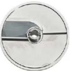
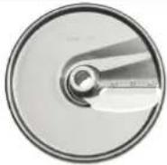
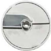
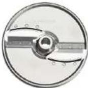
| Compatible cutting discs | Slicing disc, smooth slicing disc, julienne disc, grating disc (for dice/fries), grating disc, shredding disc |
| Safety system | Interlock switches: stop if cylinder unlocked, hopper not installed, pusher not positioned correctly |
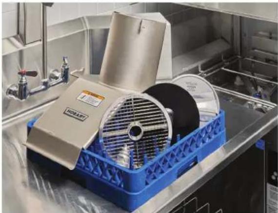
| Cleaning | Removable parts dishwasher safe; wipe exterior with damp cloth |
| Maintenance | Lubricate cutting shaft and hinge pins with a drop of mineral oil; check disc condition |
| Grating discs | Not re-sharpenable, lifespan 8 to 18 months, replacement via Hobart service |
| Installation | Optional wall bracket; two rear wheels for mobility; adjustable feet for leveling |
| Warranty | Contact local Hobart service |
Frequently Asked Questions - FP400i Hobart
User questions about FP400i Hobart
0 question about this device. Answer the ones you know or ask your own.
Ask a new question about this device
Download the instructions for your Food Processor in PDF format for free! Find your manual FP400i - Hobart and take your electronic device back in hand. On this page are published all the documents necessary for the use of your device. FP400i by Hobart.
USER MANUAL FP400i Hobart
MODEL FP300i & FP400i FOOD PROCESSOR
MODEL
FP300i
ML-136363
FP400i
ML-136343
HOBART
701 S. RIDGE AVENUE TROY, OHIO 45374-0001
937 332-3000
www.hobartcorp.com
TABLE OF CONTENTS
GENERAL....3
INSTALLATION 4
Unpacking....4
Location 4
Wall Rack Installation 4
Leveling 4
Electrical Connections....5
Verify Correct Rotation ....5
Start-Up Testing....5
OPERATION 6
Control Switch - FP300i....6
Control Switch - FP400i 6
Assembly Options - FP300i 7
Assembly Options - FP400i 8
Installing Cutting Tools....9
Removing Cutting Tools....9
Feed Cylinder Assembly 10
Feed Hopper Assembly 10
Manual Pusher Plate Assembly....11
Tube Feed Assembly 11
Using the Food Processor....12
Dicing Guide....13
Cutting Tool Guide....14
CLEANING 15
MAINTENANCE 16
Replacement Dicing Grids....16
Service....16
TROUBLESHOOTING 17
Installation, Operation and Care of FP300i & FP400i Food Processor
SAVE THESE INSTRUCTIONS
GENERAL
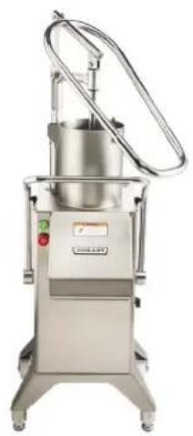
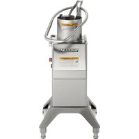
The FP300i and FP400i are used for slicing, shredding, grating, Julienne cutting and dicing vegetables, fruits, or cheese. A wall rack, and a wide range of slicer, shredder, and dicing plates are available accessories.
Food Processors are built for 208-240 volt, 50/60 Hertz, 3 phase electrical supply.
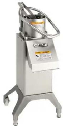
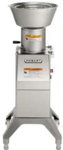
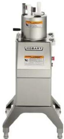
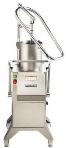
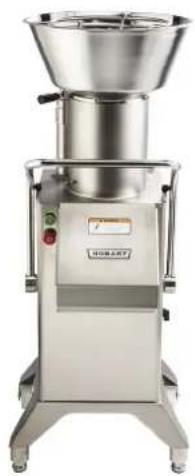
FP300i comes standard with machine base and manual pusher feeder. Feed hopper and 4-tube feed accessories can be purchased separately. FP400i comes standard with the base only. Other accessories including manual push feeder, feed hopper and 4-tube feed must be purchased separately.
natural_image
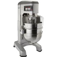
Industrial stainless steel robotic device with control panel and metal frame (no visible text or symbols)Manual Push Feeder Shown With Base
natural_image
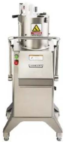
Industrial stainless steel robotic mixer with control panel and label (no readable text or symbols beyond branding)Feed Hopper Assembly 4-Tube Feed
natural_image
Industrial stainless steel robotic device labeled 'HOBART' with control panel and warning label (no readable text beyond branding)Shown With Base
FP300i
natural_image
Exterior view of a stainless steel industrial machine with control panel and rotary arm (no visible text or symbols)Manual Push Feeder Shown With Base
natural_image
Exterior view of a stainless steel industrial mixing press machine (no visible text or symbols)Feed Hopper Assembly 4-Tube Feed
natural_image
Industrial stainless steel industrial machine with warning label and control buttons (no readable text or symbols)Shown With Base
FP400i
INSTALLATION
UNPACKING
The food processor was inspected before leaving the factory. The carrier assumes full responsibility for safe delivery upon acceptance of the shipment. Check for possible shipping damage immediately after receipt.
If the food processor is found to be damaged, complete the following steps:
- Carrier must be notified within five business days of receipt.
- Carrier's local terminal must be notified immediately upon discovery (note the time, date, and who was spoken to), and follow up and confirm with written or electronic communication.
- All original packing materials must be kept for inspection purposes.
- The food processor cannot have been moved, installed, or modified.
- Notify Hobart customer care at (800) 333-7447.
Prior to installing the food processor, verify that the electrical service agrees with the specifications on the machine data plate, which is located on the back of the machine.
Check that the cutting tools are in good condition and are sharp.
LOCATION
Place the food processor in its installation location. Allow adequate space to sides to operate controls and rear to swing the pusher plate feed attachment and open the feed cylinder. The food processor has two rear wheels which allow for easier movement of the device.
WALL RACK INSTALLATION
The wall rack has space for three cutting tools. It is easily mounted on the wall and provides a quick overview of cutting tools and saves space. To install, ensure wall rack is positioned longways (Fig. 1). Top of wall rack is end with the screw hole on the end.
LEVELING
This machine has two front leveling legs and 2 wheels on the back for easy movement in the kitchen space. Turn the adjustable feet to level the machine side-to-side and front-to-back.

Fig. 1
ELECTRICAL CONNECTIONS
WARNING The cutting tools have sharp knives. Use extreme caution when working near knives.
WARNING The electrical cord on this machine is equipped with a four-pronged grounding plug which must be connected properly to a grounded receptacle. If the receptacle isn't properly grounded, then contact an electrician. Do not remove the grounding prong from the plug.
VERIFY CORRECT ROTATION
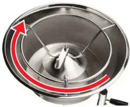
Verify correct rotation of the knife shaft. Make sure it moves in a clockwise direction looking down into the feed cylinder. If the rotation is incorrect, UNPLUG THE ELECTRICAL CORD and interchange any two of the three power supply leads (non-grounding wires) inside the plug. Then, verify that the rotation is correct.
natural_image
Close-up of a stainless steel mixing bowl with a red curved arrow indicating rotation (no text or symbols)START-UP TESTING
- Check that the machine stops when the locking handle is pulled forward, unlocking the feed cylinder (Fig. 2).
- Check that the machine stops when the locking knob for the feed hopper attachment is turned clockwise to the unlocked position, and that the machine restarts when the locking knob is turned counterclockwise to the locked position (Fig. 3).
- Check that the machine stops when the pusher plate feed attachment is swung to the side so that the feed cylinder opening is larger than 1^1/4 " (31.75 mm), and that the machine restarts when the pusher plate feed attachment is swung back over the feed cylinder (Fig. 4).

natural_image
Hand pressing a button on a stainless steel HOBART food processing machine (no visible text or symbols on the machine body)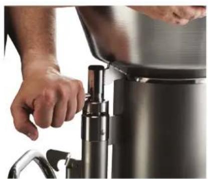
natural_image
Close-up of hands operating a stainless steel water dispenser (no visible text or symbols)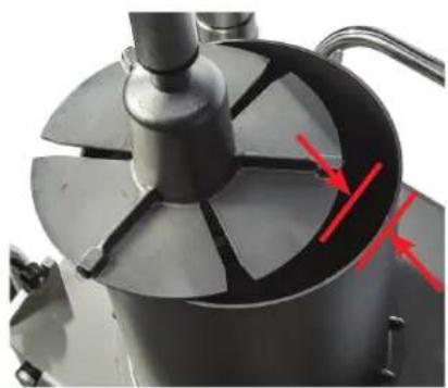
natural_image
Close-up of a mechanical component with a central fan and red arrows indicating direction (no text or symbols visible)If the machine does not perform correctly, call your local Hobart Service Office before using the machine.
OPERATION
Proper assembly of the food processor, including selection of the appropriate cutters, is necessary for correct operation of the food processor. Refer to the CUTTING TOOL GUIDE for sizes of cutters and refer to the appropriate operation instructions.
CONTROL SWITCH - FP300i
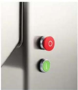
natural_image
Close-up of two control buttons, one red with 'O' and one green with 'I', mounted on a metallic door (no text or symbols visible)Machine has one speed, 500 rpm. Turn on and off using the on and off buttons.
CONTROL SWITCH - FP400i

1 Machine position 1 is low speed (240 rpm) for better results when dicing or when processing soft and juicy products.
2 Machine position 2 is high speed (480 rpm) for most cutting other than dicing.
| FP300i ASSEMBLY OPTIONS | |||
| FP300i machine options | 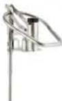 Manual Push Feed** Feed Hopper Assembly 4-Tube Insert Assembly Manual Push Feed** Feed Hopper Assembly 4-Tube Insert Assembly | 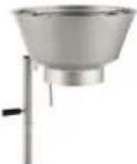 |  |
| Feed cylinder options |  StackingFeed Cylinder for stacking StackingFeed Cylinder for stacking | 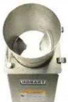 Feed Hopper Cylinder (sold with feed hopper) Feed Hopper Cylinder (sold with feed hopper) | 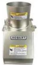 StackingFeed Cylinder for stacking StackingFeed Cylinder for stacking |
| Stainless Tray for Ease of Cleaning |  Tray Tray Tray Tray Tray Tray |  | 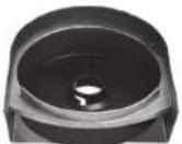 |
| Attachment for securing plates sold with each feed cylinder | [8x70]Decoring Screw Agitator Arm Locking Nut | [15x75] | [7x79] |
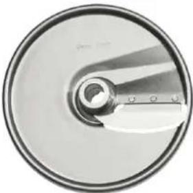
| Julienne, Slice, Shred, Grate Plates Available | 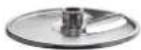 Slicer Plate Slicer Plate Slicer Plate Slicer Plate Slicer Plate Slicer Plate |  |  |
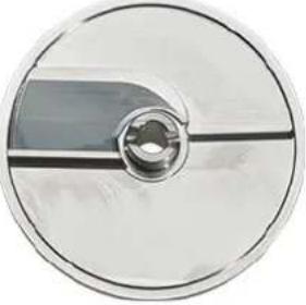
| Dicing Grid French Fry Options Available |  Dicing Plate Dicing Plate Dicing Plate Dicing Plate Dicing Plate Dicing Plate |  |  |
| Standard with FP300i |  Ejector Plate Ejector Plate Ejector Plate Ejector Plate Ejector Plate Ejector Plate |  | 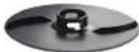 |
| Standard Base for FP300i | 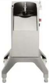 FP300i Base FP300i Base | ||
** Comes standard with base.
| FP400i ASSEMBLY OPTIONS | |||
| FP400i machine options | 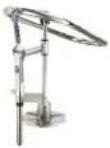 Manual Push Feed Feed Hopper Assembly 4-Tube Insert Assembly Manual Push Feed Feed Hopper Assembly 4-Tube Insert Assembly | 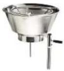 | 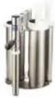 |
| Feed cylinder options | 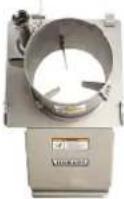 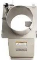 Cutting Stacking Feed Feed Cylinder for cutting or stacking Cutting Stacking Feed Feed Cylinder for cutting or stacking | 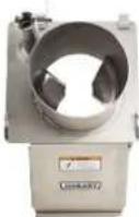 Hopper Cylinder (sold with feed hopper) Hopper Cylinder (sold with feed hopper) |  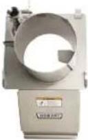 Cutting Stacking Feed Cylinder for cutting or stacking Cutting Stacking Feed Cylinder for cutting or stacking |
| Stainless Tray for Ease of Cleaning | 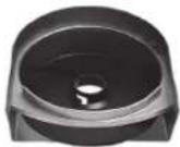 Tray Tray Tray Tray Tray Tray | 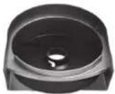 | 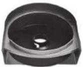 |
| Attachment for securing plates sold with each feed cylinder | [0183]Decoring Screw Agitator Arm Locking Nut | [0203] | [3874] |
| Julienne, Slice, Shred, Grate Plates Available | [KWYDSlicer Plate Slicer Plate Slicer Plate | 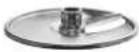 | 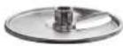 |
| Dicing Grid French Fry Options Available | 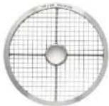 Dicing Plate Dicing Dicing Plate Dicing | 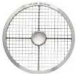 Plate Dicing Plate Plate Dicing Plate | 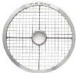 |
| Standard with FP400i | [4KYKEjector Plate Ejector Plate Ejector Plate | 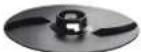 | 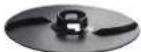 |
| Standard Base for FP400i | 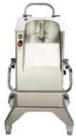 FP400i Base FP400i Base | ||
INSTALLING CUTTING TOOLS
WARNING The cutting tools have sharp knives. Use extreme caution when working near knives.
Always push the red STOP button before changing cutters. The cutting tools have sharp knives. Use extreme caution when working near knives.
- Pull the locking handle all the way open.
- Rotate the feed cylinder up until it locks on the storage handle.
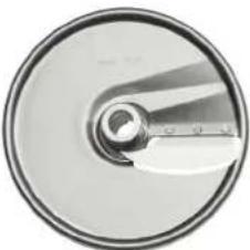
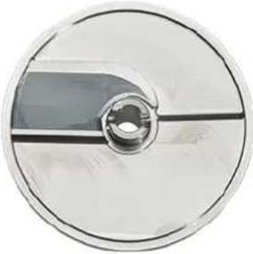
- Lower the ejector plate (Fig. 5) on shaft. Rotate the ejector plate until it seats on the drive pin of the drive shaft. The ejector plate is required for all processing operations.
- When dicing or using the french fry grid, place a suitable dicing grid (see Dice Guide) in the knife chamber. The tray must be used when dicing.
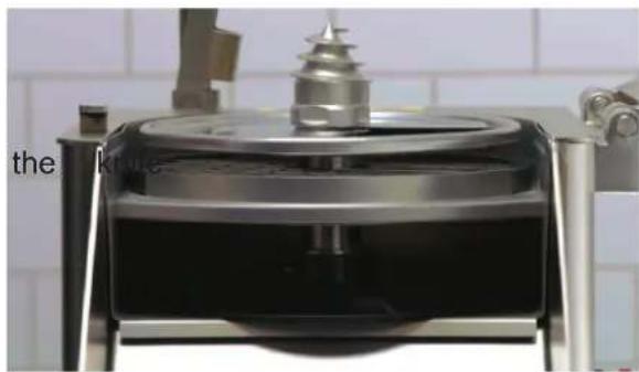
natural_image
Close-up of a metallic mechanical device with a cylindrical top and base, placed on a tiled wall (no visible text or symbols)Fig. 5
- Select the appropriate cutting tool for the job. Place it on the shaft, turning until engaged.
NOTICE When using tube feed assembly, do not use any tools larger than 3/8" (10 mm).
-
Hand tighten the decorating screw, agitator arm or locking nut to secure the blades (see recommended blade locking mechanism in Assembly Options).
-
Release the catch, swing the feed cylinder back into position, and raise the locking handle.
If you use the wrong combination of dicing grid and slicing tool (see Dice Guide), the following may result:
• The feed cylinder cannot be closed.
- The space between the dicing grid and the slicing tool is too large and leads to poor cutting results.
REMOVING CUTTING TOOLS
Always push the red STOP button before changing cutters.
- Pull the locking handle all the way open.
- Rotate the feed cylinder up until it locks on the storage handle.
- Using the wrench supplied, loosen the decorating screw OR the agitator device in a clockwise direction (Fig. 6).
- Remove the cutting tool(s) and the ejector plate.
Interlock switches prevent the food processor from operating when the feed cylinder is out of position, the feed hopper is not installed, the pusher plate or 4-tube insert is not in the feed cylinder. If these features do not function as described, contact your local Hobart Service Office.
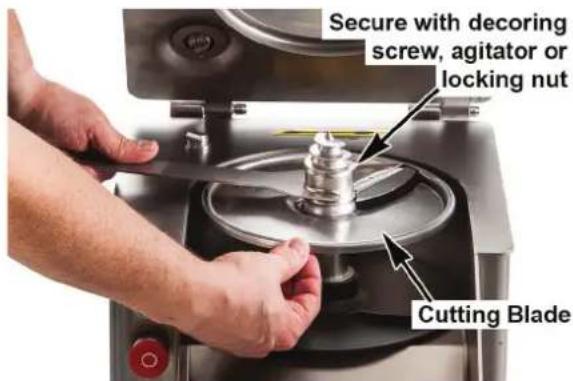
Fig. 6
FEED CYLINDER ASSEMBLY
NOTICE Use the appropriate blade securing attachment shown in assembly options.
- Always press the stop button before working on the machine, even if the machine is not running.
- Pull the locking handle all the way open (Fig. 7).
NOTE: The FP300i does not have a locking handle. Use the locking switch (Fig. 8).
3. Position the feed cylinder onto the hinge pins of the machine and lower into position (Fig. 7).
4. Close the locking handle.
5. When removing the feed cylinder, first remove the feed hopper, pusher plate, or 4-tube insert attachment.
6. Pull the locking handle forward.
7. Raise and remove the feed cylinder from the hinge pins of the machine.
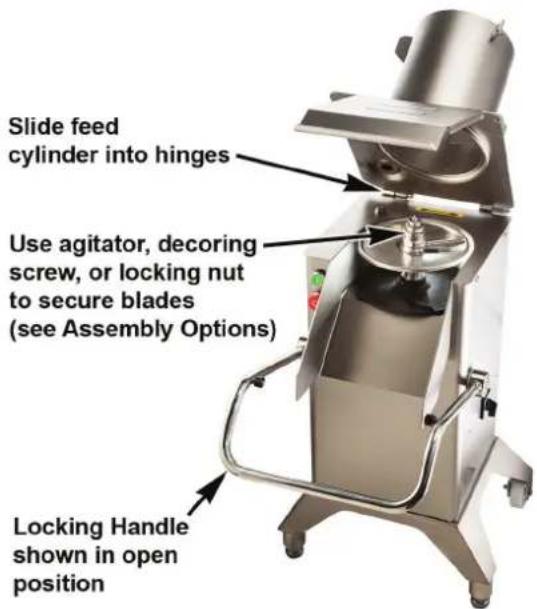
Fig. 7

Fig. 8
FEED HOPPER ASSEMBLY
NOTICE Use the agitator arm to secure the cutting tools to the knife shaft (Fig. 9).
- Always press the stop button before working on the machine, even if the machine is not running.
- Feed hopper cylinder with two vanes to be used with feed hopper only (Fig. 9).
- Place the feed hopper in the center of the feed cylinder tube (Fig. 10).
- Press down the feed hopper and turn the locking knob counter-clockwise (Fig. 11).
- When removing hopper, turn the locking knob clockwise and remove the feed hopper (Fig. 12).
natural_image
Four-panel image showing a hand operating a stainless steel mixing press machine, with no visible text or symbols.Fig. 9 Fig. 10 Fig. 11 Fig. 12
MANUAL PUSHER PLATE ASSEMBLY
NOTICE Use the decorating screw to secure the cutting tools to the knife shaft (Fig. 13).
WARNING The cutting tools have sharp knives. Use extreme caution when working near knives.
- Always press the stop button before working on the machine, even if the machine is not running.
- Use Cutting or Stacking Feed Cylinder with decorating screw for assembly with manual push feed.
- Move the pusher plate handle up. Then insert the pusher plate shaft into feed cylinder tube (Fig. 14).
- Press the pusher plate attachment down and turn the locking knob counterclockwise (Fig. 15).
- When removing, press the stop pad down, swing the pusher plate attachment out clockwise and remove (Fig. 16).
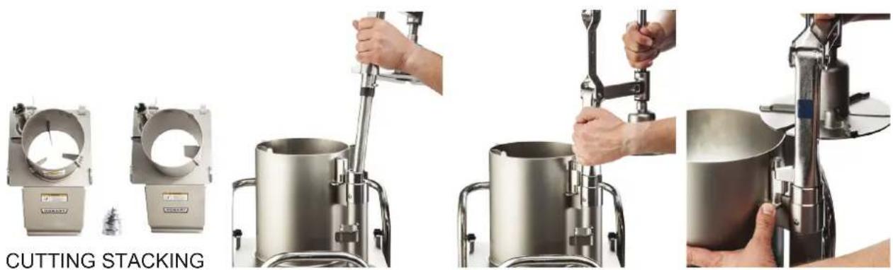
natural_image
Four-panel image showing a metal mixing machine with hands operating the cutter, labeled 'CUTTING STACKING' (no technical text or symbols on the devices themselves)Fig. 13 Fig. 14 Fig. 15 Fig. 16
Photos showing FP400i
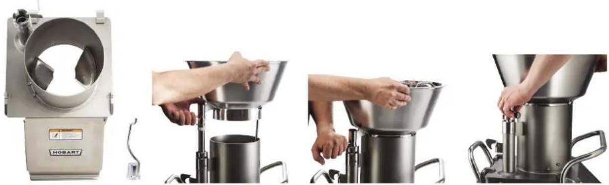
TUBE FEED ASSEMBLY
NOTICE Use the locking nut to secure cutting tools to knife shaft (Fig. 17).
WARNING The cutting tools have sharp knives. Use extreme caution when working near knives.
- Always press the stop button before working on the machine, even if the machine is not running.
- Use Cutting or Stacking Feed Cylinder with locking nut for assembly with 4-tube insert.
- Fit the 4-tube insert into the cylinder, while aligning the tube shaft (Fig. 18) into the feed cylinder tube.
- Press the 4-tube insert attachment down and turn the locking knob counterclockwise (Fig. 19).
- When removing, turn the locking knob clockwise, raise and remove the insert attachment (Fig. 20).
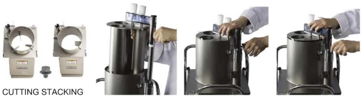
natural_image
Four-panel image showing a cutting stacker machine with hands operating it, no visible text or symbols on the machines themselves.Fig. 17 Fig. 18 Fig. 19 Fig. 20
Photos showing FP400i
USING THE FOOD PROCESSOR
When using the feed hopper attachment, bulk product may be added to the feed hopper during operation (Fig. 21).

natural_image
Top-down view of a metal kitchen pot containing a cluster of potatoes, with a metal stand and green leaf visible (no text or symbols)Fig. 21
When using the pusher plate feed attachment, place prepared products, such as potatoes, carrots, onion, lettuce, cabbage, etc., in the feed cylinder (Fig. 22).
When cutting French fries with the Julienne cutter, place/pile the potatoes against one of the internal guides (Fig. 22). The potatoes may be to cut several at one time. For consistent results, stack product against the internal guide of the feed cylinder, one pile only.
To slice round products, such as lemons and tomatoes, position the product against the partition wall of the feed cylinder (Fig. 22). For best results, it is advisable to remove tops and tails from products like lemons, limes, or onions and place them in the feed cylinder perpendicular to the desired cut.
A light pressure on the pusher plate is all that is required to give the best cutting results.
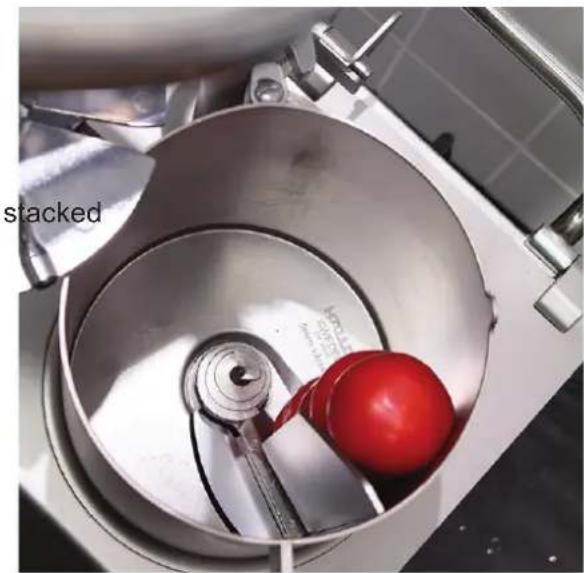
natural_image
Interior view of a stainless steel mixing bowl with a red ball inside, no visible text or symbolsFig. 22
DICING GUIDE
| FP300i/FP400i Food Processor Dice Guide | |||||||||||||
| S35DICE-7/32 (6 mm) | S35DICE-9/32 (8 mm) | S35DICE-3/8 (10 mm) | S35DICE-1/2 (12 mm) | S35DICE-1/2L (12 mm) | S35DICE-5/8 (15 mm) | S35DICE-5/8L (15 mm) | S35DICE-3/4 (20 mm) | S35DICE-3/4L (20 mm) | S35DICE-1 (25 mm) | S35DICE-1L (25 mm) | SFRY-3/8 (10 mm) | ||
 | 3SLICE-1/32 (1 mm) | ||||||||||||
| 3SLICE-1/16 (1.5 mm) | |||||||||||||
| 3SLICE-1/8 (3 mm) | √ | √ | √ | √ | √ | √ | √ | ||||||
| 3SLICE-5/32 (4 mm) | √ | √ | √ | √ | √ | √ | √ | ||||||
| 3SLICE-7/32 (6 mm) | √ | √ | √ | √ | √ | √ | √ | ||||||
| 3SLICE-5/16 (8 mm) | √ | √ | √ | √ | √ | √ | |||||||
| 3SLICE-3/8 (10 mm) | √ | √ | √ | √ | √ | √ | |||||||
 | 3SFTSLCE-5/16 (8 mm) | √ | √ | √ | √ | √ | √ | ||||||
| 3SFTSLCE-3/8 (10 mm) | √ | √ | √ | √ | √ | √ | |||||||
| 3SFTSLCE-1/2 (12 mm) | √ | √ | √ | √ | |||||||||
| 3SFTSLCE-5/8 (15 mm) | √ | √ | √ | ||||||||||
CUTTING TOOL GUIDE
| Cutting Tool Description Blade Options | ||
 | Slicer:Designed to slice firm products, such as root vegetables etc. Dices when combined with a suitable Dicing Grid. | 3SLICE 1/32" (1 mm) 3SLICE 7/32" (6 mm)3SLICE 1/16" (1.5 mm) 3SLICE 5/16" (8 mm)3SLICE 1/8" (3 mm) 3SLICE 3/8" (10 mm)3SLICE 5/32" (4 mm) |
 | Soft Slicer:Designed to slice soft vegetables, fruits, mushrooms etc. Preferably used when dicing soft products, in combination with a suitable Dicing Grid | 3SFTSLCE-5/16" (8 mm)3SFTSLCE-3/8" (10 mm)3SFTSLCE-1/2" (12 mm)3SFTSLCE-5/8" (15 mm) |
 | Julienne Cutter:CutJulienne of firm products for soups, salads, stews, decorations etc. Suitable to cut slightly curved French fries. | 3JUL-5/64" (2 mm)3JUL-5/32" (4 mm)3JUL-7/32" (6 mm)3JUL-3/8" (10 mm) |
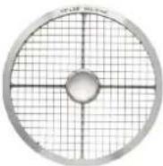 | Dicing Grid:Designed to cut dices in combination with a suitable type of slicer. Dice both hard and soft vegetables, fruits etc.French Fry Grid:Designed to cut straight French fries in combination with a Slicer 3/8" (10 mm) | S35DICE-7/32" (6 mm) S35DICE-5/8L" (15 mm)S35DICE-9/32" (7.5 mm) S35DICE-3/4" (20 mm)S35DICE-3/8" (10 mm) S35DICE-3/4L" (20 mm)S35DICE-1/2" (12 mm) S35DICE-1" (25 mm)S35DICE-1/2L" (12 mm) S35DICE-1L" (25 mm)S35DICE-5/8" (15 mm) SFRY-3/8" (10 mm) |
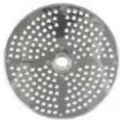 | Grater:Designed to shred various products into strings, such as cheese and cabbage. | 3GRATE-FINE (1.5 mm)3GRATE-CHEESE |
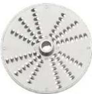 | Shredder:Designed for shredding operations and makes strings of various products, such as cheese and cabbage in the sizes listed. | 3SHRED-1/16" (1.5 mm) 3SHRED-7/32" (6 mm)3SHRED-5/64" (2 mm) 3SHRED-5/16" (8 mm)3SHRED-1/8" (3 mm) 3SHRED-3/8" (10 mm)3SHRED-5/32" (4.5 mm) |
CLEANING
WARNING Turn off the machine and unplug the electrical cord before cleaning.
NOTICE
- Allowing food juices to dry on the machine may cause discoloration.
- DO NOT USE steel wool or sharp objects for cleaning machine surfaces.
- Do not leave the cutting tools in a wet condition when not in use.
Clean the machine immediately after use. Dismantle all removable parts from the machine and wash them in warm water and a mild detergent. Rinse thoroughly and allow to dry. All removable parts can be cleaned in a dishwashing machine. Wipe the exterior of the machine with a damp cloth.
Always store the cutting tools on the wall racks for safe handling and easy access.
To dismantle the machine for cleaning:
- Remove the manual push feed (Fig. 16), feed hopper (Fig. 12) or 4-tube insert (Fig. 20). Clean accessory parts in a 3-compartment sink or with a dishwasher (Fig. 23).
WARNING The cutting tools have sharp knives. Use extreme caution when working near knives.
-
Remove the feed cylinder. The feed cylinder may be removed for cleaning by unscrewing the locking mechanism (Fig. 6) with the wrench provided.
-
Clean removable parts using a 3-compartment sink or with a dishwasher (Fig. 23).
-
Remove the cutting tool.
-
If you have used a dicing grid, before removing, push the remaining leftovers through the TOP of the dicing grid with the nylon brush provided. Pushing the leftovers through from the underside of the dicing grid may damage the grid.
-
Remove the dicing grid and ejector plate; clean plates in a 3-compartment sink or with a dishwasher.
-
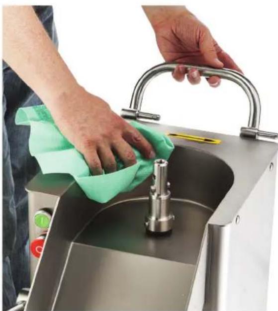
Wipe the knife chamber with a clean damp cloth. Wipe dry with a clean dry cloth (Fig. 24).
-
Return the cutting tools to the wall rack. Lower the ejector plate onto the knife shaft. Press all the way down and turn until the plate is in the locked position.
-
Replace the feed cylinder and feed hopper or pusher plate attachment.
natural_image
Interior view of a stainless steel kitchen appliance with a blue plastic tray and a white rack-mounted fan (no visible text or symbols)Fig. 23
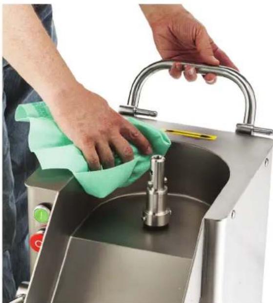
natural_image
Person cleaning a stainless steel kitchen sink with a cloth, no visible text or symbolsFig. 24
MAINTENANCE
⚠ WARNING Turn the machine off and unplug the electrical cord before doing any maintenance.
Routinely inspect the machine to ensure it is in proper working order. Plates must be clean, intact, and sharp.
The knife shaft and the hinge pins should be regularly lubricated with a drop of mineral oil.
NOTICE Do not use cooking oil type products to lubricate the machine.
If the machine develops any problems, contact your local Hobart Service office.
REPLACEMENT DICING GRIDS
Depending on usage, dicing grids become dull from wear with an average life expectancy from 8 to 18 months. Dicing grids cannot be re-sharpened and are therefore expendable. Replacement dicing grids are available from your local Hobart Service Office.
SERVICE
Contact your local Hobart-authorized service office for repairs or adjustments needed on this equipment.
TROUBLESHOOTING
| PROBLEM CAUSE | REMEDY | |
| Machine will not start or stops while operating and won't restart. | Machine plug not installed securely into receptacle. | Make sure machine is securely plugged into receptacle. |
| Feed cylinder not locked in correct position. | Make sure feed cylinder is locked correctly. | |
| Feed hopper locking knob not in correct position. | Turn feed hopper locking knob counterclockwise to the locked position. | |
| Pusher plate feed attachment not in correct position. | Move pusher plate feed attachment to the center of the feed cylinder and lower pusher plate. | |
| Locking handle not in correct position. | Raise the locking handle to the locked position. | |
| Fuse or circuit breaker interrupting power. | Check for blown fuses or fuses with wrong amperage. | |
| Broken wire or connection. | Pull electrical cord from receptacle and call your local Hobart Service Office. | |
| Low output or poor cutting results | Wrong cutting tool used. See | Cutting Tool Guide in this manual. |
| Wrong combination of dicing grid and slicing tool when dicing (space between the two cutting tools is too large). | See Cutting Tool Guide in this manual. | |
| Decoring screw or agitator device not installed. | Install decoring screw or agitator device to the machine. | |
| Problem with blade or grating plate. | Make sure blades or grating plates are intact and sharp. | |
| Speed control switch not in correct position.(FP400i Only) | Place speed control switch in Position 1 for dicing, and in Position 2 for all other cutting. | |
| Feeding pressure too heavy. | Provided the blades and grating plates are sharp, a light pressure is normally all that is required to give the best cutting results. | |
| Build-up under cutting tool, possibly due to ejector plate not in place or container is full. | Make sure the ejector plate is always installed when cutting. | |
| Cutting tool locked to shaft. | Build-up between cutting tool and dicing grid or potato chip grid. | Always use the ejector plate. Use a thick leather glove and carefully rotate cutting tool clockwise. |
| Decoring screw or agitator device cannot be removed. | Devices have tightened during use of the machine. | Use the wrench provided to unscrew devices (left-hand thread). |
PROCESADOR DE ALIMENTOS MODELOS FP300i Y FP400i
MODELOS
FP300i
ML-136363
FP400i
ML-136343
HOBART
701 S. RIDGE AVENUE
TROY, OHIO 45374-0001
937 332-3000
www.hobartcorp.com
TABLA DE CONTENIDO
GENERAL....3
INSTALACIÓN 4
Desembalaje....4
Ubicación......4
Nivelado....4
Interruptor de control - FP300i....6
Interruptor de control - FP400i....6
Opciones de Ensamble - FP300i....7
Opciones de Ensamble - FP400i....8
natural_image
Industrial stainless steel robotic device labeled 'HOBART' with control panel and mounting feet (no visible text beyond label)natural_image
Exterior view of a stainless steel robotic mixer (no visible text or symbols)natural_image
Industrial robotic device labeled 'HOBART' with control panel and mounting base (no readable text beyond label)FP300i
natural_image
Exterior view of a stainless steel industrial mixing machine (no visible text or symbols)natural_image
Exterior view of a stainless steel industrial mixing press machine (no visible text or symbols)natural_image
Exterior view of a stainless steel industrial machine (no visible text or symbols)FP400i
INSTALACIÓN
DESEMBALAJE
natural_image
Close-up of a stainless steel mixing bowl with a red arrow indicating rotation direction (no text or symbols)natural_image
Close-up of a hand pressing down on a stainless steel HOBART kitchen menu (no visible text or symbols beyond branding)
natural_image
Close-up of hands operating a stainless steel water dispenser (no visible text or symbols)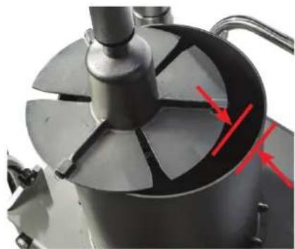
natural_image
Close-up of a mechanical component with a central rotating disc and red arrows indicating direction (no text or symbols visible)natural_image
Close-up of a control panel with red and green buttons (no text or symbols visible)natural_image
Close-up of a metallic mechanical device with a central cylindrical component and a textured top, mounted on a stand against a tiled wall (no visible text or symbols)Fig. 5
natural_image
Four-panel image showing a HOBA Turkey mixing machine, hand pressing a metal bowl, and handling a funnel (no visible text or symbols)Fig. 9 Fig. 10 Fig. 11 Fig. 12
natural_image
Four-panel image showing a hand operating a cylindrical kitchen press machine, with no visible text or symbols.natural_image
Three-panel image showing a laboratory setup with two cylindrical equipment units and hands operating it, labeled 'CORTE APILADO' (no technical text or symbols on the devices themselves)natural_image
Top-down view of a metal kitchen grater containing a pile of potatoes, with a metal tool partially visible (no text or symbols)Fig. 21
natural_image
Close-up of a metal mixing bowl with a red ball inside, no visible text or symbolsFig. 22
| Guía de cubeado del Procesador de Alimentos FP300i/FP400i | |||||||||||||
| S35DICE-7/32 (6 mm) | S35DICE-9/32 (8 mm) | S35DICE-3/8 (10 mm) | S35DICE-1/2 (12 mm) | S35DICE-1/2L (12 mm) | S35DICE-5/8 (15 mm) | S35DICE-5/8L (15 mm) | S35DICE-3/4 (20 mm) | S35DICE-3/4L (20 mm) | S35DICE-1 (25 mm) | S35DICE-1L (25 mm) | SFRY-3/8 (10 mm) | ||
 | 3SLICE-1/32 (1 mm) | ||||||||||||
| 3SLICE-1/16 (1.5 mm) | |||||||||||||
| 3SLICE-1/8 (3 mm) √ √ | √ √ | √ | √ | √ | |||||||||
| 3SLICE-5/32 (4 mm) √ √ | √ | √ √ | √ | √ | |||||||||
| 3SLICE-7/32 (6 mm) √ √ | √ | √ √ | √ | √ | |||||||||
| 3SLICE-5/16 (8 mm) √ √ | √ | √ √ | √ | ||||||||||
| 3SLICE-3/8 (10 mm) √ √ | √ | √ √ | √ | ||||||||||
 | 3SFTSLCE-5/16 (8 mm) √ | √ | √ √ | √ | √ | ||||||||
| 3SFTSLCE-3/8 (10 mm) √ | √ | √ √ | √ | √ | |||||||||
| 3SFTSLCE-1/2 (12 mm) √ | √ | √ √ | |||||||||||
| 3SFTSLCE-5/8 (15 mm) √ | √ | √ | |||||||||||
natural_image
Industrial kitchen equipment with blue plastic tray and stainless steel casing (no visible text or symbols)Fig. 23
natural_image
Person cleaning a stainless steel kitchen sink with a cloth, no visible text or symbolsFig. 24
MANTENIMIENTO
Installation du support mural ....4
Nivellement....4
natural_image
Industrial stainless steel robotic device labeled 'HOBART' with control panel and mounting legs (no visible text beyond label)natural_image
Industrial stainless steel robotic mixer with control panel and mounting base (no visible text or symbols)natural_image
Industrial robotic device labeled 'HOBART' with control panel and mounting base (no readable text beyond label)FP300i

natural_image
Exterior view of a stainless steel industrial mixing machine (no visible text or symbols)natural_image
Exterior view of a stainless steel industrial mixing press machine (no visible text or symbols)natural_image
Exterior view of a stainless steel industrial machine (no visible text or symbols)FP400i
INSTALLATION
DÉBALLAGE
natural_image
Close-up of a stainless steel mixing bowl with red arrows indicating direction (no text or symbols)TEST DE MISE EN MARCHE
natural_image
Hand placing a small object on a HOBART kitchen menu (no visible text or symbols beyond the label)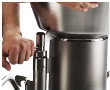
natural_image
Close-up of hands operating a stainless steel water dispenser with a digital valve (no visible text or symbols)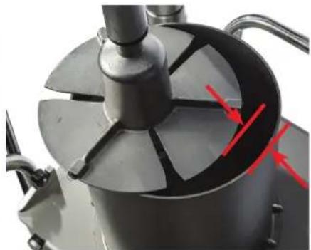
natural_image
Close-up of a mechanical device with a central rotating fan and red arrows pointing to internal components (no visible text or symbols)natural_image
Close-up of a control panel with red and green buttons (no text or symbols visible)natural_image
Close-up of a metallic mechanical device with a central cylindrical component and a textured top, set against a tiled wall background (no visible text or symbols)Fig. 5
natural_image
Four-panel image showing a robotic bread maker in action, with hands operating the funnel and a person adjusting it (no visible text or symbols)Fig. 9 Fig. 10 Fig. 11 Fig. 12
ASSEMBLAGE DU DISPOSITIF DE POUSSÉE MANUEL
AVIS
natural_image
Four-panel image showing a Découpe superposition machine with hands operating it, no visible text or symbols on the devices themselves.natural_image
Top-down view of a metal kitchen grater containing a pile of potatoes, with a metal tool partially visible (no text or symbols)Fig. 21
natural_image
Close-up of a metal mixing bowl with a red ball inside, no visible text or symbolsFig. 22
GUIDE POUR COUPE EN DÉS
| Guide pour coupe en dés du robot culinaire FP300i/FP400i | |||||||||||||
| S35DICE-7/32 (6 mm) | S35DICE-9/32 (8 mm) | S35DICE-3/8 (10 mm) | S35DICE-1/2 (12 mm) | S35DICE-1/2L (12 mm) | S35DICE-5/8 (15 mm) | S35DICE-5/8L (15 mm) | S35DICE-3/4 (20 mm) | S35DICE-3/4L (20 mm) | S35DICE-1 (25 mm) | S35DICE-1L (25 mm) | SFRY-3/8 (10 mm) | ||
 | 3SLICE-1/32 (1 mm) | ||||||||||||
| 3SLICE-1/16 (1,5 mm) | |||||||||||||
| 3SLICE-1/8 (3 mm) | √ | √ | √ | √ | √ | √ | |||||||
| 3SLICE-5/32 (4 mm) | √ | √ | √ | √ | √ | √ | |||||||
| 3SLICE-7/32 (6 mm) | √ | √ | √ | √ | √ | √ | |||||||
| 3SLICE-5/16 (8 mm) | √ | √ | √ | √ | √ | ||||||||
| 3SLICE-3/8 (10 mm) | √ | √ | √ | √ | √ | ||||||||
 | 3SFTSLCE-5/16 (8 mm) | √ | √ | √ | √ | √ | |||||||
| 3SFTSLCE-3/8 (10 mm) | √ | √ | √ | √ | √ | ||||||||
| 3SFTSLCE-1/2 (12 mm) | √ | √ | √ | ||||||||||
| 3SFTSLCE-5/8 (15 mm) | √ | √ | √ | ||||||||||
natural_image
Industrial kitchen appliance with blue plastic tray and stainless steel casing, no visible text or symbolsFig. 23

natural_image
Person cleaning a stainless steel kitchen sink with a cloth, no visible text or symbolsFig. 24
ENTRETIEN
REPLACEMENT DES DISQUES GRILLES


- MODEL FP300i & FP400i FOOD PROCESSOR
- TABLE OF CONTENTS
- GENERAL....3
- INSTALLATION 4
- OPERATION 6
- CLEANING 15
- MAINTENANCE 16
- TROUBLESHOOTING 17
- Installation, Operation and Care of FP300i & FP400i Food Processor
- GENERAL
- INSTALLATION
- UNPACKING
- LOCATION
- WALL RACK INSTALLATION
- LEVELING
- ELECTRICAL CONNECTIONS
- VERIFY CORRECT ROTATION
- START-UP TESTING
- OPERATION
- CONTROL SWITCH - FP300i
- CONTROL SWITCH - FP400i
- INSTALLING CUTTING TOOLS
- WARNING The cutting tools have sharp knives. Use extreme caution when working near knives.
- NOTICE When using tube feed assembly, do not use any tools larger than 3/8" (10 mm).
- REMOVING CUTTING TOOLS
- FEED CYLINDER ASSEMBLY
- FEED HOPPER ASSEMBLY
- MANUAL PUSHER PLATE ASSEMBLY
- TUBE FEED ASSEMBLY
- USING THE FOOD PROCESSOR
- CUTTING TOOL GUIDE
- CLEANING
- WARNING Turn off the machine and unplug the electrical cord before cleaning.
- NOTICE
- MAINTENANCE
- REPLACEMENT DICING GRIDS
- SERVICE
- PROCESADOR DE ALIMENTOS MODELOS FP300i Y FP400i
- TABLA DE CONTENIDO
- INSTALACIÓN 4
- INSTALACIÓN
- DESEMBALAJE
- MANTENIMIENTO
- DÉBALLAGE
- TEST DE MISE EN MARCHE
- ASSEMBLAGE DU DISPOSITIF DE POUSSÉE MANUEL
- AVIS
- ENTRETIEN
- REPLACEMENT DES DISQUES GRILLES
Brand : Hobart
Model : FP400i
Category : Food Processor