Zetta 440 - Receiver Ram Audio - Free user manual and instructions
Find the device manual for free Zetta 440 Ram Audio in PDF.
Download the instructions for your Receiver in PDF format for free! Find your manual Zetta 440 - Ram Audio and take your electronic device back in hand. On this page are published all the documents necessary for the use of your device. Zetta 440 by Ram Audio.
USER MANUAL Zetta 440 Ram Audio
The exclamation point inside an equilateral triangle indicates the existen- ce of internal components whose substi- tution may affect safety. The lightning and arrowhead symbol warns about the presence of uninsula- ted dangerous voltage. To avoid fire or electrocution risk do not expose the unit to rain or moisture. To avoid electric shock, do not open the unit. No user serviciable parts inside. In the case of disfunction, have the unit checked by qualified agents. Class I device. CAUTION
1.2 Main Characteristics
2 Controls: Where and What?
3 Installation and Operation
3.1.2 Bridge Channel Mode
4 Technical Specifications
are registered trade- marks of C.E. Studio-2 s.l.. All other names are trademarks of their respec- tive companies. 0 Sicherheitshinweise 1 Allgemeine Anweisungen
TABLE DES MATIÈRES 2The ZETTA Series, is the result of an in depth study, in order to reach the best compromise between economy and performances, taking advantage of lat- est improvements in automated mixed surface mount and through hole elec- tronic assembly. ZETTA Series are a project based on an up-side-down mono-block approach offering an all-in-one power module that contains the entire amplifier assembly. Simplicity and effectiveness run hand by hand through the entire design to obtain an effectively skilled and work- able product. The last generation QuantaPulse™ switching power supply allows to reach a new level of refined sensing and con- trol of the power flow.
- Unmatched audio quality hi efficiency Class H design
- 2/4 Channels models from 1000W up to 4000W
- Power Management System (PMS™) and Clip Limiter (ICL™)
- Up-side-down design to avoid fan dust acumulation
- Industry standard Neutrik® XLR and Speakon® connectors
- Dual or bridge mode operation
- Temperature controlled, back to front cooling fan
1.2 Main Characteristics
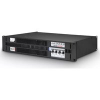
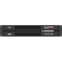
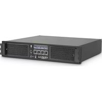
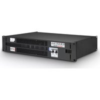
See Figure Signal attenuation level control knobs: Permit independent control of each channel’s attenuation (21 steps). SIGNAL: This LED indicates pre- sence of signal at the inputs. PMS : LED indicating PMS in opera- tion (see page 11). CLIP: LED indicating Intelligent Clip Limiter in operation. Main Power Switch: Position I: Connects the amplifier's current feed. (Blue LED on). Position O disconnects the Power.
Front PanelSee Figure Signal Input: Female Neutrik
XLR Connectors for the amplifier’s signal input. Speaker connectors: Neutrik
Speakon to connect the speakers. Dual / Bridge Operation Selection Switch. To control the level in Bridge mode use the CH-A level knob. Mains Power Cord: to connect the amplifier to the mains network. The colour code is: Blue: Neutral Brown: Live, single phase Yellow-green: Protective Earth
1The Power switch must always be on the “Off” position before plugging the amp to a properly earthed mains sock- et (170-265V AC). The colour code is: Blue: Neutral Brown: Live, single phase Yellow-green: Protective Earth The input signal fed to the amplifier can be either balanced or un-balanced. The drawing below describes both ways to wire an XLR connector for the purpose. Balanced Signal: Connect pin 1 to Ground, pin 2 to Signal + (hot) and pin 3 to Signal - (cold). Unbalanced Signal: Connect Pin 1 to Ground, pin 2 to Signal and pin 3 to Ground. Important!: If a connection is done with a un-balanced line and pin 3 on the XLR is not connected to ground, a 6 dB loss occurs in the line and only a quar- ter of the amplifier power is produced. The amplifiers provides, for each chan- nel, a female XLR Connector (Signal Input) paralleled to a male XLR to daisy chain several amplifiers with the same signal line (LINK).
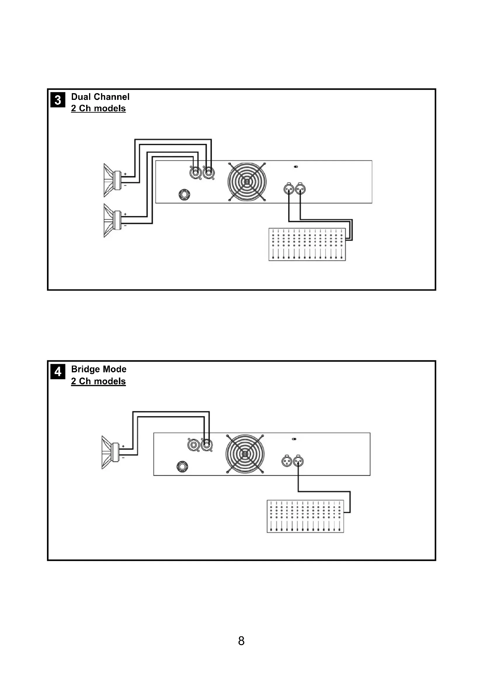
6Installation and Operation Installation et mise en service The amplifier can operate on two differ- ent configurations: DUAL, or BRIDGE. The connections for the two modes are different. See Figure - Set the Amplifier Mode to “DUAL”. - Connect the signal lines to the female XLR connectors on all channels. - Connect the speakers’ lines to the cor- responding Speakon on the amp respecting the polarity. - Use the level control knob on the front panel to adjust each channel indepen- dently. - Each signalling LED group will show its corresponding channel status. See Figure - Set the configuration mode to “BRIDGE” - Connect a signal line to input female XLR Channel “A” (or Ch-C in 4 chan- nel models). - Connect the speaker line to the Channel A Speakon (or Ch-C in 4 channel models) wired to +1 and -2. In this way pin +1 is positive. - Use Channel-A (or Ch-C in 4 channel modes) control knob to adjust the amp’s output. - The signalling LED groups will show the single channel status. WARNING! The “
“ pins, do not have to be Ground!
“ pins, do not have to be Ground!
Bridge Mode 2 Ch models3 Dual Channel 4 Channel models 4 Channel models
Bridge Mode Bridge + Dual Mode 3 Channels Mode 9In the event of incorrect connection or misfunctioning, the amp will activate one or more of its LED to warn about the problem. Correct function: SGNL lights to indi- cate signal presence. ICL: The Intelligent Clip Limiter is ope- rating (see page 10). No Signal: No Input Signal is reaching the amp. Overheating: The amplifier has rea- ched the maximum operational tempe- rature. Most common cause is: the nor- mal air flow is blocked, accumulated dirt, dust or object leaning against the grill. Check and clean periodically. PMS: Several causes can trigger this LED, most common are: - The amplifier is in power-on sequence, where output is inhibited until the amp circuits are ready to operate. - The internal temperatures rise to near thermal shutdown point due to unfa- vourable operating conditions. - Excessive current consumption.
Anschluss und Inbetriebnahme CLIP CLIP CLIP CLIP CLIP CLIP CLIP CLIP CLIP CLIP CLIP CLIP CLIP CLIP CLIP PMSSGNL PMSSGNL PMSSGNL PMSSGNL PMSSGNL PMSSGNL PMSSGNL PMSSGNL PMSSGNL PMSSGNL PMSSGNL PMSSGNL PMSSGNL PMSSGNL PMSSGNLThis is a complete set of protections that monitors the main amp parameters (load status, signal input, temperature, current, etc.) in order to draw from the power sup- ply only the precise amount of current required to maintain safe operation during hazardous or extreme working conditions. This system controls the amount of power that the amp delivers under three basic circumstances: 1.- The power-on sequence, where output is inhibited until the amp circuits are ready to operate. This routine is repeated at every restart, not just when the power switch is activated. 2.- When internal temperatures rise to near thermal shutdown point due to unfavourable operating conditions. Here the system takes control, restricting cur- rent so as to maintain operational continu- ity at the precise power level which the amp is capable of withstanding at that par- ticular moment. 3.- Excessive current consumption. This event only occurs either under laboratory conditions (long term sinusoidal signal testing with dummy loads) or, for example, in field applications in conditions of pro- longed acoustic howl-round. Here PMS takes control to avoid any damage to the speakers and to prevent the mains break- er from tripping or the fuses blowing. The RAM Audio ICL2 is an anticlip system to avoid speaker failure and provide more acceptable sound quality even when clip- ping occurs. With the ICL2 system you don't lose the music “punch” but the speakers are kept under control. SOA Sentry protection effectively limiting the power that the amp could deliver into an incorrect load or to a direct short-cir- cuit. This avoids power transistor failure. PMS