ZETTA 4100 - Receiver Ram Audio - Free user manual and instructions
Find the device manual for free ZETTA 4100 Ram Audio in PDF.
User questions about ZETTA 4100 Ram Audio
0 question about this device. Answer the ones you know or ask your own.
Ask a new question about this device
Download the instructions for your Receiver in PDF format for free! Find your manual ZETTA 4100 - Ram Audio and take your electronic device back in hand. On this page are published all the documents necessary for the use of your device. ZETTA 4100 by Ram Audio.
USER MANUAL ZETTA 4100 Ram Audio
Professional Power Amplifiers
ZETTASeries
210-215-220-236
420-430-440
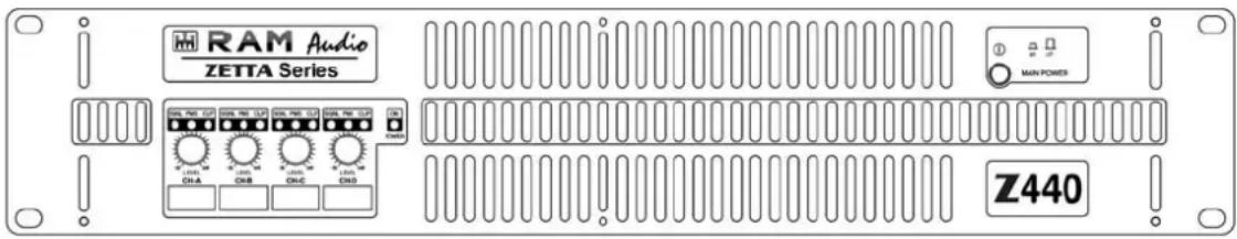
text_image
RAM Audio ZETTA Series MIN PONES Z440OPERATION MANUAL
NOTICE D'EMPLOI
BEDIENUNGSANLEITUNG
SAFETY PRECAUTIONS
SICHERHEITSHINWEISE
AVERTISSEMENTS
WARNING:
ACHTUNG!:
RÈGLES DE SÉCURITÉ:

The exclamation point inside an equilateral triangle indicates the existence of internal components whose substitution may affect safety.

The lightning and arrowhead symbol warns about the presence of uninsulated dangerous voltage.

To avoid fire or electrocution risk do not expose the unit to rain or moisture.
To avoid electric shock, do not open the unit. No user serviciable parts inside. In the case of disfunction, have the unit checked by qualified agents.
Class I device.
VORSICHT
0 Safety Precautions
1 General Information
1.1 Introduction
1.2 Main Characteristics
2 Controls: Where and What?
2.1 Front Panel
2.2 Rear Panel
3 Installation and Operation
3.1 Connections
3.1.1 Dual Channel Mode
3.1.2 Bridge Channel Mode
3.2 Troubleshooting
4 Technical Specifications
4.1 Protection Systems
4.2 Data
©2014 by C.E. Studio-2 s.l.
Pol.Ind. La Figuera
C/Rosa de Luxemburgo n°34
46970 Alaquas - Valencia - SPAIN
Phone: +34 96 127 30 54
Fax: +34 96 127 30 56
http://www.ramaudio.com
e-mail: support@ramaudio.com
P-5435-634 QXPDQXDoc 7/14
RAM Audio ^® , PMS ^™ , SSP ^™ , ICL ^™ and QuantaPulse ^™ are registered trademarks of C.E. Studio-2 s.l.. All other names are trademarks of their respective companies.
1.1 Introduction
The ZETTA Series, is the result of an in-depth study, in order to reach the best compromise between economy and performances, taking advantage of latest improvements in automated mixed surface mount and through hole electronic assembly.
ZETTA Series are a project based on an up-side-down mono-block approach offering an all-in-one power module that contains the entire amplifier assembly. Simplicity and effectiveness run hand by hand through the entire design to obtain an effectively skilled and workable product.
The last generation QuantaPulse ^™ switching power supply allows to reach a new level of refined sensing and control of the power flow.
1.2 Main Characteristics
- Unmatched audio quality hi efficiency Class H design
- 2/4 Channels models from 1000W up to 4000W
- Ultra light weight 6kg, compact package 25cm deep
- Last generation QuantaPulse™ switch mode power supply
- Power Management System (PMS™) and Clip Limiter (ICL™)
- Up-side-down design to avoid fan dust accumulation
- Industry standard Neutrik® XLR and Speakon® connectors
- Comprehensive protection set (ICL, PMS, SSP, turn-on, Temp, DC....)
• Detented sealed potentiometers - Dual or bridge mode operation
- Temperature controlled, back to front cooling fan
Controls: Where and What?
1 Signal attenuation level control knobs: Permit independent control of each channel's attenuation (21 steps).
2 SIGNAL: This LED indicates presence of signal at the inputs.
PMS : LED indicating PMS in operation (see page 11).
CLIP: LED indicating Intelligent Clip Limiter in operation.
3 Main Power Switch: Position I: Connects the amplifier's current feed. (Blue LED on). Position O disconnects the Power.
2.1 Frontplatte
Siehe Fig. 1
text_image
SGNL PMS CLIP SGNL PMS CLIP SGNL PMS CLIP SGNL PMS CLIP SGNL PMS CLIP ON POWER LEVEL CH-A LEVEL CH-B LEVEL CH-C LEVEL CH-D 2 1 3
text_image
① on off MAIN POWER 3Controls: Where and What?
1 Signal Input: Female Neutrik® XLR Connectors for the amplifier's signal input.
2 Speaker connectors: Neutrik®
Speakon to connect the speakers.
3 Dual / Bridge Operation Selection Switch. To control the level in Bridge mode use the CH-A level knob.
□ Mains Power Cord: to connect the amplifier to the mains network. The colour code is:
Blue: Neutral
Brown: Live, single phase
Yellow-green: Protective Earth
2.2 Rückplatte
Siehe Fig. 2
Installation and Operation
The Power switch must always be on the "Off" position before plugging the amp to a properly earthed mains socket (170-265V AC). The colour code is:
Blue: Neutral
Brown: Live, single phase
Yellow-green: Protective Earth
The input signal fed to the amplifier can be either balanced or un-balanced. The drawing below describes both ways to wire an XLR connector for the purpose.
Balanced Signal: Connect pin 1 to Ground, pin 2 to Signal + (hot) and pin 3 to Signal - (cold).
Unbalanced Signal: Connect Pin 1 to Ground, pin 2 to Signal and pin 3 to Ground.
3.1 Anschlüsse
Brown: Live, single phase
Yellow-green: Protective Earth
Brown: Live, single phase
Yellow-green: Protective Earth
Important!: If a connection is done with a un-balanced line and pin 3 on the XLR is not connected to ground, a 6 dB loss occurs in the line and only a quarter of the amplifier power is produced.
The amplifiers provides, for each channel, a female XLR Connector (Signal Input) paralleled to a male XLR to daisy chain several amplifiers with the same signal line (LINK).
Installation and Operation
The amplifier can operate on two different configurations: DUAL, or BRIDGE. The connections for the two modes are different.
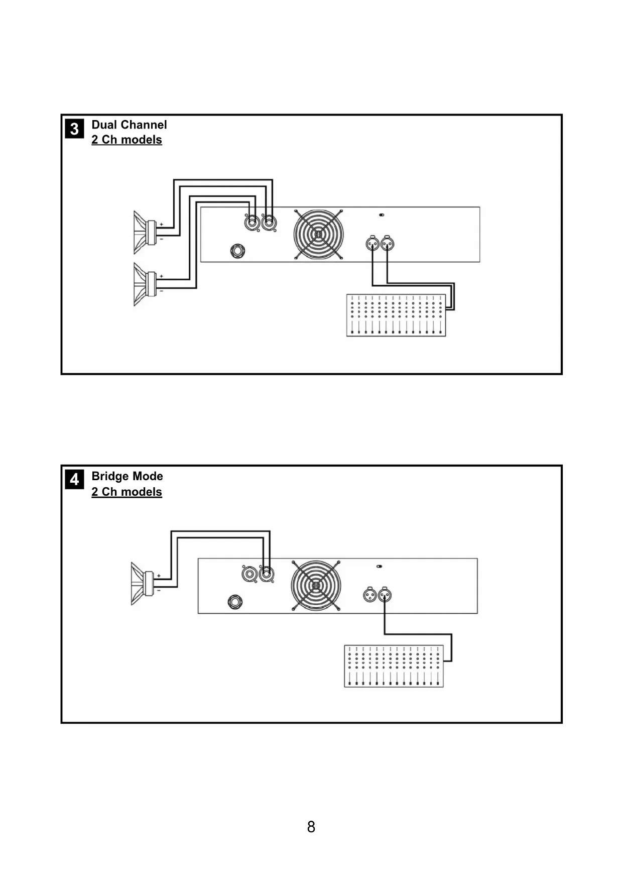
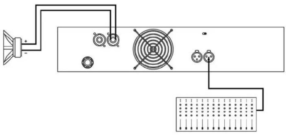
3.1.1 DUAL Channel Mode
See Figure 3
- Set the Amplifier Mode to "DUAL".
- Connect the signal lines to the female XLR connectors on all channels.
- Connect the speakers' lines to the corresponding Speakon on the amp respecting the polarity.
- Use the level control knob on the front panel to adjust each channel independently.
- Each signalling LED group will show its corresponding channel status.
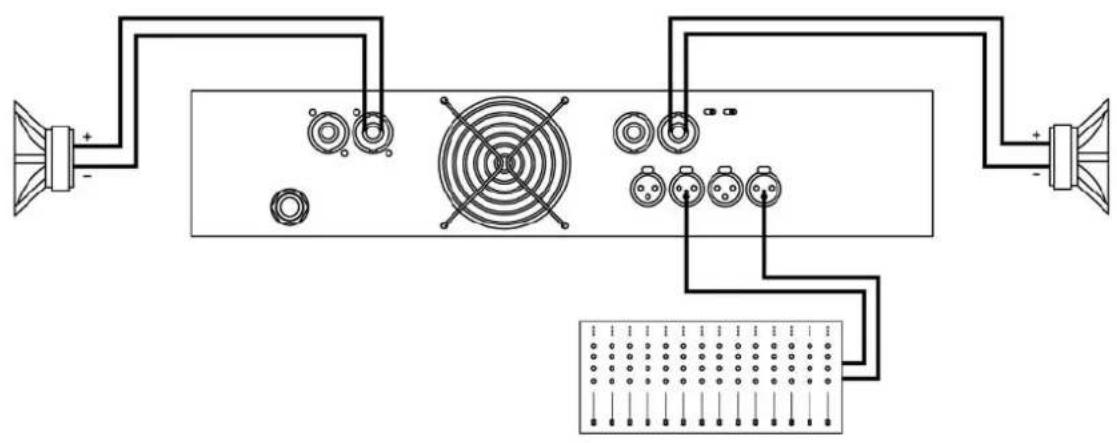
3.1.2 BRIDGE Channel Mode
See Figure 4
- Set the configuration mode to "BRIDGE"
- Connect a signal line to input female XLR Channel "A" (or Ch-C in 4 channel models).
- Connect the speaker line to the Channel A Speakon (or Ch-C in 4 channel models) wired to +1 and -2. In this way pin +1 is positive.
- Use Channel-A (or Ch-C in 4 channel modes) control knob to adjust the amp's output.
- The signalling LED groups will show the single channel status.
WARNING! The “-” pins, do not have to be Ground!
ACHTUNG! The “-” pins, do not have to be Ground!
natural_image
Pure electrical circuit lines without any symbols4
Bridge Mode
2 Ch models
text_image
Diagram showing audio connection with speaker, speaker fan, and connector pinout for a device3
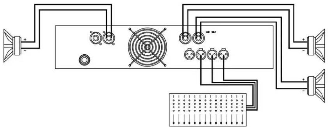
Dual Channel
4 Channel models

natural_image
Pure electrical circuit lines without any symbols4
Bridge Mode
4 Channel models
text_image
Diagram of an electronic device with speaker, fan, and panel connections showing signal routing and component layoutBridge + Dual Mode
3 Channels Mode
text_image
Electrical wiring diagram showing connections between speaker, fan, and panel with labeled componentsInstallation and Operation
In the event of incorrect connection or misfunctioning, the amp will activate one or more of its LED to warn about the problem.
3.2 Problemlösung
Correct function: SGNL lights to indicate signal presence.

ICL: The Intelligent Clip Limiter is operating (see page 10).

No Signal: No Input Signal is reaching the amp.

Overheating: The amplifier has reached the maximum operational temperature. Most common cause is: the normal air flow is blocked, accumulated dirt, dust or object leaning against the grill. Check and clean periodically.

PMS: Several causes can trigger this LED, most common are:

This is a complete set of protections that monitors the main amp parameters (load status, signal input, temperature, current, etc.) in order to draw from the power supply only the precise amount of current required to maintain safe operation during hazardous or extreme working conditions.
This system controls the amount of power that the amp delivers under three basic circumstances:
1.- The power-on sequence, where output is inhibited until the amp circuits are ready to operate. This routine is repeated at every restart, not just when the power switch is activated.
2.- When internal temperatures rise to near thermal shutdown point due to unfavourable operating conditions. Here the system takes control, restricting current so as to maintain operational continuity at the precise power level which the amp is capable of withstanding at that particular moment.
3.- Excessive current consumption. This event only occurs either under laboratory conditions (long term sinusoidal signal testing with dummy loads) or, for example, in field applications in conditions of prolonged acoustic howl-round. Here PMS takes control to avoid any damage to the speakers and to prevent the mains breaker from tripping or the fuses blowing.
ICL2 ^™ - Intelligent Clip Limiter
The RAM Audio ICL2 is an anticlip system to avoid speaker failure and provide more acceptable sound quality even when clipping occurs. With the ICL2 system you don't lose the music "punch" but the speakers are kept under control.
SSP™ - SOA Sentry Protection
SOA Sentry protection effectively limiting the power that the amp could deliver into an incorrect load or to a direct short-circuit. This avoids power transistor failure.
PMS™ - Power Management System
SSP™ - SOA Sentry Protection
SSP™ - SOA Sentry Protection
Technical Specifications
Technical Specifications
| Z-210 Z-215 Z-220 Z-236 Z-420 Z-430 Z-440 | |||||||
| Max. Output Power | |||||||
| @ 2Ω | 2x 500 W | 2x 750 W | 2x 1000 W | 2x 1800 W | 4x 500 W | 4x 750 W | 4x 1000 W |
| @ 4Ω | 2x 400 W | 2x 700 W | 2x 1000 W | 2x 1750 W | 4x 400 W | 4x 700 W | 4x 1000 W |
| @ 8Ω | 2x 240 W | 2x 450 W | 2x 650 W | 2x 950 W | 4x 220 W | 4x 450 W | 4x 630 W |
| Bridge @ 4Ω | 1000 W | 1500 W | 2000 W | 3600 W | 2x 1000 W- | 2x 1500 W | 2x 2000 W |
| Bridge @ 8Ω | 800 W | 1400 W | 2000 W | 3500 W | 2x 800 W | 2x 1400 W | 2x 2000 W |
| Frequency Response | |||||||
| Power Bandwidth ±0.25dB | 20Hz-20kHz | ||||||
| Phase Response | |||||||
| @ 1 watt 20Hz-20kHz | ±15 deg | ||||||
| Total Harmonic Distortion | |||||||
| 20Hz-20kHz | <0.05% | ||||||
| Intermodulation Distortion | |||||||
| SMPTE | <0.05% | ||||||
| Damping Factor | |||||||
| 20-500Hz @8Ω | >500 | ||||||
| Crosstalk | |||||||
| 20Hz-20kHz | >75dB | ||||||
| Voltage Gain | 32dB | ||||||
| Sensitivity | |||||||
| Rated Power (26/32/38dB Gain) | 1.1 V | 1.5 V | 1.8 V | 2.2 V | 1.1 V | 1.5 V | 1.8 V |
| Signal-to-Noise Ratio | |||||||
| 20Hz-20kHz | 101dBA | 103dBA | 104dBA | 105dBA | 101dBA | 103dBA | 104dBA |
| Required AC Mains | |||||||
| Operating Voltage (50Hz-60Hz) | 170V-265V AC | ||||||
| Power On Idling (@230V) | 0.5 A | 0.5 A | 0.5 A | 0.5 A | 0.5 A | 0.5 A | 0.5 A |
| 1/8 Rated Power (@4 ohm) | 3.5 A | 4 A | 5 A | 10 A | 7 A | 8 A | 10 A |
| Dimensions | |||||||
| W x H x D (mm) | 483x88.9x254 | ||||||
| W x H x D (inches) | 19x3.5x10 | ||||||
| Weight | |||||||
| Net (Kg-Lbs) | 5-11 | 5-11 | 6-26.5 | 12-26.5 | 12-26.5 | 12-26.5 | 12-26.5 |
| Protections | |||||||
| Soft-start, Turn-on Turn-off transients, Over-heating, DC, RF, Short-circuit, Open or mismatched loads, ICLTM, PMSTM and SSPTM | |||||||