
W 12004 - Receiver Ram Audio - Free user manual and instructions
Find the device manual for free W 12004 Ram Audio in PDF.
| Product type | 4-channel power amplifier |
| Brand | Ram Audio |
| Model | W 12004 |
| Power supply | 170-265 V AC, single-phase, 50/60 Hz |
| Class | Class I |
| Operating modes | Dual, Link, Bridge |
| Audio inputs | 4 x Neutrik XLR female (balanced/unbalanced) |
| Audio outputs | 2 x Speakon (NEUTRIK) |
| Connectivity | USB for firmware update and DSP control, Ethernet for remote standby |
| LED indicators | SIG, TEMP, PMS, ICL (per channel) |
| Protection systems | PMS (Power Management System), ICL (Intelligent Clipping Limiter), SSP (SOA Sentry Protection) |
| Input attenuators | Detented, independent per channel |
| Sensitivity adjustment | 32 dB (factory) |
| Cooling | Forced ventilation, do not obstruct |
| Maintenance and cleaning | Dust the ventilation grills, do not use abrasive products |
| Safety | Do not expose to rain or moisture, do not open the device, refer servicing to qualified personnel |
| General information | User manual available in PDF, 16 pages |
Frequently Asked Questions - W 12004 Ram Audio
User questions about W 12004 Ram Audio
0 question about this device. Answer the ones you know or ask your own.
Ask a new question about this device
Download the instructions for your Receiver in PDF format for free! Find your manual W 12004 - Ram Audio and take your electronic device back in hand. On this page are published all the documents necessary for the use of your device. W 12004 by Ram Audio.
USER MANUAL W 12004 Ram Audio
Professional Power Amplifiers
6000-9000-12000
9004-9044-12004-12044
WSeries

text_image
AC high-frequency micro-Link Audio Adder 1- Top4SUB 32dB Link+40 dB -3dB -3dB 3dB 0dB W RAM Audio RAM AudioOPERATION MANUAL
NOTICE D'EMPLOI
BEDIENUNGSANLEITUNG

text_image
SAFETY PRECAUTIONS AVE
text_image
SSEMENESTSHINWEISE
natural_image
Completely black image with no visible content or text.WARNING:

text_image
CAUTION RISK OF ELECTRIC SHOCK DO NOT OPENACHTUNG!:

To avoid fire or electrocution risk do not expose the unit to rain or moisture.
To avoid electric shock, do not open the unit. No user servicable parts inside. In the case of disfunction, have the unit checked by qualified agents.
Class I device.
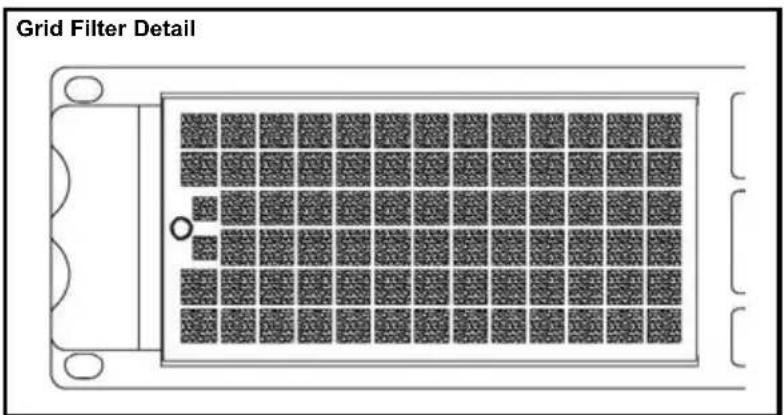
Clean the front panel filters regularly. Extract the filters removing the front panel grid unscrewing the thumbscre-ews placed at the sides of the grid. Clean the filters using water and deter-gent. Place the grid filter introducing first the internal side and screwing the thumbscrew.
IMPORTANT:
Clean the front panel filters regularly. Extract the filters removing the front panel grid unscrewing the thumbscre-ews placed at the sides of the grid. Clean the filters using water and deter-gent. Place the grid filter introducing first the internal side and screwing the thumbscrew.
IMPORTANT:
Clean the front panel filters regularly. Extract the filters removing the front panel grid unscrewing the thumbscre-ews placed at the sides of the grid. Clean the filters using water and deter-gent. Place the grid filter introducing first the internal side and screwing the thumbscrew.
text_image
Grid Filter DetailINDEX
INHALTSVERZEICHNIS
TABLE DES MATIÈRES
0 Safety Precautions
1 General Information
1.1 Introduction
1.2 Main Characteristics
2 Controls: Where and What?
2.1 Front Panel
2.2 Rear Panel
3 Installation and Operation
3.1 Connections
3.1.1 Dual Channel Mode
3.1.2 Link Channel Mode
3.1.3 Bridge Channel Mode
3.2 Configuration
3.3 Troubleshooting
4 Technical Specifications
4.1 Protection Systems
4.2 Data
©2011 by C.E. Studio-2 s.l.
Pol.Ind. La Figuera
C/Rosa de Luxemburgo n°34
46970 Alaquas - Valencia - SPAIN
Phone: +34 96 127 30 54
Fax: +34 96 127 30 56
http://www.ramaudio.com
e-mail: support@ramaudio.com
P-5435-634 QXPDQXDoc 4/11
RAM Audio ^e , PMS ^TM , SSP ^TM , ICL ^TM ,
FCM ^™ and QuantaPulse ^™ are registered trademarks of C.E. Studio-2 s.l..
All other names are trademarks of their respective companies.
General Information
The W Series devices feature two or four channel models, ready for rough handling in the touring world. For this purpose, W Series amps implement oversized high efficiency regulated power supply with PFC front end to deliver their full performances independently of mains status. This together with oversized high efficiency audio power stage, forced front to back cooling through a component-free path with removable front panel dust filters, improved rugged mechanical design with even weight distribution, full digital control from LCD display on the front panel... Resulting in: just power, reliability and robustness for your touring gigs!
1.2 Main Characteristics
- PFC QuantaPulse™ Regulated Dual SMPS
- Digital Control with extra large LCD display user interface
- Channel Temperature and Output Level Monitor in the LCD
- USB port for firmware update and DSP control
- 25 position Gain, Bridge mode, Input Links and ICL, front panel configurable
• Digital Potentiometers with Encoder control
• RAM Audio Power Management System - Hi Efficiency, Heavy Duty Audio Power section for extreme use
- Easily removable front panel dust filters
- Industry standard Neutrik® XLR and Speakon® connectors
- Optional low latency 24bits 96kHz high performance DSP with post-DSP signal links and Ethernet control. It features up to 70 meters input delay.
- Optional EtheRAM II Ethernet monitor and control system
- Optional EtherSound™/CobraNet™ audio transport and AES/EBU Digital input
Controls: Where and What?
Configuration and signal attenuation level control knobs: Permit independent control of each channel's attenuation and change the amplifier configuration. See page 10.
2 SIGNAL: This LED indicates presence of signal at the inputs.
TEMP: This LED shows temperature protection is active.
PMS: LED indicating PMS in operation (see page 13)
ICL: LED indicating Intelligent Clip Limiter in operation (see page 13).
3 Main Power Switch: Position I: Connects the amplifier's current feed. (Blue LED on). Position O disconnects the Power. Position II (optional): Stand-by Mode. The Amp's Power is activated remotely via Ethernet. (Amber LED).
4 Display: See page 10.
5 USB Connector for firmware upgrade and optional DSP control.
2.1 Frontplatte
Siehe Fig. 1
Controls: Where and What?
1 Signal Input: Female Neutrik® XLR Connectors for the amplifier's signal input.
Signal Link: Male Neutrik® XLR Connectors for daisy chaining input signal to other amplifiers (parallel connected to female input connectors).
2 Speaker connectors: Neutrik®
Speakon to connect the speakers.
3 Mains Power Cord: to connect the amplifier to the mains network. The colour code is:
Blue: Neutral
Brown: Live, single phase
Yellow-green: Protective Earth
2.2 Rückplatte
Siehe Fig. 2
text_image
2 OUT CHUB OUT CHB 1 1 2 OUT CHAB OUT CHA CE 20-24V~ 540Hz SN CHB CHC CHD CHD CHD CHD CHD CHD CHD CHD CHD CHD CHD CHD CHD CHD CHD CHD CHD CHD CHD CHD CHD CHD CHD CHD CHD CHD CHD CHD CHD CHD CHD CHD CHD CHDInstallation and Operation
The Power switch must always be on the "Off" position before plugging the amp to a properly earthed mains socket (170-265V AC). The colour code is:
Blue: Neutral
Brown: Live, single phase
Yellow-green: Protective Earth
The input signal fed to the amplifier can be either balanced or un-balanced. The drawing below describes both ways to wire an XLR connector for the purpose.
Balanced Signal: Connect pin 1 to Ground, pin 2 to Signal + (hot) and pin 3 to Signal - (cold).
Unbalanced Signal: Connect Pin 1 to Ground, pin 2 to Signal and pin 3 to Ground.
3.1 Anschlüsse
Brown: Live, single phase
Yellow-green: Protective Earth
Brown: Live, single phase
Yellow-green: Protective Earth
Important!: If a connection is done with a un-balanced line and pin 3 on the XLR is not connected to ground, a 6 dB loss occurs in the line and only a quarter of the amplifier power is produced.
The amplifiers provides, for each channel, a female XLR Connector (Signal Input) paralleled to a male XLR to daisy chain several amplifiers with the same signal line (LINK).
Installation and Operation
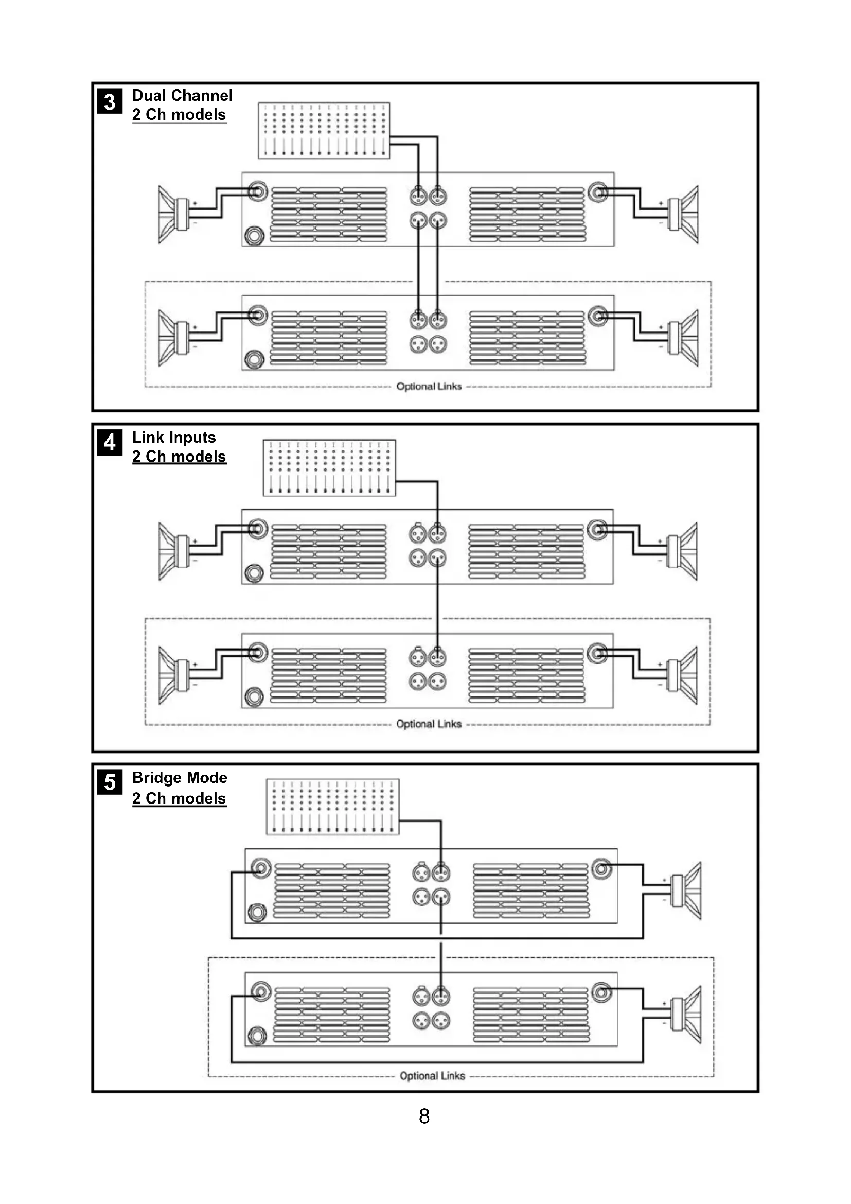
The amplifier can operate on three different configurations: DUAL, LINK or BRIDGE. The connections for the three modes are different.
3.1.1 DUAL Channel Mode
See Figure 3
- Set the Amplifier Mode to "DUAL".
- Select the chosen Gain (Default setting 32dB).
- Connect the signal lines to the female XLR connectors on all channels.
- Connect the speakers' lines to the corresponding Speakon on the amp respecting the polarity.
- Use the level control knob on the front panel to adjust each channel independently.
- Each signalling LED group will show its corresponding channel status.
3.1.2 LINK Channel Mode
See Figure 4
- Operate as Dual Channel Mode with the signal input linked to another adjacent channel.
3.1.3 BRIDGE Channel Mode
See Figure 5
- Set the configuration mode to "BRIDGE" (see page 9).
- Select the chosen Gain (Default setting 32dB).
- Connect a signal line to input female XLR Channel "A" (or Ch-C in 4 channel models).
- Connect the speaker line to the Channel A Speakon (or Ch-C in 4 channel models) wired to +1 and -2. In this way pin +1 is positive.
- Use Channel-A (or Ch-C in 4 channel modes) control knob to adjust the amp's output.
- The signalling LED groups will show the single channel status.
WARNING! The “-” pins, do not have to be Ground!
ACHTUNG! The “-” pins, do not have to be Ground!
text_image
3 Dual Channel 4 Channel models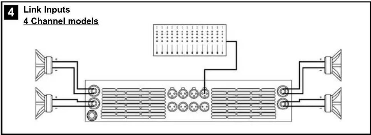
text_image
4 Link Inputs 4 Channel models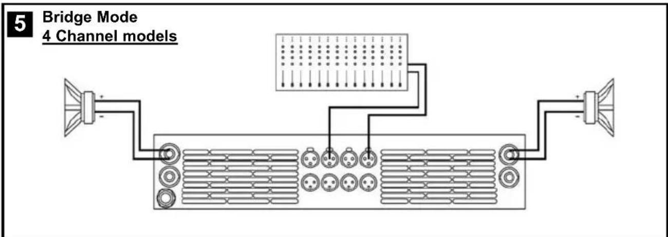
text_image
5 Bridge Mode 4 Channel models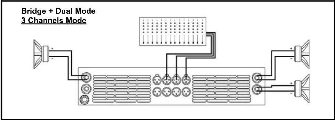
text_image
Bridge + Dual Mode 3 Channels Mode3.2 Configuration

text_image
1-G32dB-Dual-UnLink M 0dB 0dB -3dB -6dBMain Screen: shows the current preset name ("G32dB-Dual-UnLink" as default), and the channel attenuation. As an option you can show the output VUmeter. The "M" appears at the top right corner if the preset has been changed from the last load. You can change each channel amplifier level turning the encoder knob for each channel.
Menu navigation: to access to the Menu screen you have to press the CH-A encoder knob from the Main Screen. Turning the CH-A encoder knob you access to the different options. When you press the CH-A encoder knob you start the Edit mode (only for some options), and a "E" blinking letter appears at the top right corner. Using the four encoder knobs you can change the different options. Pressing another time the CH-A encoder knob you finish the Edit mode, and return to the Menu screen. The last menu option is Exit to return to the main screen or Exit + Dial Lock to protect the encoder knob from any unwanted action. If you use this option you can unlock the system pressing the CH-A knob for 5 seconds. If you need to limit the access to the configuration you can define a password from the Password Manager in the Amplifier Setup section. The Menu development are the next:
Amplifier Setup
| Channel Temperature | |||
| 60% | 50% | 60% | 70% |
Amplifier Setup: You access to the Setup Menu, where you can change parameters as Inputs Link, Gain, Bridge Mode... Also you can change the preset and limit the access using a Password. See Amplifier Setup section on next page for more details.
Channel Temperature: Show the percent of maximum temperature for each channel. When you are near the 100% the PMS system limits the power output to avoid reach the overheating protection.
Display Mode UU meter
Operating Time 45h 34min
Display Mode: Change between Channel Attenuation.or Vu meter mode in the Main Screen.
Operating Time: shows the amplifier total time operation.
Firmware Version Amp Control v1.2b
Firmware Version: shows the Amp Control firmware version. You can upgrade it using the USB port.
Installation and Operation
Amplifier Setup: when you are in the Main Menu and access to the Amplifier Setup section, you can change different amplifier parameters, change the current preset and protect the access using a password. The Menu development for this section is the next:
Preset Manager Load Save Del Rest
Inputs Link IN-A IN-B IN-C IN-D
Amplifier Gain [dB] 32dB 32dB 32dB 32dB
Amplifier Mode BRDG BRDG DUAL DUAL
Attenuators Link Disabled
ICL Clip Limiter Enabled
Password Control Enabled
Preset Manager: you can change quickly the amplifier preset configuration. To access to any option you have to enter in Edit mode (pressing CH-A knob) and turn the corresponding encoder: CH-A for Load, CH-B for Save, CH-C for Delete and CH-D for Restore default. Select a preset number from 0 to 9.
Inputs Link: you can Link the input signal to the next channel. Enter in Edit mode and turn the CH-B, CH-C or CH-D knob to link the input to the previous channel.
WARNING! You have to remove the input connector of the linked channel!
Amplifier Gain: you can change independently the amplifier gain for each channel from 26dB to 38dB (0.5dB steps). Enter in Edit mode and use the corresponding channel knob to modify it.
Amplifier Mode: it configures the amplifier in Dual or Bridge mode. In Edit mode use the CH-A or CH-C channel knob to change the option.
Attenuators Link: you can link all attenuators to modify the output level for all channels simultaneously. When you change this option to Enabled, you modify the attenuation for all channels using any channel knob.
ICL Clip Limiter: you can turn on or turn off the ICL Clip Limiter for all channels. We recommend to you to work with this option enabled to avoid any damage to the speakers.
Password Control: you can define a password to prevent any modification of the amplifier configuration. When you turn on this option, you have to introduce a password using the four knob encoders, and confirm it. After that, you need to introduce this password each time you want to modify the amplifier configuration. There is a generic password which you can use to disable the Password Control, it is: 5 5 5 5
Installation and Operation
In the event of incorrect connection or misfunctioning, the amp will activate one or more of its LED to warn about the problem.
3.3 Problemlösung

Correct function: SGNL lights to indicate signal presence.

ICL: The Intelligent Clip Limiter is operating (see page 10).

No Signal: No Input Signal is reaching the amp.

Overheating: The amplifier has reached the maximum operational temperature. Most common cause is: the normal air flow is blocked, accumulated dirt, dust or object leaning against the grill. Check and clean periodically.

PMS: Several causes can trigger this LED, most common are:
- The amplifier is in power-on sequence, where output is inhibited until the amp circuits are ready to operate.
- The internal temperatures rise to near thermal shutdown point due to unfavourable operating conditions.
- Excessive mains current consumption.
This is a complete set of protections that monitors the main amp parameters (load status, signal input, temperature, current, etc.) in order to draw from the power supply only the precise amount of current required to maintain safe operation during hazardous or extreme working conditions.
This system controls the amount of power that the amp delivers under three basic circumstances:
1.- The power-on sequence, where output is inhibited until the amp circuits are ready to operate. This routine is repeated at every restart, not just when the power switch is activated.
2.- When internal temperatures rise to near thermal shutdown point due to unfavourable operating conditions. Here the system takes control, restricting current so as to maintain operational continuity at the precise power level which the amp is capable of withstanding at that particular moment.
3.- Excessive mains current consumption. This event only occurs either under laboratory conditions (long term sinusoidal signal testing with dummy loads) or, for example, in field applications in conditions of prolonged acoustic howl-round. Here PMS takes control to avoid any damage to the speakers and to prevent the mains breaker from tripping or the fuses blowing.
ICL2™ - Intelligent Clip Limiter
The RAM Audio ICL2 is an anticlip system to avoid speaker failure and provide more acceptable sound quality even when clipping occurs. With the ICL2 system you don't lose the music "punch" but the speakers are kept under control.
SSP™ - SOA Sentry Protection
SOA Sentry protection effectively limiting the power that the amp could deliver into an incorrect load or to a direct short-circuit. This avoids power transistor failure.
FCM™ - Faulty Channel Management
Faulty Channel Management system to avoid entire device shutdown.
PMS™ - Power Management System
FCM™ - Faulty Channel Management
Faulty Channel Management system to avoid entire device shutdown.
PMS™ - Power Management System
FCM™ - Faulty Channel Management
Faulty Channel Management system to avoid entire device shutdown.
Technical Specifications
| W-6000 W-9000 W-12000 W-9004 W-9044 W-12004 W-12044 | |||||||
| Output Power | |||||||
| 1kHz, 1.0% THD+N | |||||||
| @ 2Ω 2x 3025 W 2x 4400 W 2x 5900 W 4x 2260 W - 4x 3025 W - | |||||||
| @ 4Ω | 2x 1600 W | 2x 2300 W | 2x 3100 W | 4x 1150 W | 4x 2200 W | 4x 1600 W | 4x 2950 W |
| @ 8Ω | 2x 820 W | 2x 1200 W | 2x 1600 W | 4x 600 W | 4x 1150 W | 4x 820 W | 4x 1550 W |
| Bridge @ 4Ω | 6050 W | 8800 W | 11800 W | 2x 4520 W | - | 2x 6050 W | - |
| Bridge @ 8Ω | 3200 W | 4600 W | 6200 W | 2x 2300 W | 2x 4400 W | 2x 3200 W | 2x 5900 W |
| Frequency Response | |||||||
| Power Bandwidth ±0.25dB | 20Hz-20kHz | ||||||
| Phase Response | |||||||
| @ 1 watt 20Hz-20kHz | ±15 deg | ||||||
| Total Harmonic Distortion | |||||||
| 20Hz-20kHz | <0.05% | ||||||
| Intermodulation Distortion | |||||||
| SMPTE | <0.05% | ||||||
| Damping Factor | |||||||
| 20-500Hz @8Ω | >500 | ||||||
| Crosstalk | |||||||
| 20Hz-20kHz | >80dB | ||||||
| Voltage Gain | 26dB to 38dB (0.5dB steps) | ||||||
| Sensitivity | |||||||
| Rated Power (26/32/38dB Gain) | 4/2/1 V | 4.9/2.5/1.2 V | 5.7/2.8/1.4 V | 3.5/1.7/0.9 V | 4.8/2.4/1.2 V | 4.1/2/1 V | 5.6/2.8/1.4 V |
| Signal-to-Noise Ratio | |||||||
| 20Hz-20kHz | 113dB | 115dB | 116dB | 112dB | 115dB | 113dB | 116dB |
| Required AC Mains | |||||||
| Operating Voltage (50Hz-60Hz) | 170V-265V AC | ||||||
| Power On Idling (@230V) | 0.5 A | 0.5 A | 0.5 A | 0.5 A | 0.5 A | 0.5 A | 0.5 A |
| 1/8 Rated Power (@230V min. Z) | 7 A | 10 A | 13 A | 11 A | 10 A | 14 A | 13 A |
| Dimensions | |||||||
| W x H x D (mm) | 483x89x460 | ||||||
| W x H x D (inches) | 19x3.5x18.1 | ||||||
| Weight | |||||||
| Net (Kg-Lbs) | 10-22.1 | 12-26.5 | 12-26.5 | 12-26.5 | 12-26.5 | 12-26.5 | 12-26.5 |
Protections
Soft-start, Turn-on Turn-off transients, Muting at turn-on, Over-heating, DC, RF, Short-circuit, Open or mismatched loads, Overloaded power supply, Mains Overvoltage, ICL ^™ , PMS ^™ , SSP ^™ and FCM ^™
