
BQ550 - Vacuum Cleaner BROAN - Free user manual and instructions
Find the device manual for free BQ550 BROAN in PDF.

| Product Type | Central Vacuum (BQ550) |
| Brand | Broan |
| Power Supply | 120 VAC, 15 A, separate branch circuit |
| Bag Capacity | 6 US gallons (22.7 liters) - disposable bag model 391C |
| Filter Type | Disposable bag + motor foam filter |
| Minimum Clearance Dimensions | Min height 45¼ in (115 cm), width 32 7/8 in (83.5 cm), depth 12 in (30.5 cm) from wall |
| Included Hose Length | 30 feet (9.1 m) |
| Included Accessories | Floor brush, round dusting brush, upholstery brush, crevice tool, telescopic wand, hose holder, storage bag |
| Activation | Automatic by hose insertion or hose switch |
| Installation Type | Wall mount (bracket included) |
| Intake Orientation | Adjustable right or left |
| Warranty | 5 years (first 3 years parts and labor) |
| Bag Maintenance | Recommended twice a year |
| Foam Filter Cleaning | Brush or wash with soapy water, dry flat |
| Safety | Grounding required, do not use outdoors or on wet surfaces |
Frequently Asked Questions - BQ550 BROAN
User questions about BQ550 BROAN
0 question about this device. Answer the ones you know or ask your own.
Ask a new question about this device
Download the instructions for your Vacuum Cleaner in PDF format for free! Find your manual BQ550 - BROAN and take your electronic device back in hand. On this page are published all the documents necessary for the use of your device. BQ550 by BROAN.
USER MANUAL BQ550 BROAN
natural_image
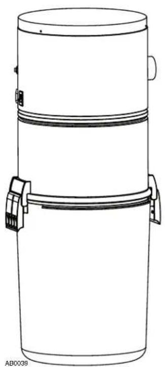
Line drawing of a cylindrical container with two side handles and a handle, labeled 'AB0039' at the bottom (no text or symbols on the diagram itself)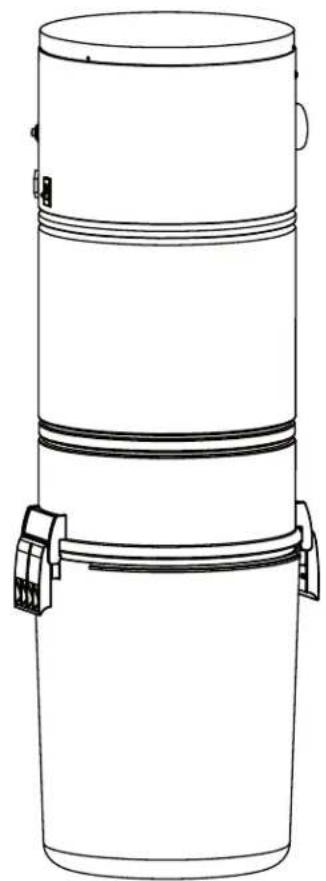
natural_image
Line drawing of a cylindrical container with two side handles and a top lid (no text or symbols)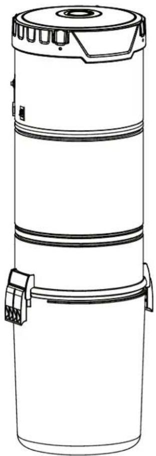
natural_image
Line drawing of a cylindrical industrial device with a lid and two connectors (no text or symbols)MODELS SFDB-DH, SFDB-DI, SFDB-DJ AND SFDB-DT
VENMAR VENTILATION ULC WWW.BROAN.CA 1-877-896-1119

REGISTER YOUR PRODUCT ONLINE AT: WWW.BROAN.CA
IMPORTANT SAFETY INSTRUCTIONS
SAVE THESE INSTRUCTIONS READ ALL INSTRUCTIONS BEFORE USING THIS APPLIANCE
When using an electrical appliance, basic precautions should always be followed, including the following:
WARNING
To reduce the risk of fire, electric shock or injury:
- Do not use on wet surfaces or outdoors.
- Do not vacuum liquids or fine powders (such as drywall dust).
- Do not use to pick up flammable or combustible liquids such as gasoline or use in areas where they may be present.
- Do not pick up anything that is burning or smoking, such as cigarettes, matches, or hot ashes.
- Do not allow to be used as a toy. Close attention is necessary when used by or near children.
- Use only as described in this manual. Use only manufacturer's recommended attachments.
- Keep hair, loose clothing, fingers and all parts of body away from openings and moving parts.
- Turn off all controls before unplugging.
- Use extra care when cleaning on stairs.
- Do not handle plug or appliance with wet hands.
- Do not use with damaged cord or plug. If appliance is not working as it should, if it has been dropped, damaged, left outdoors, or dropped into water, return it to a Service Center.
- Keep your work area well lighted.
- Connect to a properly grounded outlet only. See grounding instructions shown on page 9.
- When performing installation, servicing or cleaning the unit, it is recommended to wear safety glasses and gloves.
- When applicable local regulations comprise more restrictive installation and/or certification requirements, the aforementioned requirements prevail on those of this document and the installer agrees to conform to these at his own expenses.
CAUTION
- Do not put any object into openings. Do not use with any opening blocked; keep free of dust, lint, hair and anything that may reduce air flow.
- Ensure air flows freely and exhausts unobstructed from top or side outlet.
- Do not use without filter (or filters, according to the model) in place.
- Do not use to blow leaves or debris.
- Do not place any object on top of the unit.
- Do not install the unit horizontally.
- Do not use the pail as a wash bucket.
- Do not use the pail as a stool.
- Avoid picking up sharp objects.
- This appliance is for use on a standard 120 VAC, dedicated 15-amp branch circuit. Some brands of house panel breakers may be more sensitive to startup current than others (for example, Square D brand). In the event where nuisance tripping of the house panel breaker occurs*, we recommend changing the breaker with an "HM" type of the same AMP rating.
*after ensuring that the circuit is DEDICATED to the central vacuum unit, meaning that there is no other electrical device connected to the central vacuum unit circuit. - Do not unplug the unit by pulling on cord. To unplug, grasp the plug, not the cord.
- Store your vacuum cleaner indoors in a clean, dry area, and away from extreme temperatures.
- Any servicing other than that recommended in this manual should be performed by an authorized service facility.
- We recommend that your unit be inspected by a specialized technician once a year.
TABLE OF CONTENTS
GENERAL INFORMATION......4
TOOL LISTING....4
WORKING WITH PLASTIC TUBING....4
CUTTING TUBING....4
MAKING A JOINT 4
CEMENTING FLEXIBLE TUBING....4
SECURE WIRE TO TUBING 4
WALL INLET INSTALLATION 4
MAKING THE WALL INLET CUTOUT....4
ATTACHING THE INLET MOUNTING PLATE (V144) 4
COMPLETING THE INLET ASSEMBLY 4
INSTALLING THE INLET (V111) 4
V800W CANSWEEP® UNDER CABINET INSTALLATION 5-6
V800W CANSWEEP® BASEBOARD WALL INSTALLATION ....7
POWER UNIT INSTALLATION 8
LOCATING THE POWER UNIT 8
CHANGING INTAKE LINE DIRECTION....8
MOUNTING THE POWER UNIT 9
FITTING MAIN LINE TO POWER UNIT....10
GROUNDING INSTRUCTIONS .... 10
WIRING....10
DISPOSABLE BAG REPLACEMENT (BQ550 AND BQ500KIT POWER UNITS ONLY) 11
PERMANENT FILTER (BQ650 AND BQ700 POWER UNITS ONLY) 12
REMOVAL AND INSTALLATION OF PERMANENT FILTER (BQ650 AND BQ700 POWER UNITS ONLY) ......12
MOTOR FOAM FILTER (ALL UNITS) 12
REMOVING MOTOR FOAM FILTER....12
REINSTALLING MOTOR FOAM FILTER....12
ACCESSORIES (BQ500KIT ONLY) 13
ACCESSORIES INCLUDED....13
INSTALLING HOSE HANGER....13
TROUBLESHOOTING GUIDE....14
SERVICE PARTS 15
WARRANTY....16
GENERAL INFORMATION WALL INLET INSTALLATION
TOOL LISTING
Depending on the installation, the use of the following tools may be required:
Wire strippers, 1/4" and 1/2" drill bits, utility knife, putty knife, 2½" hole saw, keyhole saw, hammer, cold chisel, level, flashlight, drill, electrical tape, Phillips no. 2 screwdriver, wrench, hacksaw, tape measure, safety glasses.
Power tools are recommended to make the installation proceed quickly. A mask and gloves should be worn when cutting ducting and using glue.
WORKING WITH PLASTIC TUBING
CUTTING TUBING
Measure the length of tube needed. Allow 5/8" of tubing for inserting into fittings and 1½" for placing into flexible tubing. Cut the plastic tubing with a hacksaw, ensuring that the cut is exactly square. Use wire cutters or tin snips to cut flexible tubing, 8" lengths of flexible tubing should not be cut.
Use a small knife or steel wool to remove any burrs from the inside of the tube.
Use a file to slightly bevel the outside of the tube so that it will easily slide into the fitting. Use steel wool or a light grained sandpaper to buff the surface of the tube which will be glued.
MAKING A JOINT
Insert the tube into the fitting, aligning both parts as they will be installed. Mark the tube and the fitting to quickly realign the joint.
Apply cement in an inch-wide band to the outside of the tube. Insert the tube into the fitting with the alignment marks a quarter turn apart, and then quickly push and turn the fitting to align the marks and spread the cement. Allow 1 minute for the joint to dry.
natural_image
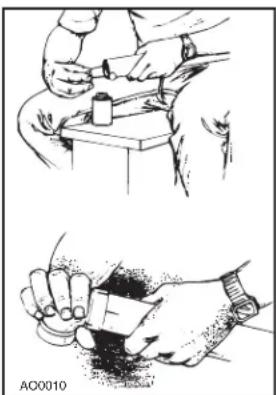
Illustration of two hand tools: one using a tool on a table, the other holding a cup (no text or symbols present)CEMENTING FLEXIBLE TUBING
Ensure the ends of the flexible tubing are even. When joining flexible tubing to plastic tubing or to an inlet mounting plate, apply cement to both the inside of the flexible tubing and the outside of the plastic tubing or mounting plate tubing ring. Twist both pieces while joining them to evenly spread the glue. Allow 5 minutes for the cement to set in flexible tubing.
SECURE WIRE TO TUBING
The low-voltage power wiring is run along with the tubing. Use electrical tape to secure the wire to the tubing. Tape the wire approximately every 12" to 18".
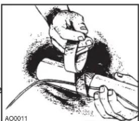
natural_image
Illustration of a person adjusting a device with a cable (no text or symbols visible)MAKING THE WALL INLET CUTOUT
The wall inlet should be located 18" on-center from the floor and directly in line with the attic or basement inlet tubing hole previously drilled in the wall plate or header. The wall inlet cutout must be exactly 3 18 high by 2 78 wide.
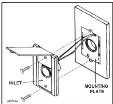
ATTACHING THE INLET MOUNTING PLATE (V144)
Reach through the inlet hole and locate the inlet tubing. Pull the flexible tubing through the inlet hole and remove the low-voltage wiring from inside the tube.
Remove the nail flange from the inlet mounting plate (see illustration at right). Apply cement to both the inside of the flexible tubing and to the outside of the mounting plate's tube ring. Insert the mounting plate's tube ring in the flexible tubing and twisting the pieces as you join them to spread the cement, and align the mounting plate in a vertical position.
natural_image
Technical line drawing of a mechanical housing component with mounting holes and a circular opening (no text or symbols)Now, strip the ends of the two low-voltage wires, and then connect the wires to the screw terminals on the back of the inlet cover. When the wiring is complete, assemble the inlet cover to the tube guard and mounting plate.
COMPLETING THE INLET ASSEMBLY
Once you have attached the mounting plate to the flexible tubing, pull the low-voltage wire through the top wiring hole in the mounting plate.
INSTALLING THE INLET (V111)
Place the inlet into the wall cutout (the inlet cover remains on the outside). Hold the inlet in place and gradually tighten down each screw a little bit at a time.
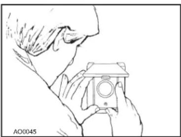
natural_image
Line drawing of a person holding a camera (no text or symbols)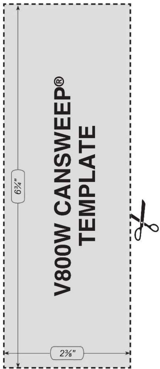
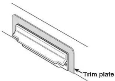
If by any chance the opening was cut too big, a trim plate (part number V801W) is available to provide a perfect cover.
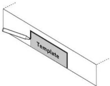
1
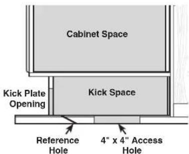
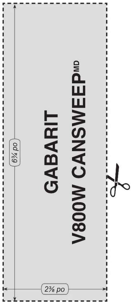
Align the template (cut from this instruction sheet) onto the kick plate to the desired location, and trace the outline of the area.
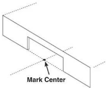
2
Cut out the desired opening and discretely mark the center of the opening on the floor.
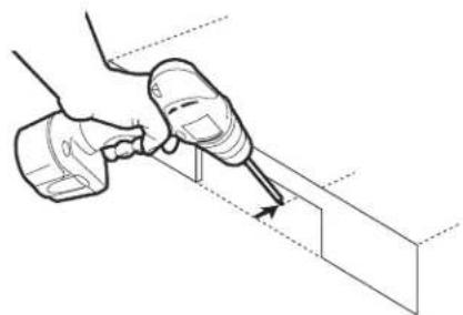
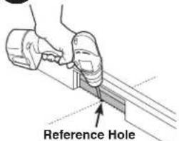
3
Drill a small reference hole along the center line behind the kick plate through the subfloor.
natural_image
Illustration of a hand using a tool to apply or install a component into a 3D block (no text or symbols present)4
Locate the reference hole from beneath the subfloor. Cut a 4" x 4" access hole on your chosen position along the center line under the kick space.
V800W CANSWEEP® UNDER CABINET INSTALLATION (CONT'D)
5
Fig. A

natural_image
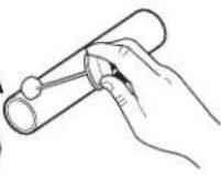
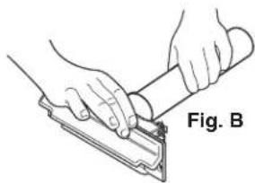
Illustration of hands using a tool to cut or install a mechanical component, labeled 'Fig. B' (no text on diagram itself)Solvent weld a coupling to a piece of 2" central vacuum pipe, long enough to reach the 4" x 4" access hole from the opening on the kick plate (Fig. A).
Friction fit the other end of the coupling to the CanSweep® until secure. Do not glue, friction fit only (Fig. B).
6
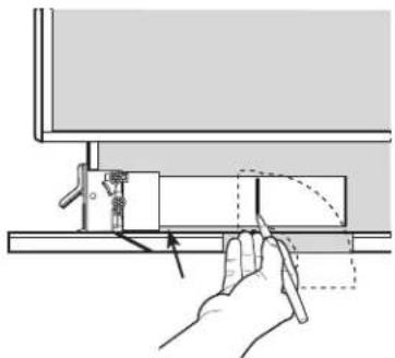
Insert the CanSweep®/pipe into the opening on the kick plate. Use a 90° sweep elbow fitting to determine a cut mark on the other end of the pipe. Then cut the pipe at the mark.
natural_image
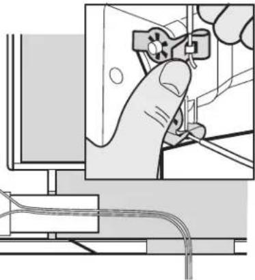
Diagram of a hand operating a mechanical device with a curved arrow indicating motion (no text or symbols present)7
Slide the low voltage wires into the CanSweep® clips as shown to complete the wiring connections.
natural_image
Illustration of a hand operating a switch mounted on a computer monitor (no text or symbols visible)8
Slide the CanSweep®/pipe and low voltage wires into the opening on the kick plate. Glue both ends of the elbow to the piping system, and then secure the
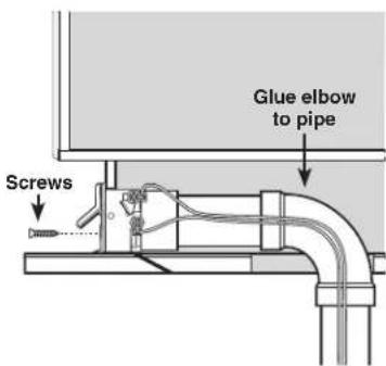
CanSweep® to the kick plate with the 2 supplied screws.
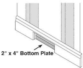
V800W CANSWEEP® BASEBOARD WALL INSTALLATION
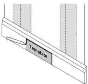
1
Choose a desired position on the baseboard between two studs. Place the template (cut from this instruction sheet) on the position, and trace the outline of the area.
5
Make piping connections as required and ready the short 90° elbow in position behind the CanSweep®.
Make sure that the opening of the elbow will securely attach onto the spigot on the back of the CanSweep ^® when it is time for connection.
2
Trim the opening on the baseboard and through the drywall until reaching the 2" x 4" bottom wall plate.
natural_image
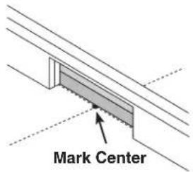
Close-up of hands using a tool to adjust or install a mechanical component (no visible text or symbols)3
Against the edge of the 2" x 4" bottom plate, mark the center of the opening.
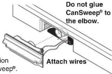
Slide the low volt wires into the CanSweep ^® clips as shown to complete the wiring connections.
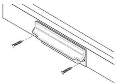
6
Slide the CanSweep® and low voltage wires into the opening on the baseboard. Friction fit the CanSweep®
natural_image
Technical line drawing of a mechanical bracket with screws, no text or symbols present4
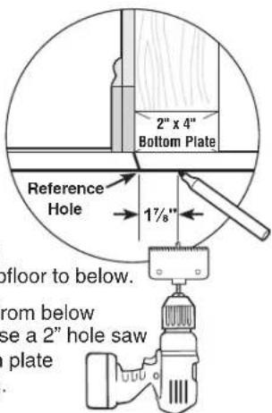
Drill a small reference hole at the mark through the subfloor to below.
Locate the reference hole from below and measure back 1 ^7/8 ". Use a 2" hole saw to remove the 2"x4" bottom plate section behind the opening.
WARNING
Do not install outdoors. Before hanging the unit, rest it on a leveled surface to prevent it from falling down. When performing installation, servicing or cleaning the unit, it is recommended to wear safety glasses and gloves.
LOCATING THE POWER UNIT
- Locate the power unit away from the general living area in an accessible location for cleaning and maintenance.
- Locate the power unit within 6 feet of a grounded electrical outlet. The power unit requires a 120 VAC power source, dedicated 15-amp branch circuit.
- Do not locate the power unit close to a source of extreme heat (i.e.: water heater) or in an area with a high ambient temperature (i.e.: attic, furnace room).
- If the power unit is located in a closet or a small utility room, make sure the area is well-ventilated (e.g.: with door louvers).
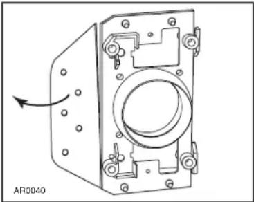
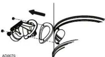
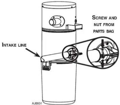
CHANGING INTAKE LINE DIRECTION
The intake line connects to the right side of the unit. However, it is possible to change this configuration; to connect the intake line to the left side of the unit, follow these steps:
① Remove debris pail from power unit by releasing both latches on sides of the unit, pulling them out and then pushing up. Detach the pail from unit.
BQ550
and
BQ500KIT: Grasp the edges of the bag collar and pull down; the bag will slide off easily. Do not pull on the bag. Set the bag aside.
BQ550 AND BQ500KIT
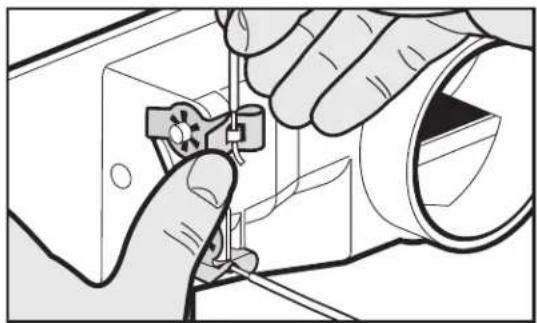
② BQ550 and BQ500KIT: Using a Phillips screwdriver no. 2, remove the screw tightening the bag adapter and intake elbow junction. Disassemble the bag adapter from the
side with its screw and nut.
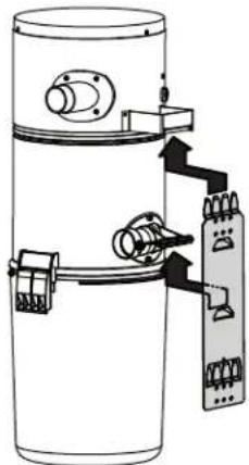
③ All units: Disassemble the intake elbow from the back of the unit using a 3/8" socket to remove both retaining nuts and screws.
natural_image
Mechanical assembly diagram showing a linkage mechanism with no visible text or symbols④ All units: Flip the intake elbow 180°, then reassemble it to the unit, taking care to keep its gasket at its original position.
NOTE: Ensure the gasket is not folded in
order to prevent lack of suction and noise.
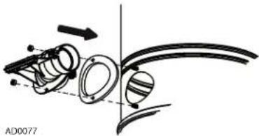
natural_image
Diagram of mechanical components with arrows indicating motion, no readable text or symbols present⑤ BQ550 and BQ500KIT:
Reassemble the bag adapter to the intake elbow. Align triangle with small inclined stud, then tighten the junction using the screw and nut previously removed in ②.
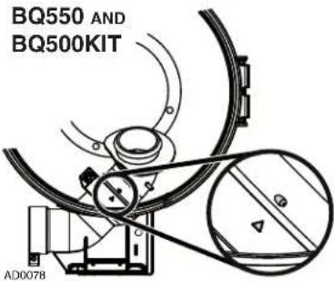
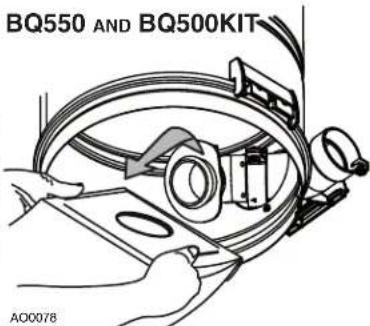
⑥ BQ550 and BQ500KIT:
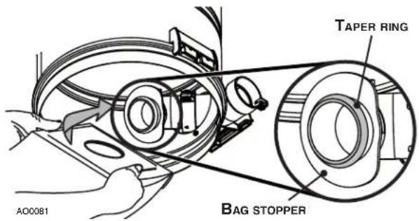
Put the bag back in place by grasping the edges of its collar and insert over bag adapter. Be careful not to tear the bag. Ensure the collar is positioned between the taper ring and the bag stopper on the bag
⑦ All units: Put the pail back in its place.
POWER UNIT INSTALLATION (CONT'D)
MOUNTING THE POWER UNIT
① Carefully remove debris pail from power unit. Make sure the bag is properly installed in power unit (BQ550 and BQ500KIT units). Remove the installation kit and securely reinstall debris pail.
② Refer to illustration below to maintain minimum walls and floor clearance dimensions.
MINIMUM CLEARANCE DIMENSIONS
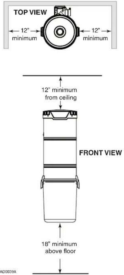
③ Position and install the wall mounting bracket with the provided screws. Refer to illustration in the right column for proper mounting dimensions.
CAUTION
Make sure to screw the wall mounting bracket directly to a wall stud for a solid installation.
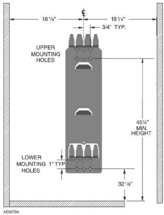
④ Use the provided mounting screws to secure the mounting bracket on the wall through upper and lower mounting holes.
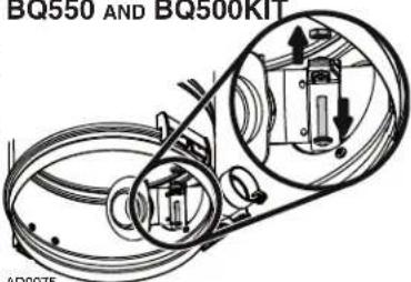
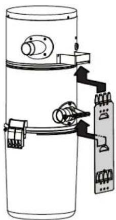
⑤ Hang power unit onto wall mounting bracket. Ensure the back brackets of the power unit are engaged with corresponding wall bracket fingers (or top fingers and lower tab for BQ550 and BQ500KIT models; see figure below). Pull the power unit down to secure.
BQ650 AND BQ700
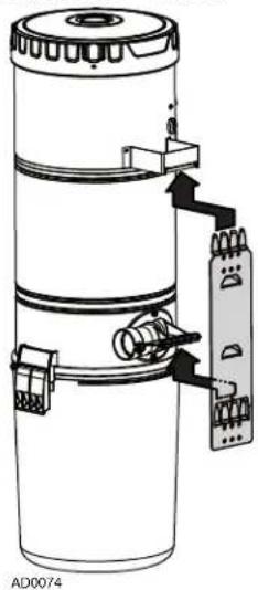
BQ550 AND BQ500KIT
natural_image
Diagram of a cylindrical device with internal components and wiring, showing no text or symbolsPOWER UNIT INSTALLATION (CONT'D)
FITTING MAIN LINE TO POWER UNIT
① Run house vacuum line up to the elbow behind the power unit. Insert the end of the line in the elbow opening and secure house vacuum line by hand tightening the screw and nut provided (see illustration below) DO NOT GLUE.
INTAKE LINE TYPICAL CONNECTION TO POWER UNIT
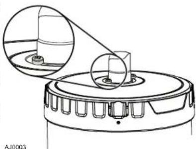
② Assemble exhaust tubing to exhaust outlet on top or top side of the unit, according to the power unit model. DO NOT GLUE.
NOTE FOR BQ700 UNIT ONLY
If desired, the coupling or elbow used to connect the exhaust line to the top of the unit may be secured using two 5/8" included screws. See illustration at right.
natural_image
Technical line drawing of a mechanical component with two circular insets showing internal components (no text or symbols)③ Make sure all tubing connections are air tight.
④ The exhaust should not be vented into a wall, ceiling or concealed space in the house. It is recommended to vent the vacuum exhaust air to the outdoors. Exterior vented exhaust line should end using Model V145 wall cap.
NOTE: For optimal indoor air quality, exhausting the power unit to the outdoors is recommended but is not required.
GROUNDING INSTRUCTIONS
WARNING
Improper connection of the equipment-grounding conductor can result in a risk of electric shock. Check with a qualified electrician or service person if you are in doubt as to whether the outlet is properly grounded. Do not modify the plug provided with the appliance – if it will not fit the outlet, have a proper outlet installed by a qualified electrician.
Grounding Instructions – This appliance must be grounded. If it should malfunction or break down, grounding provides a path of least resistance for electric current, to reduce the risk of electric shock. This appliance is equipped with a cord having an equipment-grounding conductor and grounding plug. The plug must be plugged into an appropriate outlet that is properly installed and grounded in accordance with all local codes and ordinances.
WIRING
This appliance is for use on a standard 120 VAC, dedicated 15-amp branch circuit with a NEMA 5-15R receptacle. Make sure that the power unit is connected to an outlet and has a grounding attachment plug that looks like the plug shown in illustration below. No adapter should be used with this power unit.
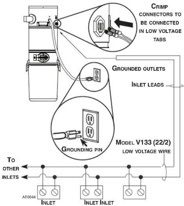
NOTE: Inlet leads to be connected to power unit low voltage tabs using crimp connectors (included in parts bag) and low voltage harness.
Open the wall inlet cover and insert the end of the hose into the inlet to turn on the vacuum.
For non-switched hoses, inserting the hose automatically turns on the power unit; removing the hose shuts off the power unit. Some hoses have switches which can be used to activate power unit. The ON/OFF switch located on the power unit needs to be kept in the OFF position.
As you vacuum, dirt and dust are carried to the power unit where they remain in a bag or in the debris pail (according to the power unit model).
Use the cleaning tools as you would for any other vacuum cleaner. Avoid picking up very large debris or lengthy as these kinds of objects may become lodged in the hose or tubing.
WHEN TO CHANGE BAG\* OR EMPTY DEBRIS PAIL
With a 6 U.S. gallons (22.7 liters) capacity, under normal conditions the bag/debris pail requires changing/emptying approximately twice a year. If the bag/debris pail is full, you will notice a reduced suction from the system. Unless this loss of suction is caused by a blockage in the system, changing the bag or emptying the debris pail will solve the problem.
NOTE: Even if not filled to capacity, if the bag seems tightly stretched when removing the debris pail, changing the bag will prevent it from tearing.
* Only BQ550 and BQ500KIT units are equipped with a disposable bag (391C).
HOW TO EMPTY DEBRIS PAIL (BQ650 AND BQ700 POWER UNITS ONLY)
To empty the debris pail, release both latches on sides of the unit by pulling out and then pushing up. Holding the pail by the latches, lower it from unit. Carry pail to trash receptacle and dispose of debris. Put the pail back in its place.
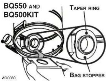
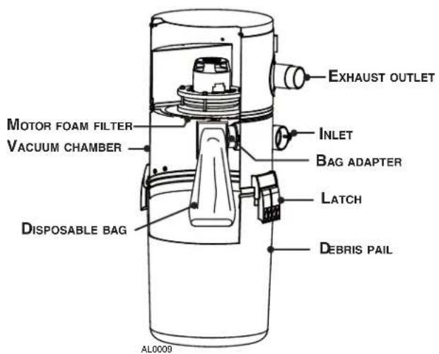
BQ550 AND BQ500KIT POWER UNITS DETAILED VIEW
DISPOSABLE BAG REPLACEMENT (BQ550 AND BQ500KIT POWER UNITS ONLY)
To remove the disposable bag, release both latches on sides of the unit by pulling out and then pushing up. Remove the pail from unit. Grasp the edges of the bag collar and pull down. The bag will slide off easily. Do not pull on the bag.
② Unfold the new bag.
③ Grasp collar where indicated on the new bag and insert over bag adapter. Be careful not to tear the bag. Ensure the collar is positioned between the taper ring and the bag stopper on the bag adapter (see illustration below). Put the pail back in its place.
This filter protects the motor and stops small particles from escaping to the outside of the power unit without the need to replace it. The filter cleans itself by moving up when the power unit starts, and dropping down when the unit is turned off. Under normal use, there is no need to maintenance this filter. It is possible to remove it to inspect the motor foam filter, or to replace it if ever it has been damaged (by sharp debris, for example).
REMOVAL AND INSTALLATION OF PERMANENT FILTER (BQ650 AND BQ700 POWER UNITS ONLY)
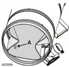
Remove the pail from unit. To remove the permanent filter, use pull tab (A) located on edge of filter to pull and loosen filter from inlet chamber wall. Squeeze from both sides of
the filter to the center of the housing. Then, carefully remove it from the unit.
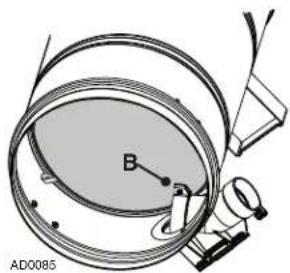
② Squeeze the filter in order to move it past the inlet opening (B) Let the filter bear against the unit wall by releasing the pressure.
Make sure to place the rigid ring in its groove to ensure proper sealing.
NOTE: Make sure the filter is installed so that the pull tab (A) is accessible for future filter removal.
natural_image
Technical diagram of a mechanical assembly with labeled components (no readable text or symbols)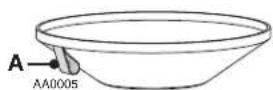
CAUTION
Be sure to reinstall filter properly. Appropriate location is critical to insure proper protection of the motor.
MOTOR FOAM FILTER (ALL UNITS)
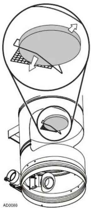
A motor foam safety filter, located at the top of the vacuum chamber provides protection against dirt being pulled into the motor if the disposable bag or permanent filter should accidentally be torn. This filter should be checked and cleaned if necessary when replacement bag is installed (BQ550 and BQ500KIT units only), or when permanent filter is removed (BQ650 and BQ700 units only). Simply brush filter clean. If the filter is excessively soiled, hand wash in a water and mild detergent solution and let it dry completely on a flat surface before reinstalling.
CAUTION
Operating the power unit without the motor foam filter will void the warranty.
REMOVING MOTOR FOAM FILTER
Remove the debris pail and disposable bag or permanent filter. Lift the center of the wire retaining the motor foam filter and slide the filter out of its location.
REINSTALLING MOTOR FOAM FILTER
To reinstall the motor foam filter, reverse the steps described above.
natural_image
Technical diagram of a mechanical device with internal components and directional arrows (no text or symbols)ACCESSORIES (BQ500KIT ONLY)
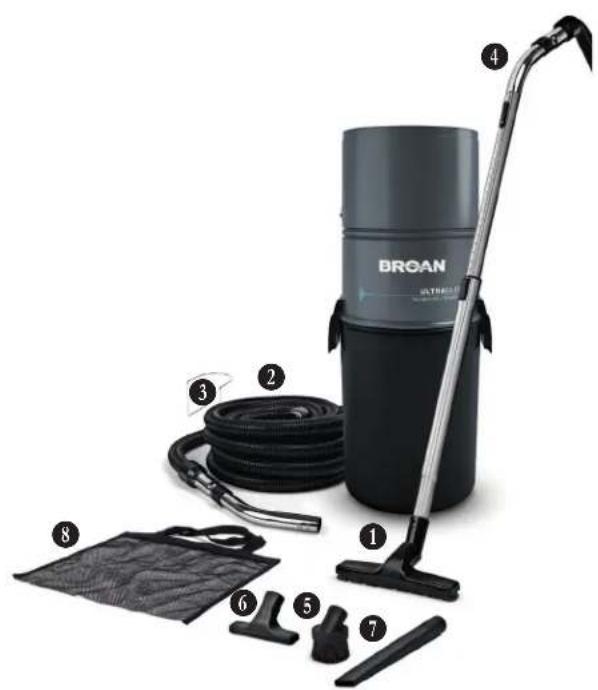
ACCESSORIES INCLUDED
① Standard floor brush
② Standard hose, 30 ft. long
③ Hose hanger
④ Telescopic wand for static tools
5 Round dusting brush
⑥ Upholstery tool
⑦ Long crevice tool
8 Storage bag
natural_image
Product photo of a BRGAN vacuum cleaner with attached hoses and accessories (no text or symbols visible)AA0056
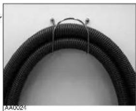
INSTALLING HOSE HANGER
① Secure the hose hanger to the wall using 2 provided screws. According to the place chosen, the use of wall anchors (not included) may be necessary.
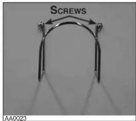
② Wind hose around its hanger when not in use.
natural_image
Close-up of a black corrugated cable with metal wire, no visible text or symbols| PROBLEMS | POSSIBLE CAUSES | POSSIBLE REMEDY |
| 1. Loss or decrease of suction occurs. | Debris pail or disposable bag is completely full.Debris pail gasket damaged or missing.Obstruction in the hose. A blockage in the hose can be determined by inserting the hose into any wall inlet and, while power unit is running, check each additional inlet for normal suction by holding the palm of your hand over the open inlet. If normal suction is felt at all other inlets, insert the hose into a second inlet. If the blockage still exists it is located in the hose. However, if the blockage does not occur when the hose is changed, the blockage is probably located in the tubing system leading to the original inlet.Obstruction in the tubing system inside the walls.Permanent filter or disposable bag torn.Wall inlet cover not properly sealed.Exhaust tubing or vent clogged. | Change the disposable bag or empty debris pail as described on page 10.Replace the debris pail gasket.Disconnect the hose from the wall inlet and insert a blunt instrument into the hose — slightly smaller in diameter — such as a flexible garden hose. Push the garden hose through the cleaning system hose until the obstruction has been cleared.Insert hose end into any inlet to make power unit run, then place the palm of your hand over the opposite end of the hose. When you can feel the suction increase, hold your hand over the hose end for a few seconds and then quickly remove your hand. This procedure repeated several times should clear the obstruction. If the blockage is not cleared, contact your nearest Service Center.Clean the interior or the unit and install a new permanent filter (or disposable bag).Check all wall inlet covers to be sure they are closed and sealed tightly.Inspect and remove any blockages. |
| 2. Power unit does not start, or stops suddenly. | Defective inlet. Check other wall inlets.Power unit internal circuit breaker has been activated (the reset button is popped up).Blown fuse or tripped circuit breaker on house electrical panel.Defective hose.Power unit overcurrent protector has been activated. | Replace defective wall inlet.Push on the circuit breaker reset button located on the left side of the power unit. If this button pops up again, contact your authorized Service Center.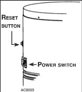 Replace fuse or reset circuit breaker on house electrical panel. Ensure the circuit is DEDICATED to the central vacuum unit, meaning that there is no other electrical device connected to the central vacuum unit circuit.Some brands of house panel breakers may be more sensitive to startup current than others (for example, Square D brand). Correct the situation by changing the breaker with an “HM” type of the same AMP rating.Replace hose as required.Unplug the power unit, wait at least 15 minutes and plug the power unit back in. Replace fuse or reset circuit breaker on house electrical panel. Ensure the circuit is DEDICATED to the central vacuum unit, meaning that there is no other electrical device connected to the central vacuum unit circuit.Some brands of house panel breakers may be more sensitive to startup current than others (for example, Square D brand). Correct the situation by changing the breaker with an “HM” type of the same AMP rating.Replace hose as required.Unplug the power unit, wait at least 15 minutes and plug the power unit back in. |
| 3. Power unit runs continuously when the hose is removed. | The unit power switch is in ON position.An electrical short has occurred somewhere in the system. | Set the unit power switch to OFF position.Perform a complete check of all wall inlets and power unit low voltage control lead connections. Contact your authorized Service Center. |
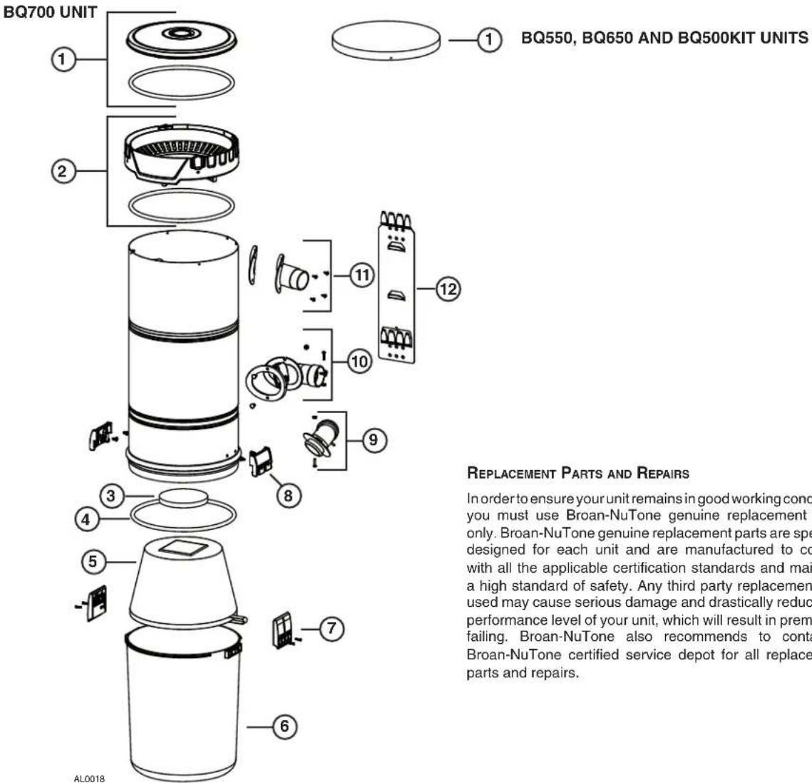
| KEY NO. | PART NO. | DESCRIPTION | BQ500KIT | BQ550 | BQ650 | BQ700 |
| 1 | S10941409 | BQ700 TOP CAP ASSEMBLY (INCLUDING ITEM 4) (UPPER PART) | 1 | |||
| S10941417 | BQ550, BQ650 AND BQ500KIT TOP CAP ASSEMBLY | 1 | 1 | 1 | ||
| 2 | S10941398 | BQ700 TOP CAP ASSEMBLY (INCLUDING ITEM 4) (LOWER PART) | 1 | |||
| 3 | 66369 | MOTOR FOAM FILTER WITH FASTENER | 1 | 1 | 1 | 1 |
| 4 | S10941400 | GASKET | 1 | 1 | 1 | 3 |
| 5 | S10941401 | PERMANENT FILTER | 1 | 1 | ||
| 6 | S99670648 | DEBRIS PAIL (INCLUDING KEY NO. 7) | 1 | 1 | 1 | 1 |
| 7 | S10941199 | LATCH AND SCREWS | 2 | 2 | 2 | 2 |
| 8 | S10941404 | LATCH KEEPER WITH SCREWS | 2 | 2 | 2 | 2 |
| 9 | S10941405 | BAG ADAPTER WITH NUT AND SCREW | 1 | 1 | ||
| 10 | S10941406 | INTAKE ELBOW WITH GASKET, SCREWS, AND NUTS | 1 | 1 | 1 | 1 |
| 11 | S99670650 | EXHAUST PORT WITH GASKET AND SCREWS | 1 | 1 | 1 | |
| 12 | S30390555 | UNIT SUPPORT BRACKET | 1 | 1 | 1 | 1 |
| * | 391C | DISPOSABLE BAG (SET OF 3) | 1 | 1 |
* ITEM NOT SHOWN
NOTE: Order service parts by "Part No." — not by "Key No."
BROAN MODELS BQ550, BQ650, BQ700 AND BQ500KIT
VENMAR VENTILATION ULC
CENTRAL VACUUM POWER UNIT LIMITED WARRANTY
Venmar Ventilation ULC warrants to the original consumer purchaser that its central vacuum power unit will be free from defects in materials and workmanship for five (5) years for BQ550 and BQ500KIT units, eight (8) years for BQ650 units and ten (10) years for BQ700 units. This warranty covers the parts and labor in an authorized service center for the first year of the warranty for BQ500KIT units, the first three (3) years of the warranty for BQ550 units, the first five (5) years of the warranty for BQ650 units, the first six (6) years of the warranty for BQ700 units. After these time periods, the parts only will be covered under this warranty.THERE ARE NO OTHER WARRANTIES, EXPRESSED OR IMPLIED, INCLUDING, BUT NOT LIMITED TO, IMPLIED WARRANTIES OF MERCHANTABILITY OR FITNESS FOR A PARTICULAR PURPOSE.
During these time periods, Venmar Ventilation ULC will, at its option, repair or replace the power unit or part without charge, which is found to be defective under normal use and service. THIS WARRANTY DOES NOT APPLY TO THE INSTALLATION OR THE PARTS USED IN THE INSTALLED TUBING SYSTEM. All central vacuum hoses, electric or air-driven brushes, filters, attachments and accessories are warranted for one (1) year from the original purchase date with the exception to consumables such as light bulbs and belts. We invite you to register your product on line at www.broan.ca. Venmar Ventilation ULC reserves the right to limit this warranty if the product is not registered.
This warranty does not cover (a) normal maintenance and service or (b) any products or parts which have been subject to misuse, negligence, accident, improper maintenance or repair (other than by Venmar Ventilation ULC or an authorized representative), faulty installation or installation contrary to recommended installation instructions.
The duration of any implied warranty is limited to the period as specified for the express warranty.
VENMAR VENTILATION ULC'S OBLIGATION TO REPAIR OR REPLACE, AT VENMAR VENTILATION ULC'S OPTION, SHALL BE THE PURCHASER'S SOLE AND EXCLUSIVE REMEDY UNDER THIS WARRANTY. VENMAR VENTILATION ULC SHALL NOT BE LIABLE FOR INCIDENTAL, CONSEQUENTIAL OR SPECIAL DAMAGES ARISING OUT OF OR IN CONNECTION WITH PRODUCT USE OR PERFORMANCE. Please do not return your unit to place of purchase. Please visit www.broan.ca for your closest service center. You may also call 1-877-896-1119 for the name of an authorized representative in your area. This warranty supersedes all prior warranties.
Warranty service is to be completed by an authorized Service Center designated by Venmar Ventilation ULC. Where applicable, in home service will be made available only in areas where a contracted service provider offers service during the first year of the warranty for BQ500KIT units, during the first three (3) years of the warranty for the BQ550 units, during the first five (5) years of the warranty for the BQ650 units and during the first six (6) years of the warranty for the BQ700 units. If in home service is not available, the product will be repaired or replaced, at Venmar Ventilation ULC's discretion, by the nearest authorized service provider. The unit removal and reinstallation works are under the customer responsibility, and Venmar Ventilation ULC cannot be charged for them.
To qualify for warranty service, you must notify Venmar Ventilation ULC at the address or telephone number stated below. We will then forward you the authorized service depot in your area. You will be required to present evidence of the original purchase date.
Date of Installation Builder or Installer
Model Number and Product Description
IF YOU NEED ASSISTANCE OR SERVICE
For the location of your nearest Venmar Ventilation ULC dealer, dial toll free: 1-877-896-1119
Please be prepared to provide: Product model number • Date and proof of purchase • The nature of the difficulty
Venmar Ventilation ULC
Product specifications subject to change without notice. Printed in Canada.
UNITÉS MOTRICES D'ASPIRATEUR CENTRAL
⚠️ POUR USAGE RÉSIDENTIEL SEULEMENT ⚠️
BQ550 / BQ650 / BQ700 / BQ500KIT
natural_image
Line drawing of a cylindrical container with two side handles and a handle, labeled AB0039 (no text or symbols on the diagram itself)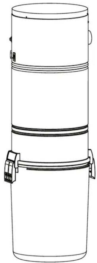
natural_image
Line drawing of a cylindrical container with two side handles and a top lid (no text or symbols)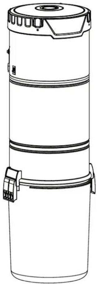
natural_image
Line drawing of a cylindrical industrial device with a lid and two attached clamps (no text or symbols)MODÈLES SFDB-DH, SFDB-DI, SFDB-DJ ET SFDB-DT
VENMAR VENTILATION ULC WWW.BROAN.CA 1 877-896-1119
natural_image
Illustration of two hand positions: top shows hands using a tool on a table, bottom shows hands holding a cup (no text or symbols)COLLAGE DU TUYAU FLEXIBLE
natural_image
Illustration of a medical procedure with hands and instruments (no text or symbols visible)INSTALLATION D'UNE PRISE MURALE
DÉCOUPE DE LA PRISE MURALE
natural_image
Technical line drawing of a mechanical housing component with mounting holes and a circular component (no text or symbols)natural_image
Line drawing of a person holding a camera (no text or symbols)INSTALLATION SOUS UNE ARMOIRE V800W CANSWEEP ^D
natural_image
Illustration of a hand using a power tool to draw or install a rectangular block (no text or symbols present)4
natural_image
Illustration of hands using a tool to cut or install a mechanical component, labeled 'Fig. B' (no text on diagram)natural_image
Diagram of a hand holding a tool interacting with a mechanical component (no text or symbols visible)7
natural_image
Illustration of hands assembling or adjusting a mechanical component (no text or symbols visible)3
natural_image
Technical line drawing of a mechanical bracket with screws inserted, no text or symbols presentnatural_image
Diagram of a mechanical assembly with rotating components and directional arrows (no text or symbols)natural_image
Technical line drawing of a mechanical component with arrows indicating motion (no text or symbols)natural_image
Technical diagram of a cylindrical device with attached electrical connectors and a connector block (no text or symbols)BQ550 ET BQ500KIT
natural_image
Diagram of a cylindrical device with internal components and a separate electrical connector (no text or symbols)INSTALLATION DE L'UNITÉ MOTRICE (SUITE)
RACCORD DE LA LIGNE PRINCIPALE À L'UNITÉ MOTRICE
natural_image
Technical diagram of a mechanical assembly with labeled component B, no readable text or symbols present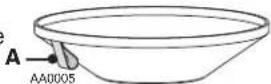
accessible
pour
ATTENTION
natural_image
Technical diagram of a mechanical assembly with labeled components and directional arrows (no readable text or symbols)un
ACCESSOIRES (BQ500KIT SEULEMENT)
ACCESSOIRES INCLUS
natural_image
Product photo of a BRCAN vacuum cleaner with attached hoses and accessories (no text or symbols visible)AA0056