
AC1143 - Memory reader IFM - Free user manual and instructions
Find the device manual for free AC1143 IFM in PDF.
| Product type | AS-i addressing and maintenance unit / Memory reader |
| Brand | IFM |
| Model | AC1143 |
| Category | Memory reader |
| Display | LCD 2 lines, 8 characters |
| Keyboard | 5 setting keys (Function, Increment, Decrement, Write/Confirm, Read/On) |
| Power supply | Integrated rechargeable battery, external charger 6V DC (E70222 included) |
| External power supply | Jack connector, charger 230V/6VDC supplied |
| Interfaces | M12 female 5-pin connector for addressing, Sub-D9 male connector for maintenance, Jack connector for power supply, Memory card slot (E70221) |
| Main functions | Read/write AS-i address, I/O configuration, ID code; backup/restore Ecolog projects (AS-i program and configuration) between PC, controller and memory card; format memory card |
| Memory card capacity | Not specified (automatic formatting when inserting a new card) |
| Maintenance and cleaning | Clean with a soft, dry cloth. Do not use liquids. |
| Safety | Do not connect to the existing AS-i cable; use only the supplied 6V charger; discharged battery displays "Low-Batt" |
| Included accessories | Charger 230V/6VDC (E70222) |
| Compatible software | Ecolog AS-i System |
| General information | Portable device for addressing and maintenance of AS-i networks |
Frequently Asked Questions - AC1143 IFM
User questions about AC1143 IFM
0 question about this device. Answer the ones you know or ask your own.
Ask a new question about this device
Download the instructions for your Memory reader in PDF format for free! Find your manual AC1143 - IFM and take your electronic device back in hand. On this page are published all the documents necessary for the use of your device. AC1143 by IFM.
USER MANUAL AC1143 IFM
... 3 Sekunden ...

... 3 Sekunden ...

... 3 Sekunden ...
... 3 Sekunden ...

... 3 Sekunden ...
... 3 Sekunden ...

- Fehlermeldungen
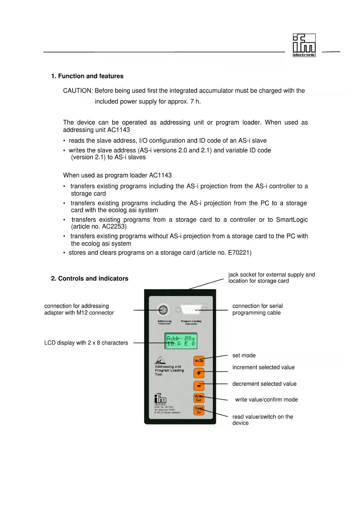
1. Function and features
CAUTION: Before being used first the integrated accumulator must be charged with the included power supply for approx. 7 h.
The device can be operated as addressing unit or program loader. When used as addressing unit AC1143
- reads the slave address, I/O configuration and ID code of an AS-i slave
- writes the slave address (AS-i versions 2.0 and 2.1) and variable ID code (version 2.1) to AS-i slaves
When used as program loader AC1143
- transfers existing programs including the AS-i projection from the AS-i controller to a storage card
- transfers existing programs including the AS-i projection from the PC to a storage card with the ecolog asi system
• transfers existing programs from a storage card to a controller or to SmartLogic (article no. AC2253)
• transfers existing programs without AS-i projection from a storage card to the PC with the ecolog asi system -
stores and clears programs on a storage card (article no. E70221)
-
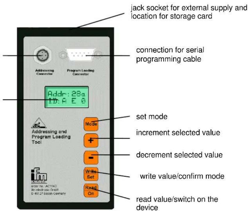
Controls and indicators
connection for addressing adapter with M12 connector
LCD display with 2 x 8 characters
3. Using the keypad
| Key Function | |
| Selection of the addressing or program loading / storage function Changeover between the different modes | |
| <+> | Increment slave address/extended ID code 1 |
| <-> | Decrement slave address/extended ID code 1 |
| Write slave address/extended ID code 1 / confirm mode | |
| Read out slave address/extended ID code 1 / switch on the device. To do so, press the key for approx. 0.5 s. | |
4. Connections
| Connection Description | |
| Addressing connector | 5-pole M12 connection socket for the addressing cablee.g. addressing cable for the mechanical addressing interface E70213addressing adapter for compact modules E70123IR addressing adapter E70211 |
| Program loading connector | 9-pole SUB-D plug for the connection to the controller or PCwith a null modem cable (e.g. AC4010) or to SmartLogic with theaddressing cable E70239 |
| Jack socket for the connection of an external supply voltage(upper front face) | |
| Location for the storage card (upper front face) | |
Note: The designations of the different keys are indicated with the key name in pointed brackets and bold print.
Example:
The displays and the different functions are indicated in inverted commas and bold print.
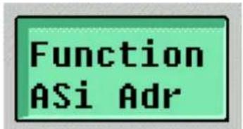
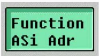
Example: " Function ASi Adr"
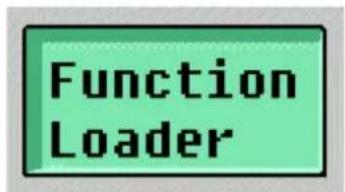
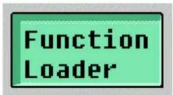
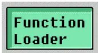
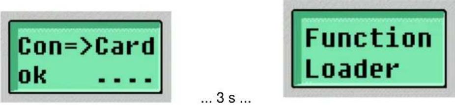
5. Selection of the operating modes "addressing unit" or "program loader"
After power on with
In the first line of the display the menu name "Function" and the selection option as addressing unit "ASi Adr" are then indicated.
With the

Pressing the
5.1 The operating mode "addressing unit"
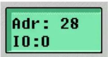
After selection of the operating mode "addressing unit" the address, the I/O code and the ID code of the slave are read and indicated with the slave being connected.
By pressing
After connection of a slave the address, the I/O code and the ID code of the slave can be read by pressing
The addressing unit must not be connected to an existing AS-i network since the AS-i voltage required for programming is generated by the addressing unit itself. If a slave with a mechanical addressing socket is used, the addressing plug is inserted to separate from the AS-interface.
The I/O code is indicated as follows:
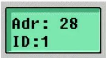
After approx. two seconds the ID code is shown.
If the connected slave is a slave of the version 2.0, the address is indicated with one or two digits and the ID code with one digit.
If the connected slave is a slave of the version 2.1 with extended addressing mode, the address and whether it is an A or B slave are indicated. Beside the ID code the "extended ID code 1" and the extended ID code 2 are shown.
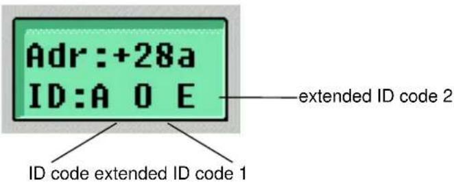
During the manufacturing process the ID code and the extended ID code 2 are permanently stored in the slave and can only be read out. However, the "extended ID code 1" can be changed.
In the display the read or set address flashes. By pressing <+> or <-> the address can be incremented or decremented. By a prolonged pressing of <+> or <-> the address is automatically counted up or down. If as ID code "A" has been read (extended addressing mode), the address can be set as follows: 0, 1a, 1b, 2a, 2b, ..., 31a, 31b.
By pressing
With the
If no slave is detected, "No Slave" is shown for approx. 2 s and then you automatically pass to the state "Function ASi Adr".

2 s
5.2 The operating mode "program loader"
In this operating mode of the addressing and program loading unit a program and the corresponding AS-i projection of a project can be stored from an AS-i controller or a PC on a storage card (article no. E70221) or the program can be transferred from a storage card to an AS-i controller or SmartLogic. To do so, the software "ecolog asi system" and a null modem cable (article no. AC4010) are required.
Programs on storage cards which have already been used can be cleared in this operating mode. Thus the storage cards can be reused.
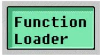
After selection of the operating mode "Loader" the device first checks whether a storage card has been inserted. If no storage card is inserted, the message "No Card" appears.

If a storage card has been inserted when selecting the function "Loader" and pressing
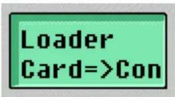
With the
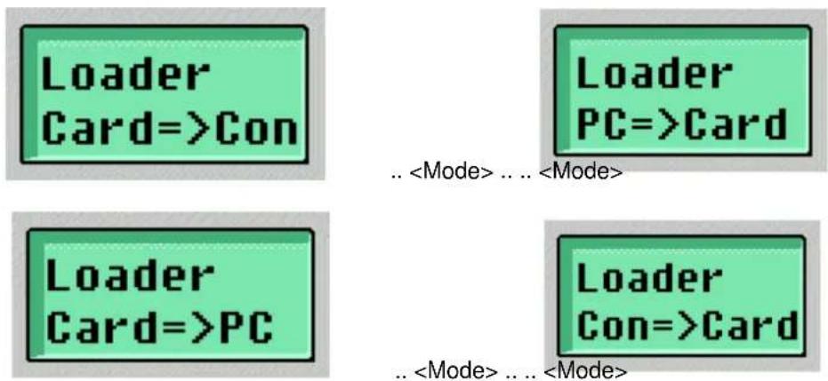
With the
5.2.1 Project transfer from a PC to the storage card
With this function a PLC program including AS-i projection is stored from the PC on the card using the software ecolog asi system. To do so, the serial PC interface (COM1 or COM2) must be connected to the interface "Program loading connector" of the addressing and program loading unit with a null modem cable.
To be able to transfer a program from the software ecolog asi system the user must first log into the addressing and program loading unit via the menu point "Online/Login" after selection of the loader function "PC=>Card" and pressing
"The projections in PLC and PC are different! Which projection should be taken?"
with
"Download to PLC"
In this case the program loading unit serves as a "PLC". The program is then loaded on the card, i.e. the question
"No program on the controller! Download the new program?"
must be confirmed with
"Ja" (yes)
After loading the AS-i projection and the PLC program the communication with asisys is interrupted.
If the question
"No program on the controller! Download the new program?"
is confirmed with
"Nein" (no)
the eASi tool remains logged in. In the configuration window (selection via the menu point "Window/PLC Configuration") the submenu "Bin. Download" is then available under the menu point "Extras" to transfer a program from the hard disk or a diskette to the storage card.
If the loader function "PC=>Card" has been selected and confirmed by pressing
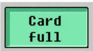
If it is not empty, the message "Card full" is indicated for approx. 3 s and then the loader function "Clear" (see section 5.2.4) is activated. If it is necessary, the inserted storage card can be cleared.

... 3 s ...

If the storage card is empty, "PC=> Card Wait.." is displayed.
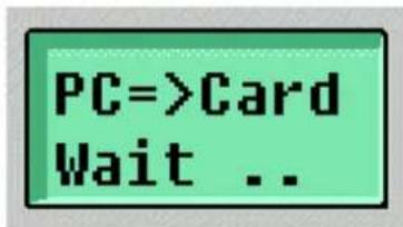
The loader is now ready for downloading the PLC program and the related AS-i projection to the addressing and program loading unit.
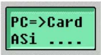
After starting download in the ecolog asi system (after "Login" or after selection of the configuration window, menu point "Extras/Bin. Download") the display changes over to "PC=> Card ASi ...." as long as the related AS-i projection is being transferred.
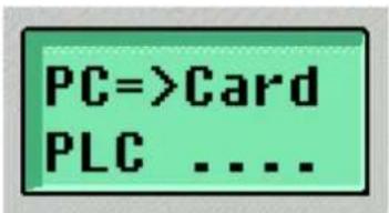
After the transfer of the AS-i projection the program is transferred from the PC to the storage card. This is indicated with the message "PC=> Card PLC ...." as long as the program is being transferred.
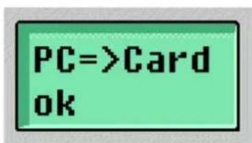
After a successful download "PC=>Card ok ..." is displayed for approx. 3 s. Then the selection of the loader function is activated again.
It is not possible to transfer only the projection since the actual transfer of the projection does not start before the program transfer.

... 3 s ...
By pressing
5.2.2 Project transfer from the storage card to the PC
With this function a PLC program including AS-i projection is loaded from the storage card to the PC and then stored using the software ecolog asi system. To do so, the serial interface of the PC (COM1 or COM2) must be connected to the interface "Program loading connector" of the addressing and program loading unit with a null modem cable.
To transfer a program from the storage card to the software ecolog asi system, the user must first log into the addressing and programming loading unit via the menu point "Online/Login" after selection of the loader function "Card=>PC" and pressing
To do so, a "dummy program" must be created because otherwise logging into the controller is rejected with the message
"The project must be correct for login"
In the window "Messages" the following message is indicated:
"Error: Project must contain a POU named PLC\_PRG (main routine)"
To create the dummy program insert a POU type "program" named "PLC_PRG" via the menu point "Project/Add object". To ensure that this POU is accepted by the compiler of the ecolog asi system there must be at least one instruction. In IL this instruction can for example be "LD 0" or in FBD "TRUE".
After creation of the dummy program the user can connect to the program loading unit as usual via the menu point "Online/Login".
After login the projections are compared. To do so, the message
"The projections in PLC and PC are different! Which projection should be taken?"
must be confirmed with
"Download from PLC"
The following question
"No program on the controller! Download the new program?"
must be confirmed with
"Nein" (no)
to keep the program loading unit logged in. In the configuration window (selection via the menu point "Window/PLC configuration") the submenu "Bin Upload" is available under the menu point "Extras". The projection indicated in the ecolog asi system now corresponds to the current projection stored on the card.
If the loader function "Card=>PC" has been selected by pressing

... 3 s...
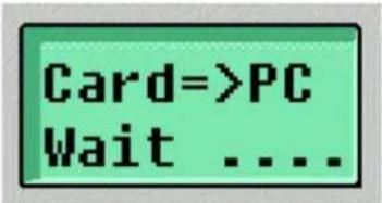
In the case of a loaded storage card "Card => PC Wait ...." is displayed.
The loader is now ready for uploading the PLC program and the related AS-i projection to the PC.
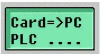
After starting upload in the ecolog asi system (after "Login", configuration window, menu point "Extras/Bin. Upload") a program name and a file path can be entered. The display then changes over to "Card=>PC PLC...." as long as the PLC program is being transferred.
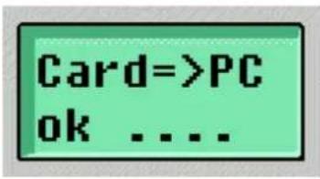
After a successful upload "Card=>PC ok ...." is displayed for about 3 s. Then the selection of the loader function is activated again and the connection to the program loading unit is interrupted.
... 3 s...
With the
5.2.3 Project transfer from the controller to the storage card
With this function a PLC program including AS-i projection is stored from the controller on the storage card in the program loading unit. To do so, the serial interface of the controller must be connected to the interface "Program loading connector" of the addressing and program loading unit with a null modem cable.
If the loader function "Con=>Card" has been selected by pressing
If it is not empty, the message "Card full" is indicated for approx. 3 s and then the loader function "Clear Card" (see section 5.2.4) is activated.
... 3 s ...

If the storage card is empty, the upload starts immediately.
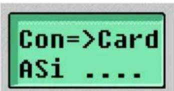
During the projection transfer the message "Con=>Card ASi ...." is displayed and then while the PLC program is being transferred "Con=>Card PLC ....".
...
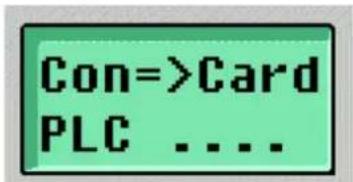
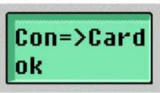
After a successful upload "Con=>Card ok ...." is displayed for approx. 3 s. Then the selection of the loader function is activated again.
By pressing
5.2.4 Project transfer from the storage card to a controller
With this function a PLC program including AS-i projection is loaded from a storage card in the program loading unit to a controller. To do so, the serial interface of the controller must be connected to the interface "Program loading connector" of the addressing and program loading unit with a null modem cable.
If the loader function "Card=>Con" has been selected by pressing

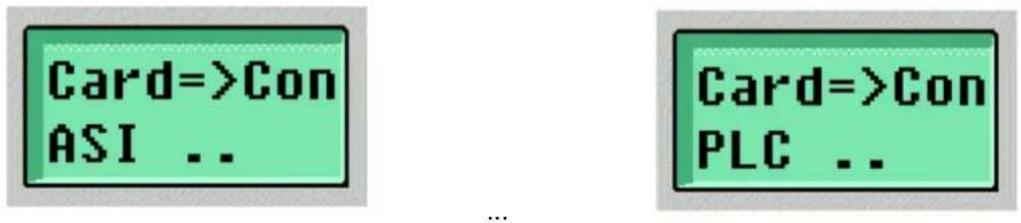
If the storage card contains a program, download starts immediately. During the transfer of the projection the message "Card=>Con ASi ..." is displayed and then "Card=>Con PLC ..." while the PLC program is being transferred.
After a successful download "Card=>Con ok ...." is displayed for approx. 3 s. Then the selection of the loader function is activated again.
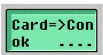
... 3 s ...
By pressing
Note: After the transfer of a program the controller remains in the Stop mode and must be set to the RUN mode either via the software ecolog asi system, menu point "Online/Start" (or by pressing
In order to set the controller to the RUN mode manually the controller keys
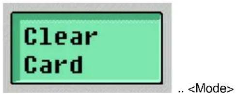
5.2.5 Clearing a storage card
With the function "Clear Card" the program on an inserted storage card is cleared.

After selection of the function "Clear Card" by pressing

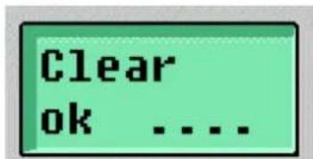
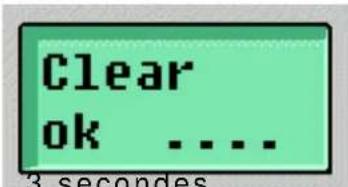
After clearing "Clear ok ...." is displayed for approx. 3 s. Then the selection of the loader function is activated again.
... 3 s ...

6. Formatting a storage card
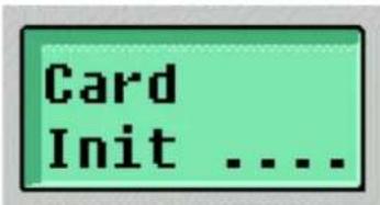
If a new storage card is inserted in the addressing and program loading unit, the device automatically formats and initialises the card. During initialisation the message "Card Init ...." is displayed.
- Error messages
| Display Meaning | |
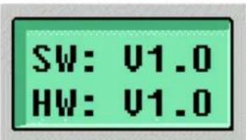
 | If the accumulator is below a certain voltage, this message is indicated until a key is pressed after power on and display of the SW-HW version.In this case the accumulator should be connected to the included plug-in power supply and loaded. |
 | Error messages AS-i:10: Error during writing AS-i slave data11: Error during reading AS-i slave data12: AS-i protocol error, parity13: AS-i protocol error, end bit14: Reserved15: AS-i power fail16: AS-i infrared distance, protocol error17: AS-i infrared distance, no AS-i signal18: No reply from AS-i slave19: Error AS-i slave version |
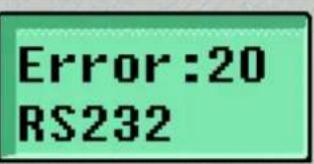 | Error messages serial interface20: Overflow of the serial reception buffer21: Protocol error (incorrect baud rate)22: Protocol error (parity)23: Protocol error (data contents)24: Protocol error (data length)25: Timeout serial interface26: Reserved27: Reserved28: Reserved29: Reserved |
 | Error messages storage card30: Error during access to card31: Error card identification32: Error during clearing the card33: Error during reset execution34: Error during writing35: Error during reading36: Error card initialisation37: Error checksum during reading38: Reserved39: Reserved |
8. Charging the accumulator
The accumulators of the eASi tool are charged via the jack socket for external supply. After connection of the power supply "Charge Batt" is displayed.
Charge Batt
During the charging time moving points in the display indicate that the device is in the state of being charged. During charging all functions of the device can be used by pressing the
Charge Batt ....
After 7 hours of charging "Charge Batt ok" is displayed. The accumulators are now charged and should not be connected again to the power supply before Low batt is shown.
Charge Batt ok
CAUTION: To charge the accumulators only the included power supply with a 6 V charging voltage may be used. Power supplies with higher voltage can damage the eASi tool.
9. Optional accessories
The following accessories can be obtained for the addressing and program loading unit:
| Article number | Description |
| E70123 Addressing adapter for addressing compact modules | |
| E70211 Infrared addressing adapter for addressing modules with IR addressing interface | |
| E70213 Addressing plug for addressing modules with mechanical addressing interface | |
| E70221 Storage card | |
| E70239 Serial connection cable SmartLogic (AC2253) – program loader | |
| AC4010 Serial connection cable (null modem) PC/controller – program loader | |

3 secondes puis
(configuration AS-i) (programme) (3 secondes)
(programme) (3 secondes)
(Configuration AS-i) (Programme) (3 secondes)
Sélectionner
et valider par
puis
- Function and features
- Using the keypad
- Connections
- Selection of the operating modes "addressing unit" or "program loader"
- The operating mode "addressing unit"
- The operating mode "program loader"
- Project transfer from a PC to the storage card
- "The projections in PLC and PC are different! Which projection should be taken?"
- "Download to PLC"
- "No program on the controller! Download the new program?"
- "Nein" (no)
- Project transfer from the storage card to the PC
- "The project must be correct for login"
- "Error: Project must contain a POU named PLC\_PRG (main routine)"
- "Download from PLC"
- Project transfer from the controller to the storage card
- Project transfer from the storage card to a controller
- Clearing a storage card
- Formatting a storage card
- Charging the accumulator
- Charge Batt
- Charge Batt ....
- Charge Batt ok
- Optional accessories
Brand : IFM
Model : AC1143
Category : Memory reader