
WX-SA250 - Microphone PANASONIC - Free user manual and instructions
Find the device manual for free WX-SA250 PANASONIC in PDF.
| Product type | Wireless antenna |
| Brand | Panasonic |
| Model | WX-SA250 |
| Frequency | 1.9 GHz (ISM band) |
| Compatible system | WX-SR200P |
| Usage | Digital wireless microphone system |
| Associated software | Easy Design Tool (WX-SR200P Series) |
| Installation methods | Ceiling, wall |
| Application | Meeting rooms, classrooms, conferences |
| Typical range (mid-field) | Approximately 49 ft (15 m) for secondary antenna, 131 ft (40 m) for main antenna |
| Power supply | Via the WX-SR200P system (PoE) |
| Maintenance and cleaning | Clean with a dry, soft cloth |
| Safety | Use in accordance with local radio frequency regulations |
| Spare parts | Contact an authorized Panasonic dealer |
| Repairability | Call a qualified technician |
| Operating conditions | Ambient temperature, indoor |
Frequently Asked Questions - WX-SA250 PANASONIC
User questions about WX-SA250 PANASONIC
0 question about this device. Answer the ones you know or ask your own.
Ask a new question about this device
Download the instructions for your Microphone in PDF format for free! Find your manual WX-SA250 - PANASONIC and take your electronic device back in hand. On this page are published all the documents necessary for the use of your device. WX-SA250 by PANASONIC.
USER MANUAL WX-SA250 PANASONIC
Operating Instructions
1.9 GHz Digital Wireless Microphone System Easy Design Tool
Function overview
Easy Design Tool (hereinafter referred to as "this software") is software for considering the installation design of the following devices in advance on a personal computer (hereinafter referred to as "PC").
Wireless antenna: WX-SA250P
Wireless microphone: WX-ST200P, WX-ST400P, WX-ST700P
Wireless Transmitter: WX-ST600P

- This software is a tool to analyze the number of microphones that can be used in Panasonic's 1.9 GHz digital wireless microphone systems. Use it as a guide to wireless microphone system installation after paying attention to the following points.
- The calculation used for analysis is the general propagation equation, and the assumption is that the ceiling height is up to 4 meters.
- The typical value for insertion loss is applied as the default value.
- To simplify analysis, this software does not consider factors such as the floors above and below as analysis is limited to only two dimensions.
- To simplify analysis, this software does not consider objects that shield radio waves as analysis is limited to only considering room sizes.
Final checks should be made at the installation location of the wireless microphone system.
About This Manual
- This manual describes how to operate Easy Design Tool for 1.9 GHz digital wireless microphone systems. For information on the functions of the equipment, refer to the operating instructions supplied with the products.
- The software version information and other screen images shown in this manual are display examples and may differ from the actual screens.
System requirements
This software can be used on a PC with the following system environment.
Operating system*1 English version of Microsoft Windows 11 Pro
English version of Microsoft Windows 10 Pro
English version of Microsoft Windows 8.1 Pro
CPU The PC must be equipped with a CPU recommended for use with the above operating systems and Microsoft .NET Framework.
Memory The PC must be equipped with the memory recommended for use with the above operating systems and Microsoft .NET Framework.
Hardware disk free space There must be 100 MB of free space to install this software.
Microsoft .NET Framework is required to use this software.
If it is not installed, additional free space to install Microsoft .NET Framework is required.
Screen Resolution of 1280x800 pixels or higher
*1 This software is designed using the default styles and font sizes of Microsoft Windows 11, Microsoft Windows 10, and Microsoft Windows 8.1. Be sufficiently careful when changing a style or font size.

- With regards to .NET Framework, operation in the following environments has been verified.
Windows 11: .NET Framework 4.8
Windows 10: .NET Framework 4.8
Windows 8.1: .NET Framework 4.8
Copyrights
Distributing, copying, disassembling, reverse compiling, and reverse engineering of the software provided with this product as well as exporting it in violation of export laws are expressly prohibited.
Registered trademarks and trademarks
- Adobe, the Adobe logo, Acrobat, PostScript, and the PostScript logo are trademarks of Adobe Systems Incorporated.
- Microsoft, Windows, Internet Explorer, ActiveX, and DirectX are registered trademarks or trademarks of Microsoft Corporation in the United States and/or other countries.
- Other names of companies and products contained in this manual are trademarks or registered trademarks of their respective owners.
Abbreviations
This manual uses the following abbreviations.
- "Microsoft Windows" is referred to as "Windows".
- "Wireless Antenna (WX-SA250P)" is referred to as "antenna".
- "Wireless Microphone (WX-ST200P/WX-ST400P/WX-ST700P)", and "Gooseneck Microphone (WM-KG645)" that is connected to "Wireless Transmitter (WX-ST600P)" are referred to as "microphone".
- "Personal computer" is referred to as "PC".
All information on separately-sold products contained in this manual is up-to-date as of Oct. 2022. Contact a retailer for the latest information.
Software capabilities
The following table describes the functions of this software.
| Item Description | Explanation page | ||
| Installation design | Microphone location/analysis | Input the microphones you wish to place. Analyze the number of microphones that can be used with the considered antenna location. | 26, 39 |
| Antenna location/analysis | Input the areas in which you wish to place antennas and then perform antenna location analysis. | 28 | |
| Print Print the results of consideration. 41 | |||
Terms
The following explains terms used in this manual.
WX-SR200P system
System that uses wireless antennas (WX-SA250P) for the antennas in the 1.9 GHz digital wireless microphone system.
Main reference antenna
Antenna that serves as the reference for wireless synchronization when performing operation by wireless synchronizing between multiple antennas in a WX-SR200P system.
Sub reference antenna
Antenna that wirelessly synchronizes with the main reference antenna and serves as the reference of the sub system when performing operation by wireless synchronizing between multiple antennas in a WX-SR200P system.
Standalone antenna
Antenna that is connected to a system to be operated alone or antenna that is connected to a system in which wireless synchronization with other antennas is not performed.
SR200 antenna
Antenna other than the main reference antenna and sub reference antenna in a WX-SR200P system.
Symbols
This manual uses the following symbols in explanations.


: Indicates a hint on use.
Introduction 2
Function overview 2
About This Manual 2
System requirements 2
Copyrights 3
Registered trademarks and trademarks 3
Abbreviations 3
Software capabilities 3
Terms 4
Symbols 4
Installing and uninstalling the software 7
How to install....7
How to uninstall 7
Starting and exiting the software 8
How to start 8
How to exit....8
Easy wireless design operation flow 9
STEP1: Mapping 9
STEP2: Microphone location 11
STEP3: Antenna location 12
STEP4: Microphone analysis 13
Mapping 14
Loading a map (when map available) 14
Loading a map (when map not available) 16
Loading a map (loading a saved file) 17
Area input 18
Adding input areas 19
Changing and correcting input areas 20
Setting the scale 23
Area input completion 25
Microphone location 26
Antenna location 28
Recommended antenna location 28
Changing and correcting located antennas 32
Adding antennas 32
Moving placed antennas 32
How to change the settings of placed antennas 33
Complete antenna location 35
Checking synchronization between antennas 37
Microphone analysis....39
Installation analysis 39
Output 41
Print 41
Saving files 43
Save 43
Save as 43
Example use cases 44
Checking synchronization 44
If the synchronized antennas are displayed in orange or red 44
To check if the distance allows for synchronization between antennas 45
Troubleshooting 46
Installing and uninstalling the software
How to install
This section describes how to install the software.
Carefully read the software user license agreement before installing the software and only install the software if you agree to the terms.

- Do not edit, delete, or move the files created during the installation. This software will become unable to operate properly.
- When reinstalling this software, be sure to uninstall the software before reinstalling it
1 Extract the downloaded file.
2 Double-click WX-SR200Pseries_EasyDesignToolSetup_(version information).exe in the extracted folder.
The installer is run and the setup wizard appears.
3 Install the software following the instructions on the screen.
When installation is complete, this software is registered in the Start menu.

- A shortcut for this software is created in [Start] — [Panasonic] — [WX-SR200P Series Easy Design Tool].
How to uninstall
To uninstall this software, perform the following procedure.
The uninstallation procedure is described based on operation in Windows 10. Please substitute the operation for that of your operating system.
1 Right-click the Start button at the bottom left of the screen and then click [Apps & features] from the displayed menu.
The [Apps & features] screen appears and a list of the installed apps is displayed.
2 Select [WX-SR200P Series Easy Design Tool] and then click the [Uninstall] button.
For the subsequent procedure, follow the instructions on the screen.
Starting and exiting the software
How to start
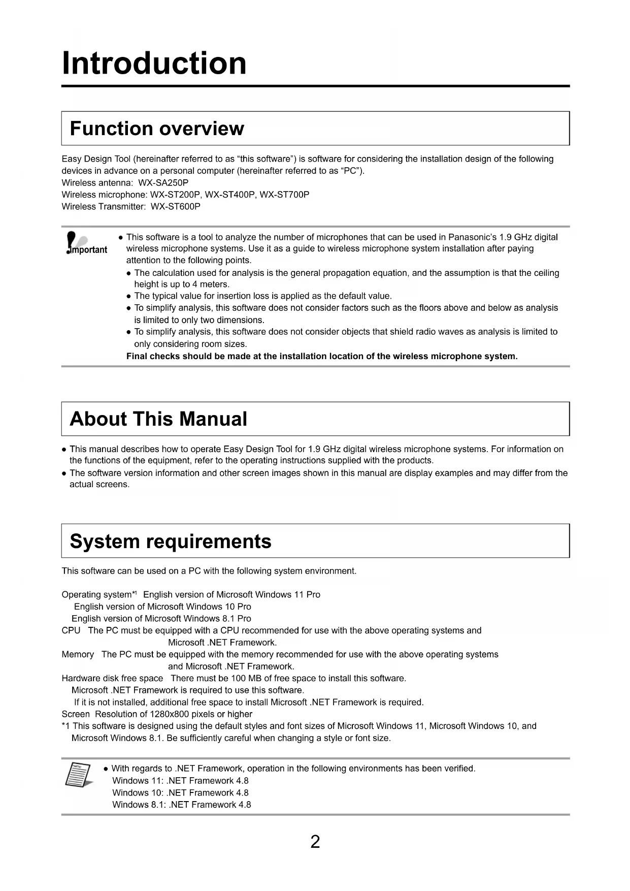
Select [Start] — [Panasonic] — [WX-SR200P Series Easy Design Tool] to start this software. This software starts and the following screen appears.
How to exit
Exit this software by selecting [File] — [Exit]. This software can also be exited from the [X] mark at the top right.
Easy wireless design operation flow
This section describes easy usage examples of this software.
Perform operation as described in the messages displayed on the screens of this software.
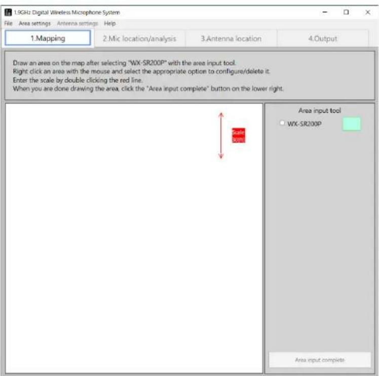
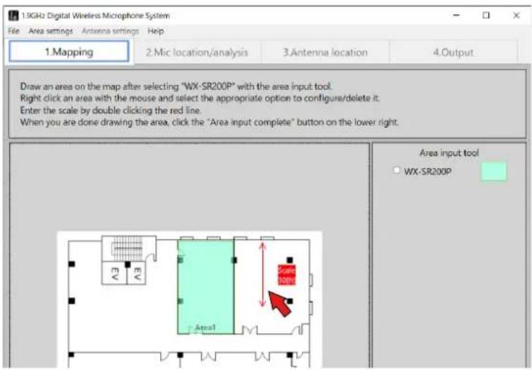
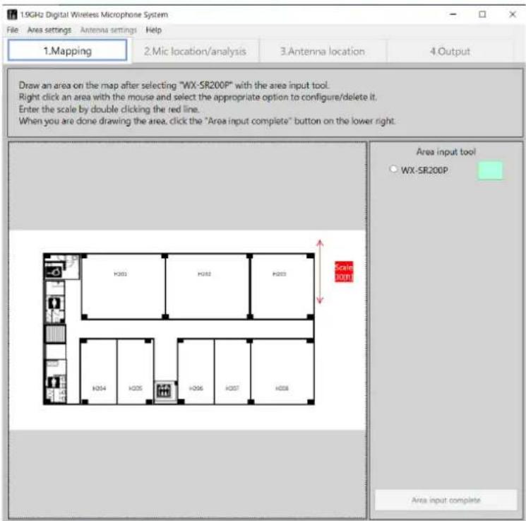
STEP1: Mapping
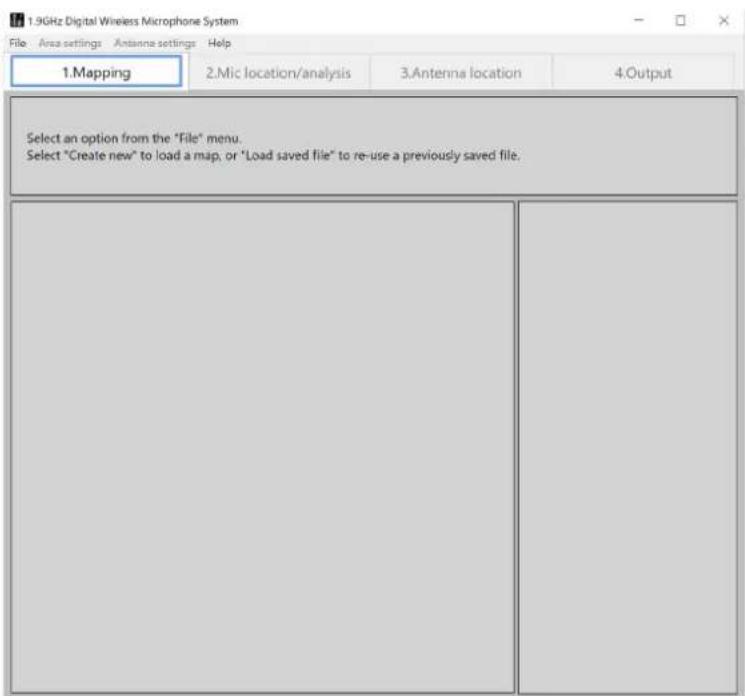
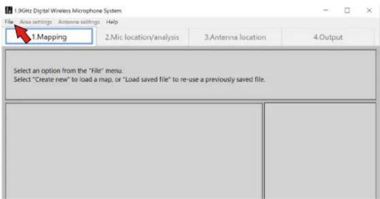
Select [File] — [Create new] — [Load map file] and then load the map of the planned installation location. If there is no map, select [No map] (a blank page area input screen will appear).
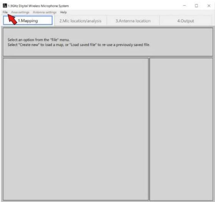

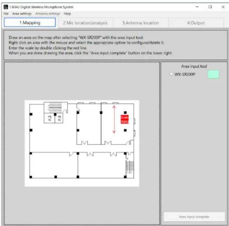
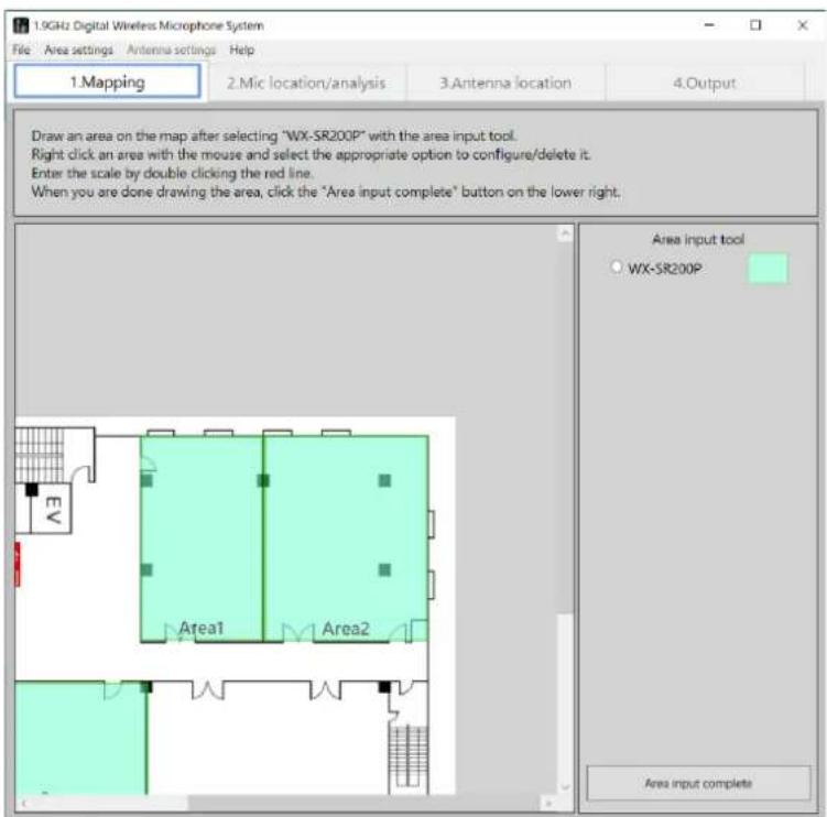
When loading of the map completes, the area input tool appears. Select the system (WX-SR200P) and input the areas to install the microphones according to the loaded map.
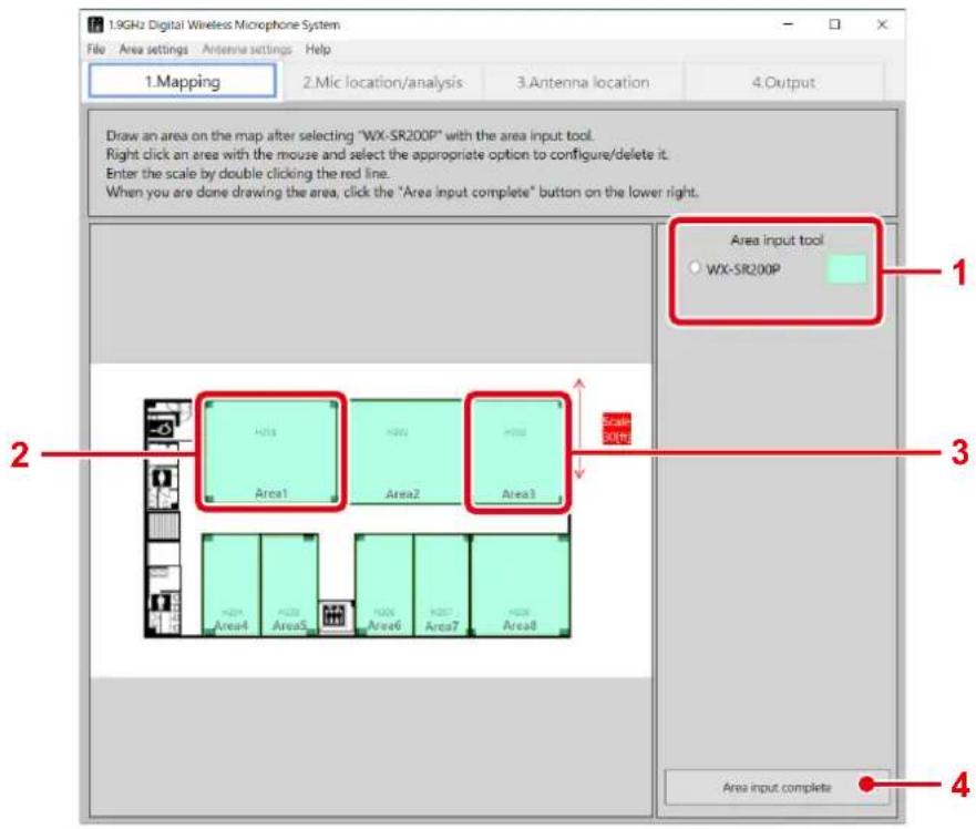
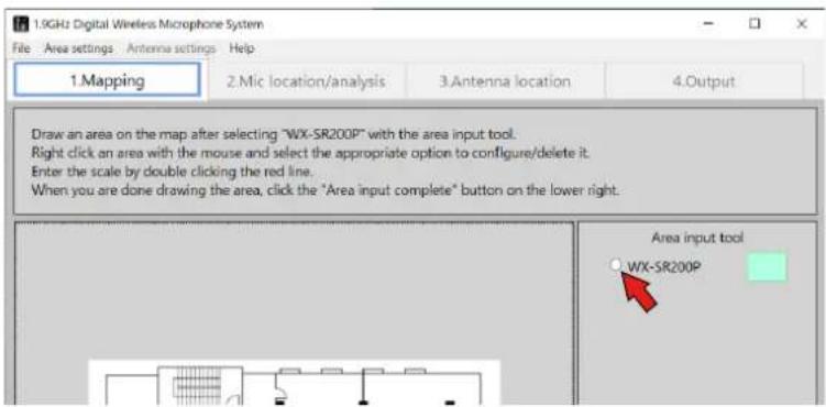
Area input procedure
1 Select the system.
Select [WX-SR200P] from the area input tool.
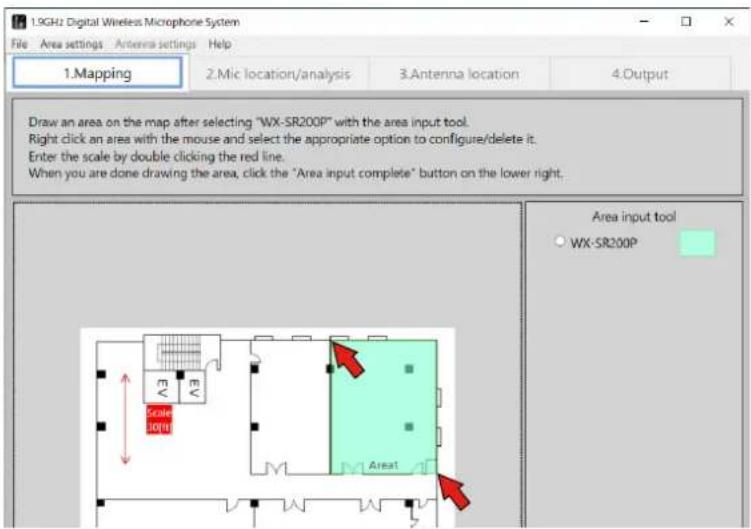
2 Input the areas.
Click the opposite angles of a room according to the map.
Repeat the above step for just the number of areas to be input.
3 Set the scale.
Adjust the length of the scale arrowed line to match the dimension.
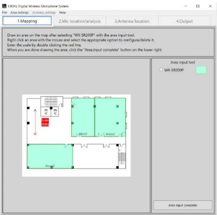
4 Complete the area input.
When area input is complete, click the [Area input complete] button.

- For details on loading maps and setting areas, refer to "Mapping" (page 14).
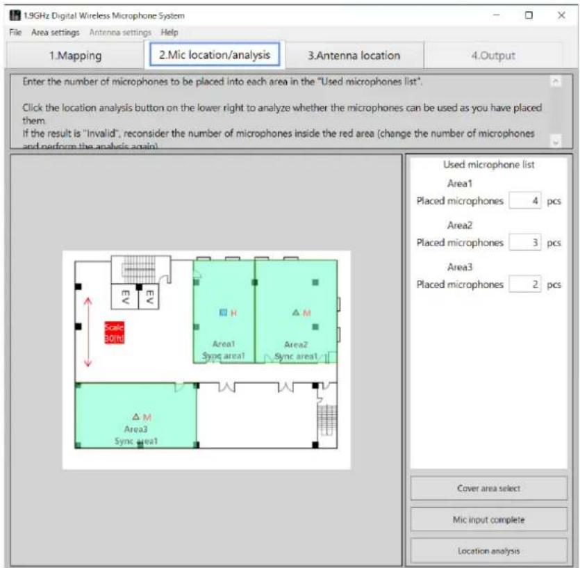
STEP2: Microphone location
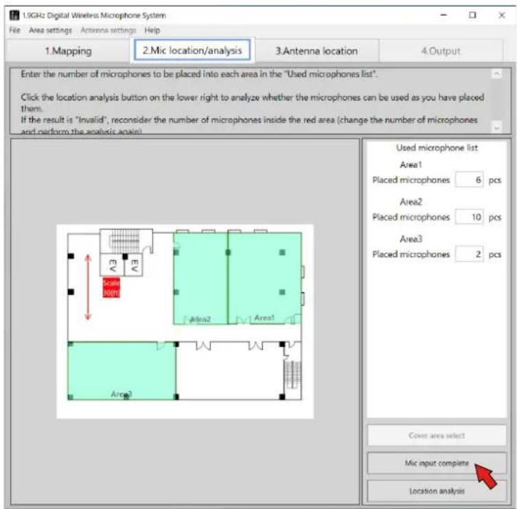
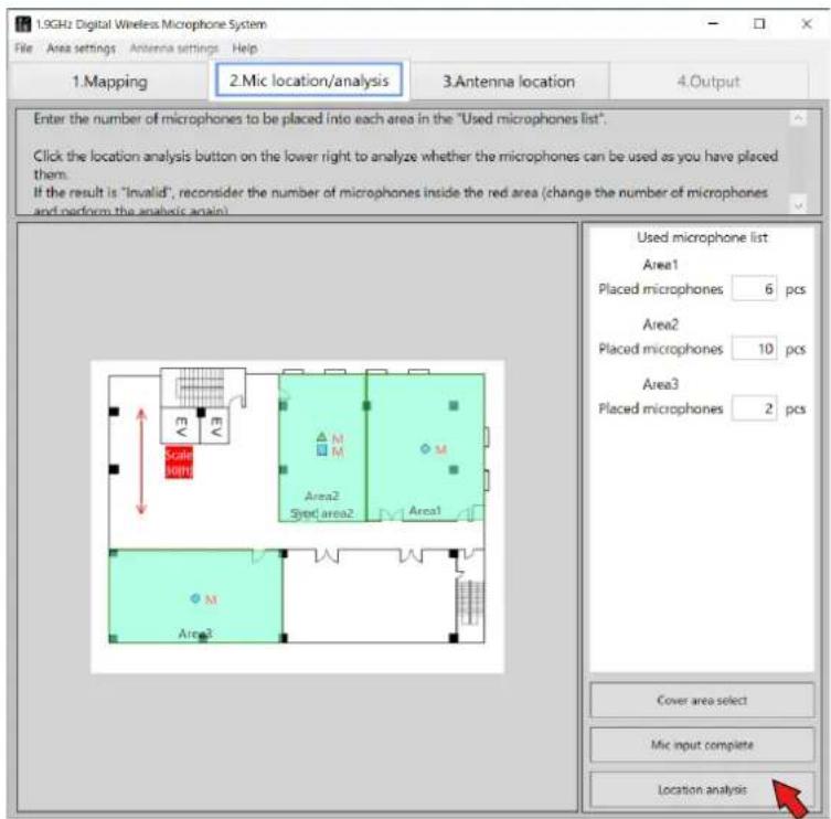
When you click the [Area input complete] button, the screen switches to the [Mic location/analysis] screen. In the [Used microphone list], input the number of microphones to be used in each area. When inputting the number of microphones is complete, click the [Location analysis] button.
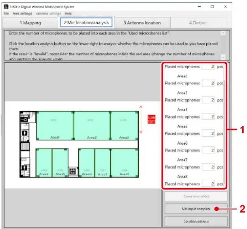
Microphone location procedure
1 Input the number of microphones.
Input the number of microphones to be used in each area in the [Used microphone list].
2 Click the [Mic input complete] button.
When microphone input is complete, click the [Mic input complete] button.
![PANASONIC WX-SA250 - Click the [Mic input complete] button. - 1](/content/2026/04/637660/images/9281a8a6059b8d198056ca968a07090b574d43bf9c66522522cdb45617cb8d4e.jpg)
- For details on microphone location, refer to "Microphone location" (page 26).
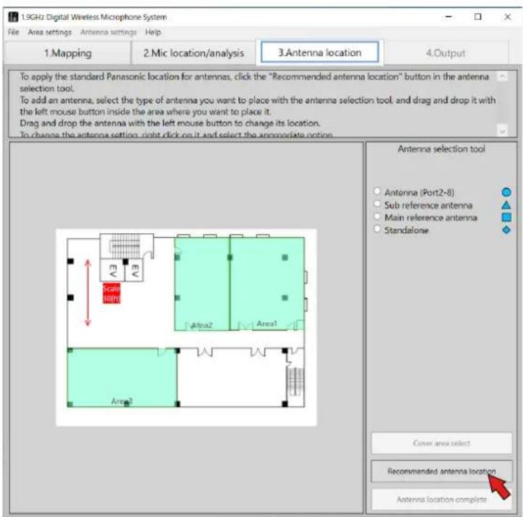
STEP3: Antenna location
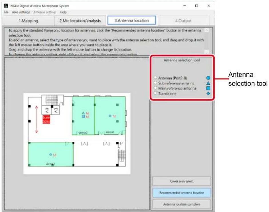
When you click the [Location analysis] button, the screen switches to the [Antenna location] screen. Click the [Recommended antenna location] button in the [Antenna selection tool].
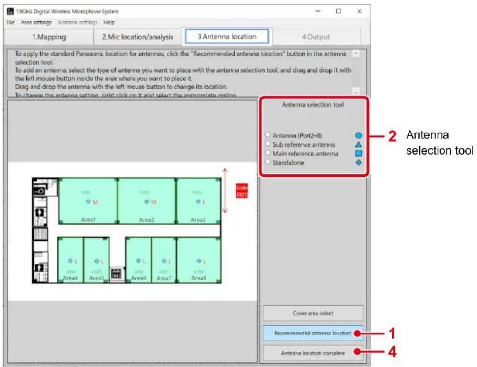
Antenna location procedure
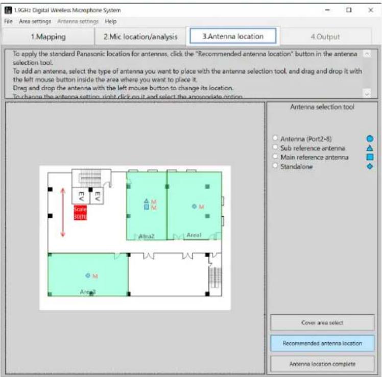
1 Click the [Recommended antenna location] button.
The recommended antennas are placed in each area.
2 Add antennas.
Select an antenna from the [Antenna selection tool] and then click in the area in which to add it. The antenna is added in the area.
3 Delete antennas.
Select an antenna to delete, right-click to display a menu, and select [Delete].
4 Complete antenna location.
Click the [Antenna location complete] button. (Click the [Antenna location complete] button to check which area each area is synchronized with and the synchronization signal level.)

- For details on antenna location, refer to "Antenna location" (page 28).
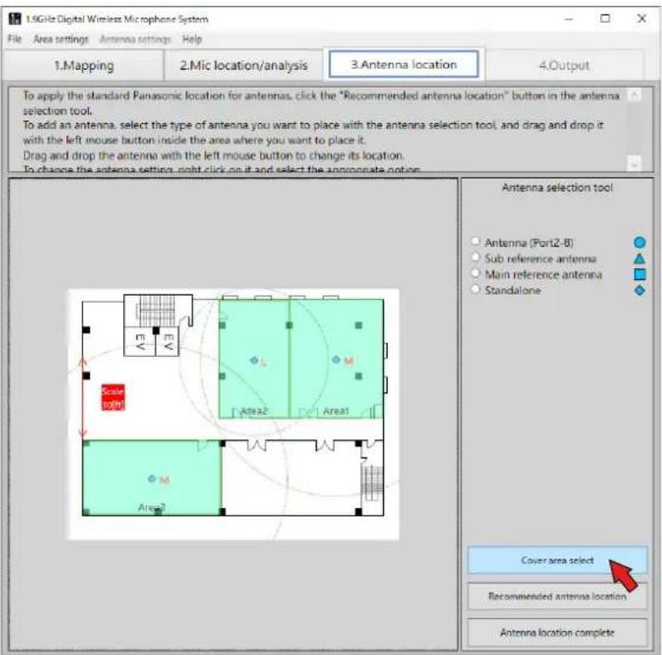
- For information about switching the display of the coverage area, refer to "About the coverage area" (page 31).
STEP4: Microphone analysis
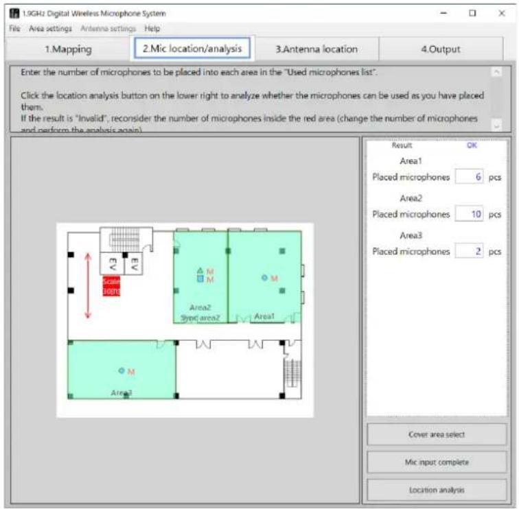
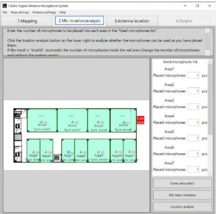
When you click the [Antenna location complete] button, the screen switches to the [Mic location/analysis] screen again. In the [Used microphone list], input the number of microphones to be used in each area. When inputting the number of microphones is complete, click the [Location analysis] button.
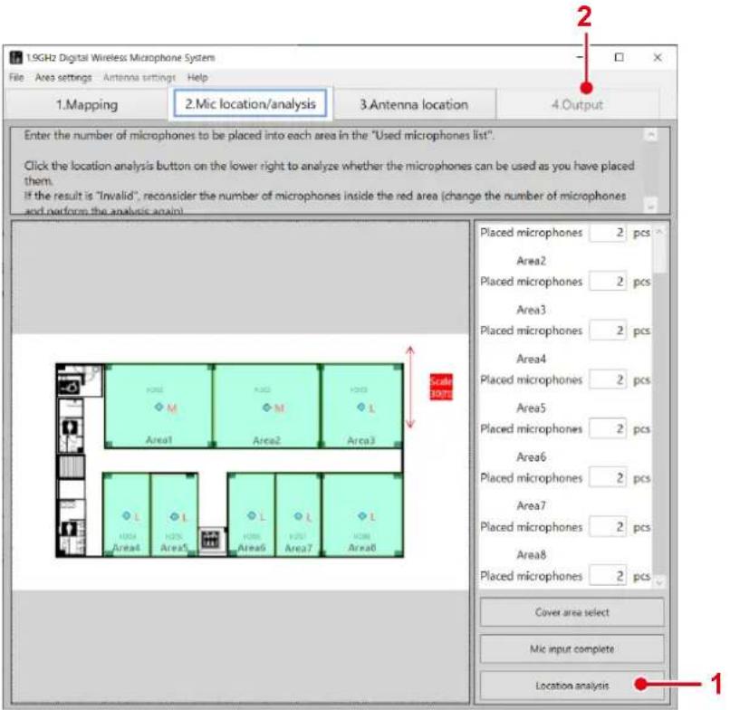
Microphone installation procedure
1 Click the [Location analysis] button.
Microphone location analysis begins. Check that the result is "OK".
If result is "NG", the number of antennas of any NG area turns red. Increase or decrease the number of microphones in the NG area and then click the [Location analysis] button again and check the number of microphones that can be used.
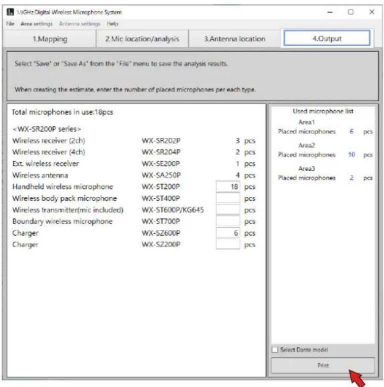
2 Select the [4.Output] tab.
The screen switches to the [Output] screen. The models and quantities required for the installed wireless system are displayed and you can create the estimate (price) and print the result.
![PANASONIC WX-SA250 - Select the [4.Output] tab. - 1](/content/2026/04/637660/images/af9f5400f886c6ebbb4a2751374ec7fbcc7a60339e2e4655c82dc74de06610c2.jpg)
- For details on microphone location and analysis, refer to "Microphone analysis" (page 39).
- For details on the [Output] screen, refer to "Print" (page 41).
- Use the results of this tool as a reference when arranging the antenna to install it around the recommended location.
- If the antenna location is decided in advance, correct the antenna location to the place where you can actually install it, and check again that there are no problems with the field selection and number of microphones used.
- For information about switching the display of the coverage area, refer to "About the coverage area" (page 31).
In the [Mapping] screen, load the map for considering the wireless microphone system installation and set the installation areas (rooms).
Loading a map (when map available)
This software allows you to load a floor plan (map) for considering wireless microphone system installation.
■ Map file load procedure
1 Load the map.
Select [File] — [Create new] — [Load map file] and then select the map of the planned installation location.
The map is displayed on the screen.
◆ Map files that can be loaded
The following map files can be loaded.
*.pdf (PDF image)
*.png (PNG image)
*.jpg (JPEG image)
*.bmp (Bitmap image)
*.gif (GIF file)

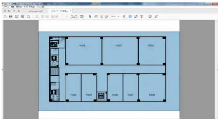
- Some PDF files may be formatted in such a way that support is not possible. (If a PDF file is not loaded, a blank screen will be displayed after loading).
In such a case, create a map file with the following procedure.
Map file creation procedure
① Open the PDF file in Acrobat Reader.
② Take a snapshot image of the map to be loaded with the selection tool.
③ Select [Start] — [All Programs] — [Accessories] — [Paint] in Microsoft Windows to start Paint.
④ Paste the snapshot captured in Acrobat Reader into Paint.
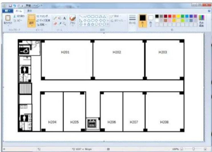
⑤ Save the file created in Paint in a file format that can be loaded as a map.
Loading a map (when map not available)
If there is no map to load into this software, select [No map]. The screen after selecting [No map] will be the blank page map screen shown below.
■ Procedure to start without a existing map
1 Select [No map].
Select [File] — [Create new] — [No map].
A blank map is displayed on the screen.
Loading a map (loading a saved file)
This software can save analysis results and load a saved file.
■ Saved file load procedure
1 Load a saved file.
Select [File] — [Load saved file] and then select the saved file.
Area input
When loading of the map completes, the area input tool appears. Input the areas in which to install the microphones according to the loaded map.
■ Area input procedure
1 Select the system.
Click the [WX-SR200P] button of the area input tool.
2 Set the areas.
To determine the area to be input, click one of the four corners and then click the corner diagonally opposite. A light purple rectangular appears and its area is input.
Input the areas of all rooms in which the WX-SR200P system is to be installed.

- The input areas can be moved and resized by dragging with the mouse.
Adding input areas
To use microphones in other areas on the map, follow the procedure in "Area input" (page 18) to set areas (rooms) where the wireless microphone system will be placed.
Enlarging the map
You can enlarge the map or revert it to the original size by holding down the "Ctrl" key and scrolling the mouse on the map. The following is an example of an enlarged map.
Changing and correcting input areas
The setting values of input areas can be changed.
Input area setting change procedure
Right-click the area for which to change the settings in the screen to display the [Settings] menu. Select the item you wish to change from the [Settings] menu.
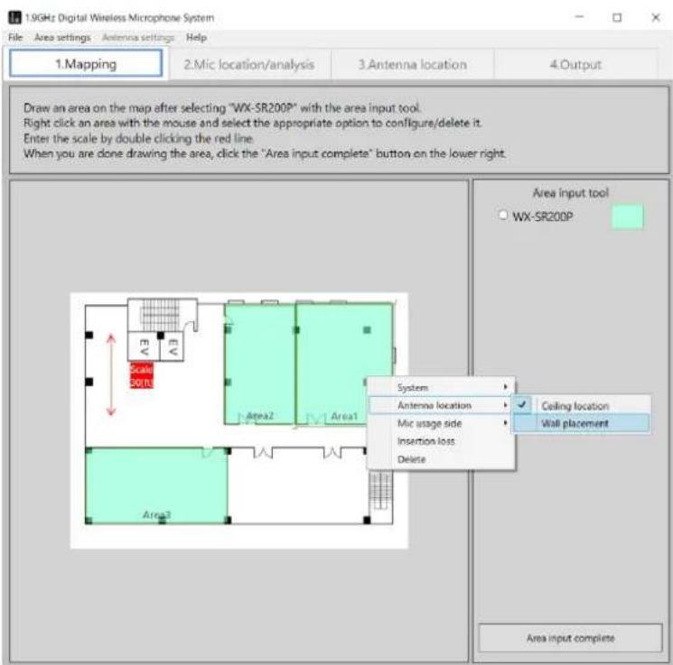
◆ [Antenna location]
The antenna installation method can be changed. The antenna installation methods use the recommended location for antennas.
[Ceiling location]: Sets the area location setting to ceiling location.
[Wall placement]: Sets the area location setting to wall placement.
Default setting: [Ceiling location]
◆ [Mic usage side]
Set whether the location to use microphones is all of the area (room) or part of the area. Normally, set this to [All].
[All]: Uses microphones in all of the area.
[Upper side]: Uses microphones in the upper side of the area.
[Lower side]: Uses microphones in the lower side of the area.
[Right side]: Uses microphones in right side of the area.
[Left side]: Uses microphones in the left side of the area.
Default setting: [All]
For example, in the case of a classroom, when microphones will be used not in all of the classroom but in the vicinity of a podium, select the location of the podium (set whether the podium is located in the upper side, lower side, right side, or left side of the area).
When other than [All] is set, this software checks the wireless reach of the antennas only for the part set as the microphone usage location. This allows you to, for example, consider cutting costs by reducing the number of antennas, etc.
◆ [Insertion loss]
Set the insertion loss of the area. If you know the materials / insertion loss of the room in which antennas are to be installed, set the insertion loss in this settings screen. If unknown, use the default.
![Set insertion loss (If you are not sure, leave it at the default (1.5) setting) Upper side Left side Right side Lower side Upper side 1.5 [dB] Lower side 1.5 [dB] Right side 1.5 [dB] Left side 1.5 [dB] OK Cancel](/content/2026/04/637660/images/a39816531f1f181c689c1207c8e893a347b642961072e24bd068de0799e5e268.jpg)
Default setting: 1.5 dB
![PANASONIC WX-SA250 - ◆ [Insertion loss] - 2](/content/2026/04/637660/images/94e3a9036189cd8a4057df20d19ea28f3580a9e2c255c95faa839a5a758108a0.jpg)
- If you know the insertion loss between areas, set 1/2 of the insertion loss as the insertion loss of the wall for each area. If we use the figure below as an example, when the insertion loss between area 1 and area 2 is known to be 10 dB, set 5 dB for the insertion loss of the lower side of area 1 and also set 5 dB for the insertion loss of the upper side of area 2.
The following table shows examples of the transmission losses of building materials.
| Material (thickness) 1900 MHz | ||
| Partition material | Wood panel (15 mm) 3.1 dB | |
| Plaster board (7 mm) 0.2 dB | ||
| Exterior wall | Brick (60 mm) 1.1 dB | |
| Slate (11 mm) 4.0 dB | ||
| Autoclaved lightweight concrete (100 mm) 9.3 dB | ||
| Heat insulation material | Heat rejection film 23.8 dB | |
◆ [Delete]
Delete an area.
![PANASONIC WX-SA250 - ◆ [Delete] - 1](/content/2026/04/637660/images/6769a39157053740fa99903ab12fe5a55e49f767aefa5b38cc14ad8180dd342e.jpg)
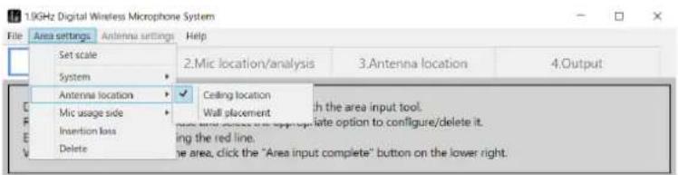
- You can also change the input area settings from [Area settings] in the menu.
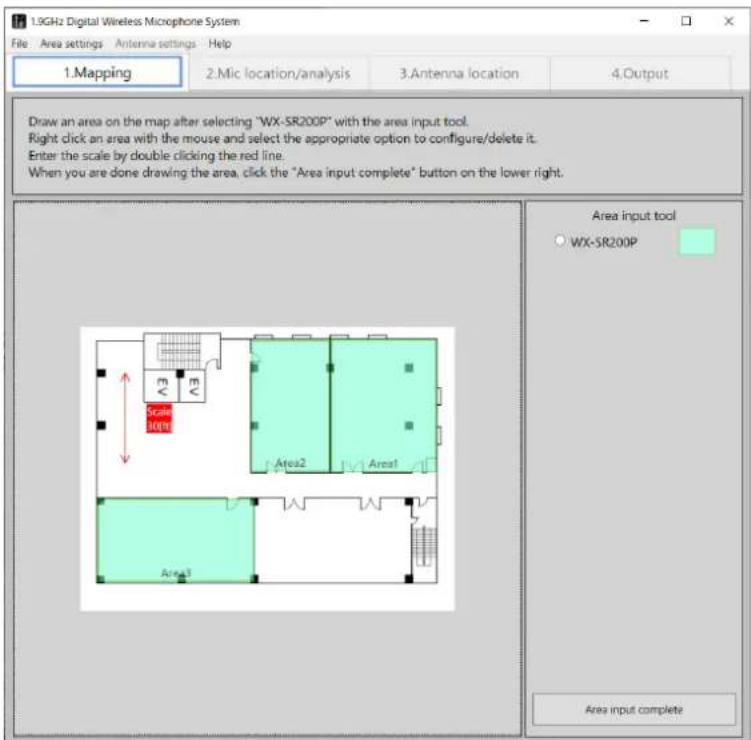
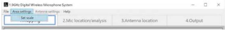
Setting the scale
Set the scale to serve as the reference dimension for input areas. The scale will be the reference for the distance to use when calculating wireless interference between placed antennas. Always set it.
■ Scale setting procedure
1 Click the scale arrowed line.
2 Adjust the angle, length, and position of the scale arrowed line.
Adjust the length and position of the scale arrowed line to match the size of the area. If you right-click the arrowed line, you can change the angle of the arrowed line. For example, if the dimension is shown on the loaded map, adjust the length of the scale arrowed line to match that dimension.

3 Input a numerical value.
If you double click the scale display area, the [Set scale] window appears. Input a numerical value.
![Set scale 30 [ft] OK Cancel](/content/2026/04/637660/images/edcf2188d0e655bf2acb73cd66b0607cddcb9f6f8073d3412c9455ae4495c7b7.jpg)

- To return to the original 0° or 90° after changing the angle of the scale, right-click the scale and select 0° or 90° from the menu.
- After clicking to select, you can also change the scale setting from [Area settings] in the menu.
Area input completion
When area input is complete, click the [Area input complete] button.
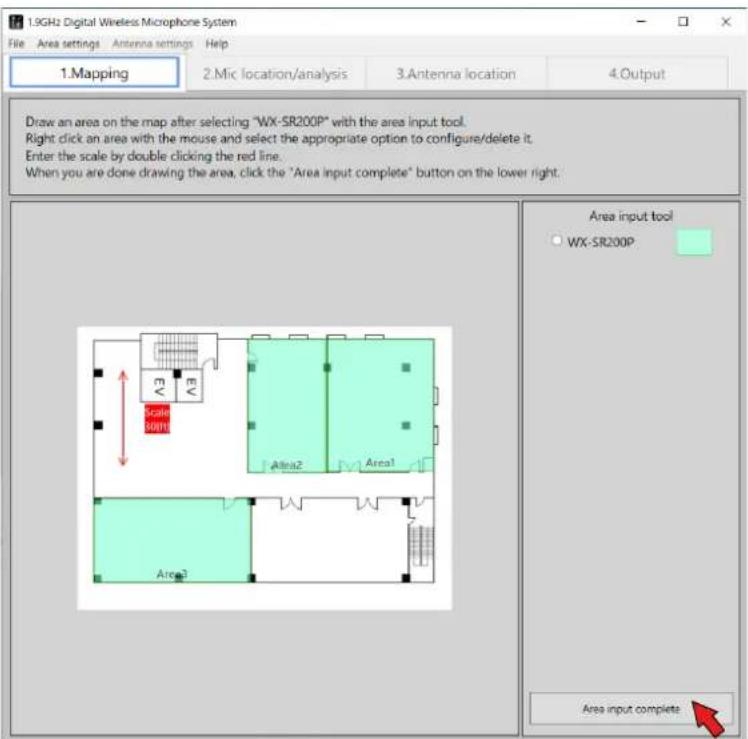
The screen switches to the [Mic location/analysis] screen.

- If you move or change an area while working on another tab ("Mic location/analysis", "Antenna location/analysis", etc.), the work tab switches to "Mapping". If you have moved, resized, or changed the settings of an area, click the "Area input complete" button to apply the changes.
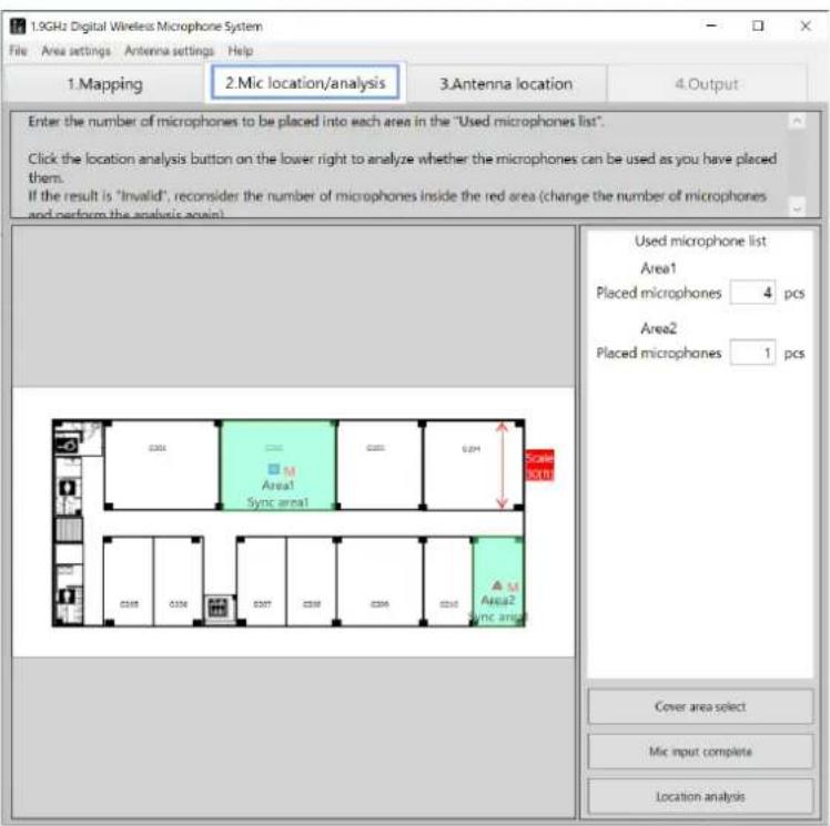
When area input completes, the screen switches to the [Mic location/analysis] screen. In the [Mic location/analysis] screen, place the microphones in each area (room).
■ Used microphone input
1 Input the number of microphones.
In the [Used microphone list] on the right side of the screen, input the number of microphones you plan to place in each area.
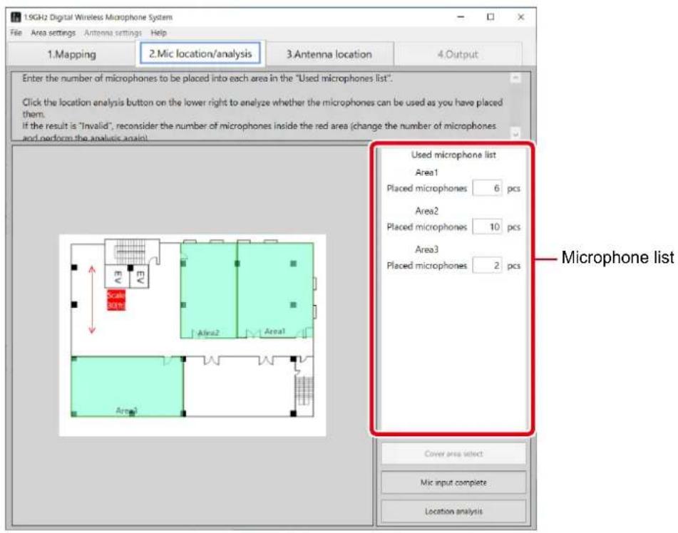
2 Complete the microphone input.
When inputting the number of microphones for each area is complete, click the [Mic input complete] button.
The screen switches to the [Antenna location] screen.
In the [Antenna location] screen, place the antennas in each area (room).
Recommended antenna location
This software proposes the recommended location for the wireless microphone system.
■ Recommended location procedure
1 Execute recommended antenna location.
Click the [Recommended antenna location] button.
The antennas are placed in the recommended positions in each area.
In recommended location, a main reference antenna and sub reference antennas are placed when the number of microphones used in an area is 9 or more.

- This software places antennas according to the number of microphones placed.
- If an area is larger than the antenna coverage area (wireless reach), the message "Reconsider the antenna location" appears after executing recommended antenna location (page 35), and then the result becomes "NG". In this case, redisplay the mapping screen, revise the size of the area for using microphones or change [Mic usage side] to place the microphones at the side where an antenna is set.
- For details on wireless synchronization (main reference antenna / sub reference antennas), refer to Operating Instructions of WX-SR202P/204P.
Number of microphones, system configuration, and antenna location example
| Number of microphones System configuration Antenna location example | ||
| Up to 2 microphones SR202P x1 |  | |
| From 3 to 4 microphones SR204P x1 |  | |
| From 5 to 6 microphones | SR202P x1SR204P x1 |  |
| From 7 to 8 microphones | SR204P x1SE200P x1 |  |
| From 9 to 10 microphones | SR202P x1SR204P x1SE200P x1 |  |
| From 11 to 12 microphones | SR204P x2SE200P x1 |  |
| From 13 to 16 microphones | SR204P x2SE200P x2 |  |
| From 17 to 18 microphones | SR202P x1SR204P x2SE200P x2 |  |
| From 19 to 20 microphones | SR204P x3SE200P x2 |  |
| From 21 to 24 microphone(maximum configuration) | SR204P x3SE200P x3 |  |
If the area is large, the necessary antennas are placed at the recommended antenna positions. The following figure is an example of 16 microphones and an example of using two systems with two WX-SR204P, WX-SE200P, and WX-SA250P.

About the coverage area
It is a feature that displays estimated antenna coverage areas (wireless reach) on the map as dotted circles. You can display and hide them by pressing the "Switch coverage area display" button after placing antennas.

- The displayed circle is an estimate, so calls are not necessarily guaranteed inside the circle.
- If the dotted circle is green, the reach is displayed as an estimate while taking the wall thickness into account.
Changing and correcting located antennas
Add antennas, delete placed antennas, or change the setting values of placed antennas according to the design plan.
Adding antennas
To add an antenna, select the antenna to add in the [Antenna selection tool] and click in the area in which to add it. An antenna of a system different to that of the area cannot be added.
Moving placed antennas
To change the position of a placed antenna, move the antenna by dragging it.
How to change the settings of placed antennas
The settings of the placed antennas can be changed.
How to change antenna settings
Right-click the antenna for which to change the settings in the screen to display the [Settings] menu. Select the item you wish to change from the [Settings] menu.
◆ [Change types]
The antenna type can be changed. The type does not need to be changed for normal use.
The following type changes are possible for the antennas within an area of the WX-SR200P.
[SR200 Antenna]: Use the antenna as other than the main reference antenna and sub reference antenna in a WX-SR200P system.
[SR200 Sub reference antenna]: Use the antenna as a sub reference antenna in a WX-SR200P system.
[SR200 Main reference antenna]: Use the antenna as the main reference antenna in a WX-SR200P system.
[SR200 Standalone]: Use the antenna as a standalone antenna in a WX-SR200P system.
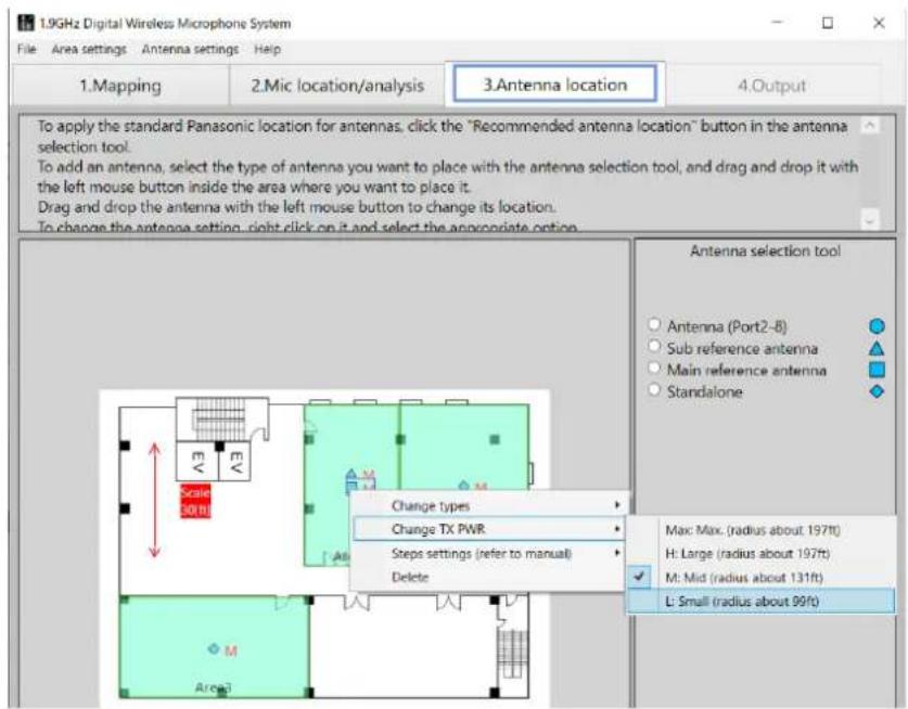
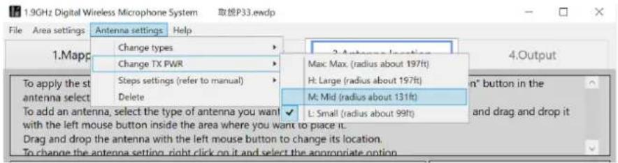
◆ [Change TX PWR]
Set the field selection of each antenna.
When the antenna type is set to [SR200 Antenna], [SR200 Sub reference antenna], or [SR200 Standalone]
[Max: Max. (radius about 131ft)]
[H: Large (radius about 99ft)]
[M: Mid (radius about 49ft)]
[L: Small (radius about 26ft)]
Default setting: [M: Mid (radius about 49ft)]
When the antenna type is set to [SR200 Main reference antenna]
[Max: Max. (radius about 197ft)]
[H: Large (radius about 197ft)]
[M: Mid (radius about 131ft)]
[L: Small (radius about 99ft)]
Default setting: [M: Mid (radius about 131ft)]
◆ Floor settings ([Steps settings])
Normally, use the system with the default settings.
[Reference antenna on floor directly below]: Select this when there is a reference antenna on the floor directly below.
[No reference antenna on floor directly below]: Select this when there is no reference antenna on floor directly below.
[Reference antenna on floor directly above]: Select this when there is a reference antenna on floor directly above.
[No reference antenna on floor directly above]: Select this when there is no reference antenna on the floor directly above.
Default settings: [No reference antenna on floor directly below] /
[No reference antenna on floor directly above]
If you select [Reference antenna on floor directly below (above)], the antenna placement analysis is made by calculating the influence from the reference antenna(s) from above and/or below floor(s). For example, if there is a reference antenna of a WX-SR200P system with a large field selection installed on the floor above, set [Reference antenna on floor directly above]. Furthermore, also set [Reference antenna on floor directly below (above)], for performing tests if there are difficult conditions such as when you think there will be influence from an antenna on the floor above or below due to an atrium space or you when think there will be influence from an adjacent building.
◆ [Delete]
Delete an antenna.
![PANASONIC WX-SA250 - ◆ [Delete] - 1](/content/2026/04/637660/images/75fd5ebe76b51bafdc5cf62ced58e9304a313d1b7aed505b5f678bb55e4ba2da.jpg)
- After clicking to select the target antenna, you can also change the antenna settings from [Antenna settings] in the menu.
Complete antenna location
When antenna location is complete, click the [Antenna location complete] button.

- If you move or change the antenna while working in other tabs (such as "Mapping" or "Mic location/analysis"), the active tab changes to "Antenna location/analysis". If you move an antenna, change the number of antennas, or change the settings, click the "Antenna location complete" button to update the changes.
◆ If an error occurs with antenna location
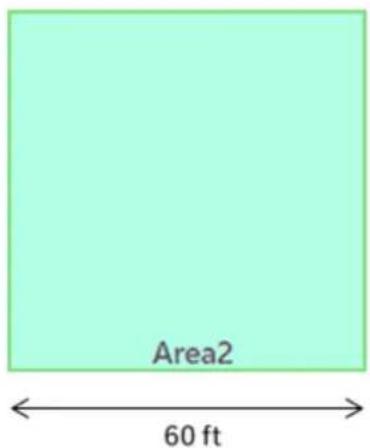
If an error occurs with antenna location, the "Reconsider the antenna location" error message appears and the area where the error occurred is indicated by a red frame as shown in the figure below.
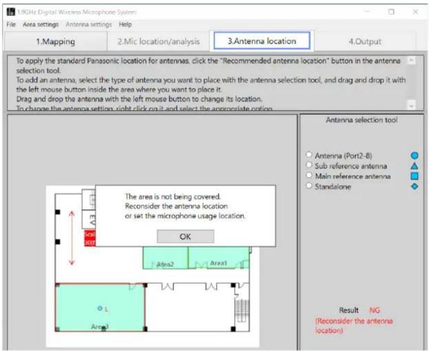
Cause of error
An error occurs because the antenna coverage area does is not large enough to cover the size of the area (room). For example, if the setting of “[Mic usage side]” (page 20) for an area is [All], an error will occur if the antenna coverage area does not extend to the four corners of the area (room).
In the case of the figure above, an error occurs because the placed antennas cannot cover to the upper side part of Area3.
Solution
Add an antenna so that the antenna coverage area is large enough to cover the entire area or revise the [Mic usage side] setting. Also perform the procedure described in "[Change TX PWR]" (page 33) if necessary.
In the case of the figure above, you need to place four antennas at ceiling height (recommended location) or set [Mic usage side] to [Lower side].
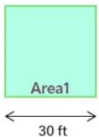
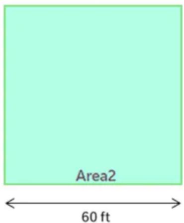
When the area size is equal to the antenna coverage area
When the size of the area is equal to 2 times the antenna coverage area (for example, when one side of the area is 30 ft, 60 ft or 120 ft as shown in the figure below), even a slight shift in the antenna location will result in an error. The reason for this is that the antenna coverage area is equal to the area size, so it is not possible to cover the four corners of the area with slight shifting.
In such a case, do not change the antenna location from the recommended antenna location, and instead change the antenna settings ("How to change the settings of placed antennas" (page 33)). For example, change the antenna type or transmission output.
Checking synchronization between antennas
If you click the "Antenna location complete" button and there are no problems with antenna placement, the "Mic location/analysis" screen is displayed and synchronization between antennas will be checked.
Which area's antenna is used as the main (reference) to synchronize for each area is displayed at the bottom of the area. In the example below, WX-SR200P Area1 is the main antenna, and is synchronized with Area2 and Area3, so it is displayed as "Sync area1".
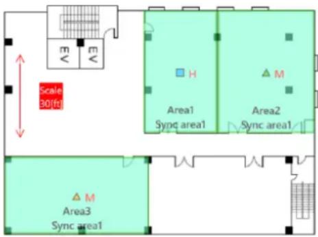
The reception strength from the main (reference) antenna is also displayed as the color of the antenna. The display settings are as follows.
▲ (Green) : Displayed in green if it is sufficiently within the coverage area of the main (reference) antenna.
Try to synchronize the antennas within this display color range.
(Orange) : Displayed in orange if the location is far from the main (reference) antenna.
For this display color, increase the field selection of the main (reference) antenna or change the antenna location.
▲ (Red) : Displayed in red if out of range of the main (reference) antenna.
The display of antennas that do not affect synchronization between antennas, such as the main (reference) or WX-SR200P system antennas, remains at the default display (displayed during antenna placement).
The figure below is an example in which the placement of synchronization between antennas needs to be revised (an example when the insertion loss between areas is relatively large). The location of the sub-reference antennas in Area1 and Area3 should be revised, as well as the field selection of the main antenna in Area2.
When antenna location completes, the screen switches to the [Mic location/analysis] screen.
Installation analysis
1 Execute installation analysis.
Check the number of microphones in each area. If you need to change the number of microphones, change it. However, after changing the number of microphones, execute "Mic input complete" and "Antenna location complete" again. After checking the number of microphones, click the [Location analysis] button.
2 Check the result.
If there is no problem with the number of microphones input for each area, "Result OK" is displayed in the [Used microphone list].
If the planned number of microphones cannot be used because, for example, there are insufficient wireless resources, "Result NG" is displayed and the number of antennas of any NG area turns red. Revise the number of microphones in the NG area and the areas surrounding it.
If the result is displayed as "NG (Too many microphones)", you must revise the number of microphones to be installed in the target area.
When installation analysis completes in the [Mic location/analysis] screen, the [Output] tab becomes able to be selected.
Select the [Output] tab to switch the screen to the [Output] screen.
In the [Output] screen, you can print the estimate.
1 Click the [Print] button.
The estimate is printed.
2 Print the analysis results.
A dialog box to confirm whether or not to also print the analysis results appears. Print the analysis results if necessary.


- A change cannot be made to a number of devices that is definitely required to construct the system.
- If you select the "Select Dante model" checkbox, the receiver and additional receiver will be changed to the Dante model.
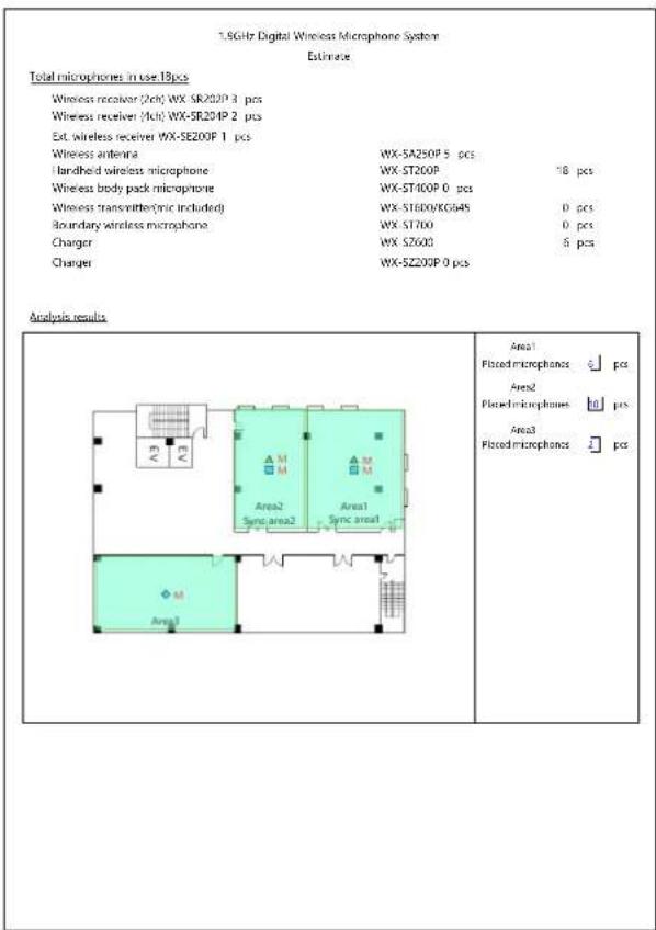
3 Check the printout.
| 1.3G-br Digital Wireless Microphone System Estimate | ||
| Total microphones in use 18pcs | ||
| Wireless receiver (2cm) WX-SR200P 3 pcs | ||
| Wireless receiver (4cm) WX-SR20HP 2 pcs | ||
| Ext wireless receiver WX-SE200P 1 pcs | ||
| Wireless antenna | WX-SA250P 5 pcs | |
| Handheld wireless microphone | WX-ST200P | 18 pcs |
| Wireless body pack microphone | WX-ST400P 0 pcs | |
| Wireless transmitter(nic include) | WX-ST600/SC64S | 0 pcs |
| Boundary wireless microphone | WX ST70D | 0 pcs |
| Charger | WX SZ600 | 6 pcs |
| Charger | WX-SZ200P 0 pcs | |
Example of printing only the estimate Example of printing the estimate and analysis results
This software allows you to save the analysis results and estimate. The work state of any screen can also be saved so you can load a file to check analysis results or resume unfinished work any time you wish. In addition, you can share files between PCs with this software installed.
Save
When you wish to save your work after opening a file saved with this software and then carrying out more work, use the save function. Select [File] - [Save].
Save as
When you wish to save your work after beginning new work in this software, use the save as function. Select [File] - [Save As]. Specify the save location and name of the file to be saved.
Checking synchronization
If the synchronized antennas are displayed in orange or red
The "Recommended antenna location" in this software suggests placing one main reference antenna. Therefore, depending on the usage environment, antenna placement may be NG (synchronized antennas are displayed in orange or red) even with the recommended antenna location.
In that case, change the antenna settings individually so that multiple main (reference) antennas are placed.
If there are multiple main (reference) antennas, the synchronization area displayed in each area after clicking the [Antenna location complete] button in the "Antenna location/analysis" screen displays the area where the main (reference) antenna with the highest reception level is located for each sub (reference) antenna.
To check if the distance allows for synchronization between antennas
To check if an area (room) can be synchronized between antennas, place the main (reference) antenna in the area that will be the reference for synchronization on the "Antenna location/analysis" screen, place the sub (reference) antenna in the area you want to check, and click the [Antenna location complete] button. Then, check the reception level with the display color of the antenna. If the reception level between the antennas is insufficient, change the field selection of the main (reference) antenna ([Change TX PWR] in "How to change the settings of placed antennas" (page 33)) or change the area (room) where the main (reference) antenna is placed, and check the reception level between the main (reference) antenna and the sub (reference) antenna with the antenna's display color.
Please check the symptoms listed in this table before requesting repair.
If the problem is not resolved by these measures or a symptom not listed in this table occurs, contact your retailer for more information.
| Symptom Cause/measure Reference | page | |
| Saved file cannot be loaded | The file may be corrupted, or you may not be using the latest version of the Easy Design Tool.→ Ask a retailer to obtain the Easy Design Tool. | 17 |
Microphone sans fil : WX-ST200P, WX-ST400P, WX-ST700P
Sortie


◆ [Antenna location]

Cartographie

◆ [Change types]
[Max: Max. (radius about 131ft)]
[H: Large (radius about 99ft)]
[M: Mid (radius about 49ft)]
[L: Small (radius about 26ft)]
[Max: Max. (radius about 197ft)]
[H: Large (radius about 197ft)]
[M: Mid (radius about 131ft)]
[L: Small (radius about 99ft)]
Cause de l'erreur

| 1.3G+Ir Digital Wireless Microphone System Estimate | ||
| Total microphones in use 18 pcs | ||
| Wireless receiver (2cm) WX-SR20P 3 pcs | ||
| Wireless receiver (4cm) WX-SR20IP 2 pcs | ||
| Ext wireless receiver WX-SE200P 1 pcs | ||
| Wireless antenna WX-SA250P 5 pcs | ||
| Handheld wireless microphone | WX-ST200P | 18 pcs |
| Wireless body pack microphone | WX-ST400P 0 pcs | |
| Wireless transmitter(nic included) | WX-ST600/SC64S | 0 pcs |
| Boundary wireless microphone | WX ST700 | 0 pcs |
| Charger | WX SZ600 | 6 pcs |
| Charger | WX-SZ200P 0 pcs | |
Panasonic Corporation of North America
Two Riverfront Plaza, Newark, NJ 07102-5490
https://na.panasonic.com/us/
Panasonic Canada Inc.
5770 Ambler Drive, Mississauga, Ontario, L4W 2T3 Canada
1-877-495-0580
https://www.panasonic.com/ca/
©P80524e8092onneR6C02815X2022

- Operating Instructions
- Function overview
- About This Manual
- System requirements
- Copyrights
- Registered trademarks and trademarks
- Abbreviations
- Software capabilities
- Terms
- WX-SR200P system
- Main reference antenna
- Sub reference antenna
- Standalone antenna
- SR200 antenna
- Symbols
- Introduction 2
- Installing and uninstalling the software 7
- Starting and exiting the software 8
- Easy wireless design operation flow 9
- Mapping 14
- Microphone location 26
- Antenna location 28
- Microphone analysis....39
- Output 41
- Saving files 43
- Example use cases 44
- Troubleshooting 46
- Installing and uninstalling the software
- How to install
- How to uninstall
- Starting and exiting the software
- How to start
- How to exit
- Easy wireless design operation flow
- STEP1: Mapping
- Area input procedure
- Select the system.
- Input the areas.
- Set the scale.
- Complete the area input.
- STEP2: Microphone location
- Microphone location procedure
- Input the number of microphones.
- Click the [Mic input complete] button.
- STEP3: Antenna location
- Antenna location procedure
- STEP4: Microphone analysis
- Microphone installation procedure
- Click the [Location analysis] button.
- Select the [4.Output] tab.
- Loading a map (when map available)
- ■ Map file load procedure
- Load the map.
- ◆ Map files that can be loaded
- Map file creation procedure
- Loading a map (when map not available)
- ■ Procedure to start without a existing map
- Select [No map].
- Loading a map (loading a saved file)
- ■ Saved file load procedure
- Load a saved file.
- Area input
- ■ Area input procedure
- Set the areas.
- Adding input areas
- Enlarging the map
- Changing and correcting input areas
- Input area setting change procedure
- ◆ [Antenna location]
- ◆ [Mic usage side]
- ◆ [Insertion loss]
- ◆ [Delete]
- Setting the scale
- ■ Scale setting procedure
- Click the scale arrowed line.
- Adjust the angle, length, and position of the scale arrowed line.
- Input a numerical value.
- Area input completion
- ■ Used microphone input
- Complete the microphone input.
- Recommended antenna location
- ■ Recommended location procedure
- Execute recommended antenna location.
- About the coverage area
- Changing and correcting located antennas
- Adding antennas
- Moving placed antennas
- How to change the settings of placed antennas
- How to change antenna settings
- ◆ [Change types]
- ◆ [Change TX PWR]
- ◆ Floor settings ([Steps settings])
- Complete antenna location
- ◆ If an error occurs with antenna location
- Cause of error
- Solution
- When the area size is equal to the antenna coverage area
- Checking synchronization between antennas
- Installation analysis
- Execute installation analysis.
- Check the result.
- Click the [Print] button.
- Print the analysis results.
- Check the printout.
- Save
- Save as
- Checking synchronization
- If the synchronized antennas are displayed in orange or red
- To check if the distance allows for synchronization between antennas
- Please check the symptoms listed in this table before requesting repair.
- Sortie
- Cartographie
- Cause de l'erreur
Brand : PANASONIC
Model : WX-SA250
Category : Microphone