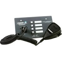
PageMatrix - Processor MediaMatrix - Free user manual and instructions
Find the device manual for free PageMatrix MediaMatrix in PDF.


User questions about PageMatrix MediaMatrix
0 question about this device. Answer the ones you know or ask your own.
Ask a new question about this device
Download the instructions for your Processor in PDF format for free! Find your manual PageMatrix - MediaMatrix and take your electronic device back in hand. On this page are published all the documents necessary for the use of your device. PageMatrix by MediaMatrix.
USER MANUAL PageMatrix MediaMatrix
natural_image
Black-and-white photo of multiple PEMATO devices including a keypad, control panel, and a remote control unit (no visible text or symbols)
Intended to alert the user to the presence of uninsulated “dangerous voltage” within the product’s enclosure that may be of sufficient magnitude to constitute a risk of electric shock to persons.

Intended to alert the user of the presence of important operating and maintenance (servicing) instructions in the literature accompanying the product.
CAUTION: Risk of electrical shock — DO NOT OPEN!
CAUTION: To reduce the risk of electric shock, do not remove cover. No user serviceable parts inside. Refer servicing to qualified service personnel.
WARNING: To prevent electrical shock or fire hazard, do not expose this appliance to rain or moisture. Before using this appliance, read the operating guide for further warnings.

2. Hardware Description ......6
2.1 PageMatrix Controller 6
2.2 Station Four-W™ 8
2.3 Station Four ^™ 10
2.4 Station Ten ^™ 11
2.5 Typical PageMatrix Connection....13
3. Software Description....14
3.1 Computer Requirements ....14
3.2 Software Installation....14
3.2.1 Launching PageMatrix....15
3.2.2 Stations and Zones....15
3.3 Menu Overview 16
3.3.1 File Menu 16
3.3.1.1 New....16
3.3.1.2 Open 16
3.3.1.3 Close....16
3.3.1.4 Save....16
3.3.1.5 Save As 16
3.3.1.6 Print 16
3.3.1.7 Print Preview 16
3.3.1.8 Print Setup....16
3.3.1.9 Download Configuration 16
3.3.1.10 Recent File 16
3.3.1.11 Exit 16
3.3.2 Edit Menu....17
3.3.2.1 Undo 17
3.3.2.2 Cut 17
3.3.2.3 Copy 17
3.3.2.4 Paste....17
3.3.2.5 Insert Station 17
3.3.2.6 Add Station 17
3.3.2.7 Delete Station 17
3.3.3 Tools Menu 18
3.3.3.1 Options 18
3.3.3.1.1 View Toolbar 18
3.3.3.1.2 View Status Bar....18
3.3.3.1.3 View Station Addresses....18
3.3.3.1.4 Max Number of Zones....18
3.3.3.1.5 Communications....18
3.3.4 Window Menu....18
3.3.4.1 New Window....18
3.3.4.2 Cascade....18
3.3.4.3 Tile 18
3.3.4.4 Arrange Icons 18
3.3.5. Help Menu....18
3.3.5.1 About Pagematrix 18
4. PageMatrix Operation ......19
4.1 Overview 19
4.1.1 The Components ....19
4.1.2 Connections....19
4.1.3 The Paging Stations....19
4.1.4 The MediaMatrix System and Pasha....20
4.1.5 Push-To-Talk Switch –What Happens?......20
4.1.6 Operation Within MediaMatrix 20
4.2 Troubleshooting....21
5. Appendix....22
5.1 Factory Support....22
5.2 Using the MediaMatrix Program Launcher 23
5.3 Station Four-W Wiring Diagrams 24
5.4 5-Pin Aux Mic Input Wiring Diagram....25
5.5 Configuring the PageMatrix Controller....26
5.6 Specifications 27
ENGLISH
1. Introduction
Congratulations on wisely choosing the PageMatrix ^™ system for your current and future paging projects. Used in conjunction with our highly-acclaimed MediaMatrix ^® digital audio system, PageMatrix provides an integrated and flexible approach to all serious paging applications.
MediaMatrix serves as the central processing unit for an entire project, controlling the entire system from signal routing to managing the paging system. The PageMatrix system provides multiple paging stations that are easily configured to just about any page/zone requirement. Plus, these paging stations are portable, meaning that the wall plug/port contains the identity of the paging station connected to it.
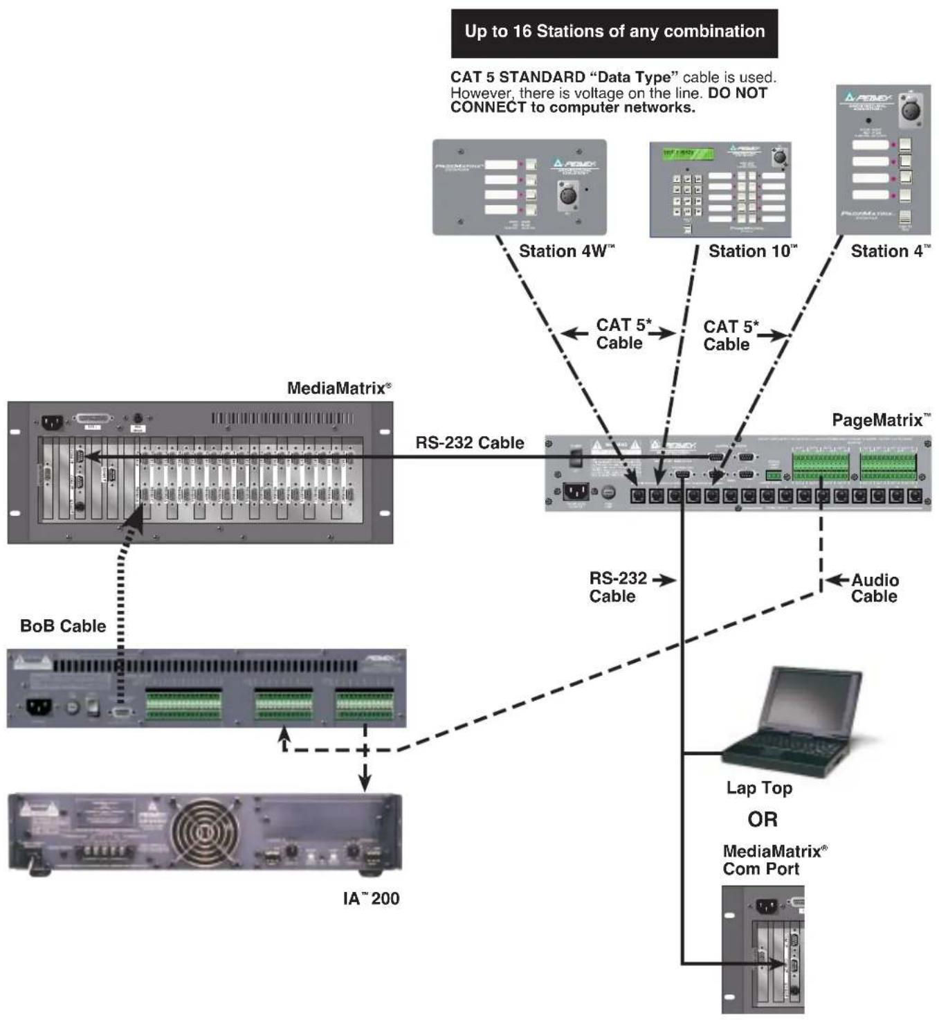
The PageMatrix hardware components include the 2-rack space PageMatrix Controller and three types of paging stations. The PageMatrix controller supports up to 16 paging stations in any combination and connects to MediaMatrix Break Out Boxes (BoBs) for audio and to the MediaMatrix frame's RS-232 serial port for control data. Three paging stations are available including the Station Four-W™ Wall Mount, Station Four™ Desktop, and Station Ten™ Desktop.
The software components include:
▲ PageMatrix Software
▲ MediaMatrix view files
▲ MediaMatrix PASHA ™ paging files (corresponds to the appropriate view file)
The PageMatrix application provides a graphical way to program the zone preset buttons of each attached station. Once the configuration is finalized, it is simply downloaded to the PageMatrix Controller for operation. It is not necessary to access the PageMatrix application again until the time comes to update the configuration.
Features
▲ 99 available page zones
▲ 16 simultaneous pages
▲ Any combination of four or ten button stations can be used.
▲ All stations feature multi-color LEDs which indicate zone preset status.
▲ Controller features a station power input for remote +24V DC operation.
▲ Phoenix connectors are used to connect paging audio to MediaMatrix BoBs.
▲ Controller supports up to four MediaMatrix systems.
▲ Controller offers 16 front panel station LEDs which indicate station status.
2. Hardware Description
2.1 Pagematrix Controller
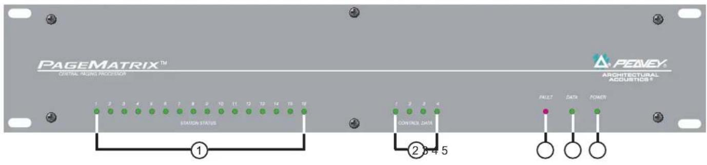
The PageMatrix controller is the heart of the system. It is connected via an RS-232 serial port to the MediaMatrix frame running MediaMatrix and PageMatrix software. In fact, one PageMatrix controller can control up to four separate MediaMatrix systems (four control data ports are provided). In addition to the control ports, a single program port is available to receive data from the PageMatrix software. Typically, the PageMatrix configuration is designed and downloaded to the controller, then disconnected from the program port.
The PageMatrix controller supports up to 16 unique paging stations including any combination of the Station Four-W™, Station Four™, and Station Ten™.
text_image
PAGEMATRIX™ CENTRAL RACING PROCESSOR 1 2 3 4 5 6 7 8 9 10 11 12 13 14 15 16 STATION STATUS 1 2 3 4 5 CONTROL DATA PEAMEY® ARCHITECTURAL ACQUISICS® FAULT DATA POWERFront Panel
- Station Status LEDs: (16) Displays green after software activation.
- Control LEDs: (4) Lights up green when the control data ports are in use.
- Fault LED: Download error indication when downloading the PageMatrix configuration to the PageMatrix controller. When this message occurs, download the configuration again.
- Data LED: Indicates a data transfer to the unit or that valid data exists in memory at power up.
- Power : Indicates that the unit is on.
text_image
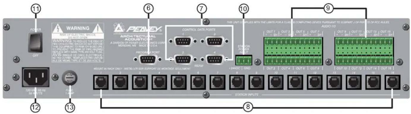
POWER OFF WARNING RISK OF ELECTRIC SHOCK SINUT OPEN WARNING TO REDUCE THE RISK OF FIRE ON ELECTRIC SHOCK DO NOT EXPOVE THIS EQUIPMENT TO RUN OR MOUNTURE TO PROTECT THE RISK OF VILL BEANS REPLACE WITH NAME TYPE 80% NO. 5 AVIX: INBIQUE DE CHNG ELECTRIOUS NETTING CENTER, REPRECERATION OFFOR BEVE MEES TYPE 80% NO. 5 PROGRAM PORT CONTROL DATA PORTS 1 2 3 4 RES230 STATION INPUTS OUT 1 | OUT 2 | OUT 3 | OUT 4 | OUT 5 | OUT 6 | OUT 7 | OUT 8 | OUT 9 | OUT 10 | OUT 11 | OUT 12 | OUT 13 | OUT 14 | OUT 15 | +2AOC | GND 10 11 12 13 14 15 16 17 18 19 20 21 22 23 24 25 26 27 28 29 30 31 32 33 34 35 36 37 38 39 40 41 42 43 44 45 46 47 48 49 50 51 52 53 54 55 56 57 58 59 60 61 62 63 64 65 66 67 68 69 70 71 72 73 74 75 76 77 78 79 80 81 82 83 84 85 86 87 88 89 90Rear Panel
- Program Port (RS-232): Accepts PageMatrix software data from the host computer's serial port (Com 1 or Com 2).
- Control Data Ports (4 RS-232 jacks): Allows connection and control of up to four MediaMatrix systems.
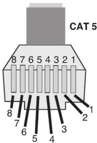
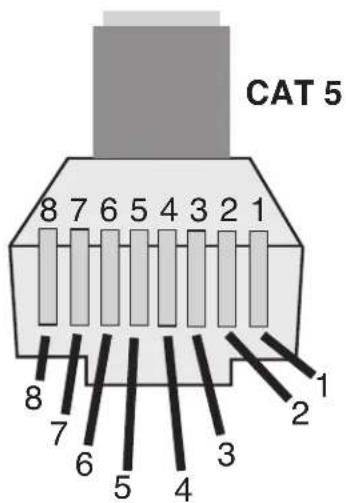
- Station Inputs (16 RJ45 jacks): All stations are connected to one of the sixteen station inputs using standard CAT 5 cable. The cable carries audio from the station and control data to and from the station, as well as power for the station. Note: This is not a network connection.
- Audio Outputs: Four removable "Phoenix" style connectors are provided for connection of audio to MediaMatrix Break out Box. Note: Two BoBs (8 channels each) are required for 16 stations.
- Station Power Input: +24V DC input for emergency station power.
Note: In the event of a power loss to the paging controller, the station power input will power only the stations to allow audio to pass in an emergency situation. In this case, the stations will be unable to communicate with the controller, and the controller will be unable to send control information to the MediaMatrix unit. In the event of a power loss, the MediaMatrix view file must be configured to route the audio without control input from the PageMatrix controller. In order for both the controller and stations to remain active, the controller must be connected to some form of power backup system, such as a UPS.
- Power Switch: Use to turn the unit on or off.
- Detachable Power Cord Connector
- Fuse: 1A at 100V/120V AC\~, T1A/250V

500 mA at 230V AC\~, T500mA/250V
2.2. Station Four-W™ Wall-Mount Paging Station
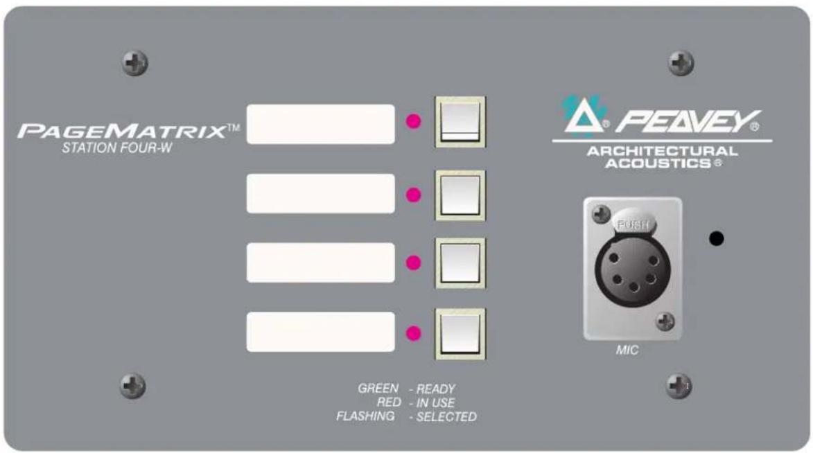
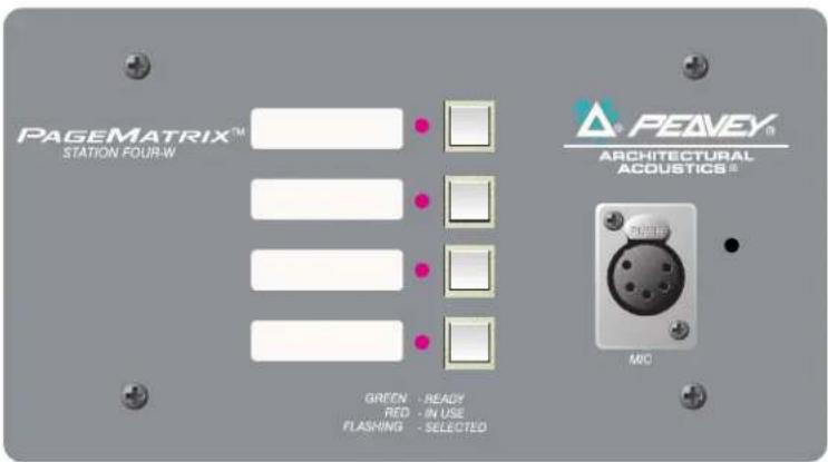
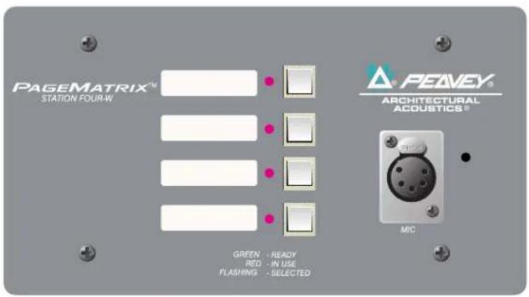
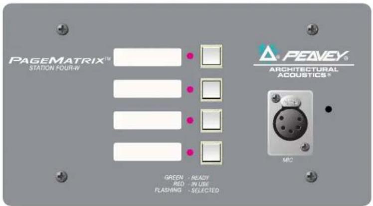
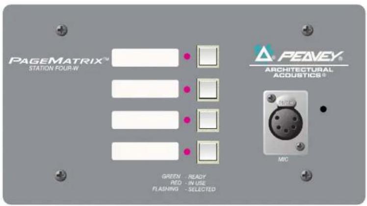
Station Four ^™ -W is a four button wall mount station that includes a hand-held (5-pin) microphone with a push-to-talk switch. Each of the four zone presets are defined and programmed by the PageMatrix software.
text_image
PAGEMATRIX™ STATION FOUR-W PEAVEY® ARCHITECTURAL ACOUSTICS® MIC GREEN - READY RED - IN USE FLASHING - SELECTEDFront Panel
Zone Preset buttons w/LEDs(4):
Used to select any of the four zone presets. A green LED indicates the zone is available, while a red LED indicates it is in use by another station. The LED will blink to confirm the selection.
Five-pin Mic Input:
Used to connect the supplied 5-pin handheld microphone.
Mic Volume:
Recessed to the right of the microphone input, use a small screwdriver to adjust the mic gain.
Rear Panel
3-Pin Connector:
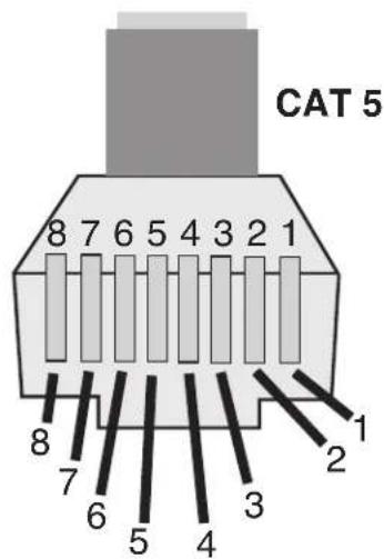
This is the analog audio signal output to be connected to the PageMatrix controller. See the wiring diagram, Appendix 5.3.
4-Pin Connector:
This connects the control data to and from the PageMatrix controller and also the power for the station. See the wiring diagram, Appendix 5.3.
Station Four-W Operation
▲ LED color indicates status of each of the four Zone presets.
▲ Green indicates the zone is available and not in use by another station.
▲ Red indicates the zone is in use.
When the microphone "Talk" button is pressed, the selected zone preset LED turns orange to confirm that it is active. Other stations connected to the system will indicate RED to confirm that this particular zone is in use.
▲ Press any Zone Preset button to select. The LED will blink confirming the selection.
At power-up, the unit defaults to zone one and after one minute of inactivity reverts back to zone one.
▲ Hand-held 5-pin mic input is activated by pressing the "talk" button.
▲ Zone presets can be labeled in the appropriate white boxes.
▲ If all LEDs flash red at power up, this indicates the station has not been programmed.
▲ If all LEDs flash green at power up, this indicates the station has been programmed.
About Zone Presets
MediaMatrix defines the zones which can represent single outputs or groups of outputs. PageMatrix software is used to program the button assignments on the paging stations which enables them to access one or more zones per button. We refer to the button assignments as zone presets, since these settings are set initially. They are then downloaded to the PageMatrix controller where they become active.
About Priority
With PageMatrix, there are no inherent priority settings. Any microphone may be used at any time and the “busy” LED indication identifies when a zone preset is in use by another station. However, extensive priority levels can be configured and designed within MediaMatrix.
|2.3. Station Four™ Desktop Paging Station
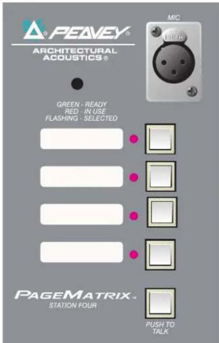
Station Four ^™ is a four button desktop station that includes an electret condenser microphone. Each of the four button zone presets are defined and programmed by the PageMatrix software.
text_image
PEAVY® ARCHITECTURAL ACOUSTICS® GREEN - READY RED - IN USE FLASHING - SELECTED PAGE MATRIX® STATION FOUR PUSH TO TALK MICFront Panel
Push To Talk button:
Press and hold to enable the microphone for the selected zone preset. The selected LED will turn orange to denote active status while the other zone preset LEDs become red.
Zone Preset buttons w/ LED(4):
Used to select any one of the four zone presets. A green LED indicates the zone is available, while a red LED indicates it is in use by another station. The LED will blink to confirm selection.
XLR Mic Input:
Phantom powered microphone input
Mic Volume:
Recessed mic gain adjustment
Rear Panel
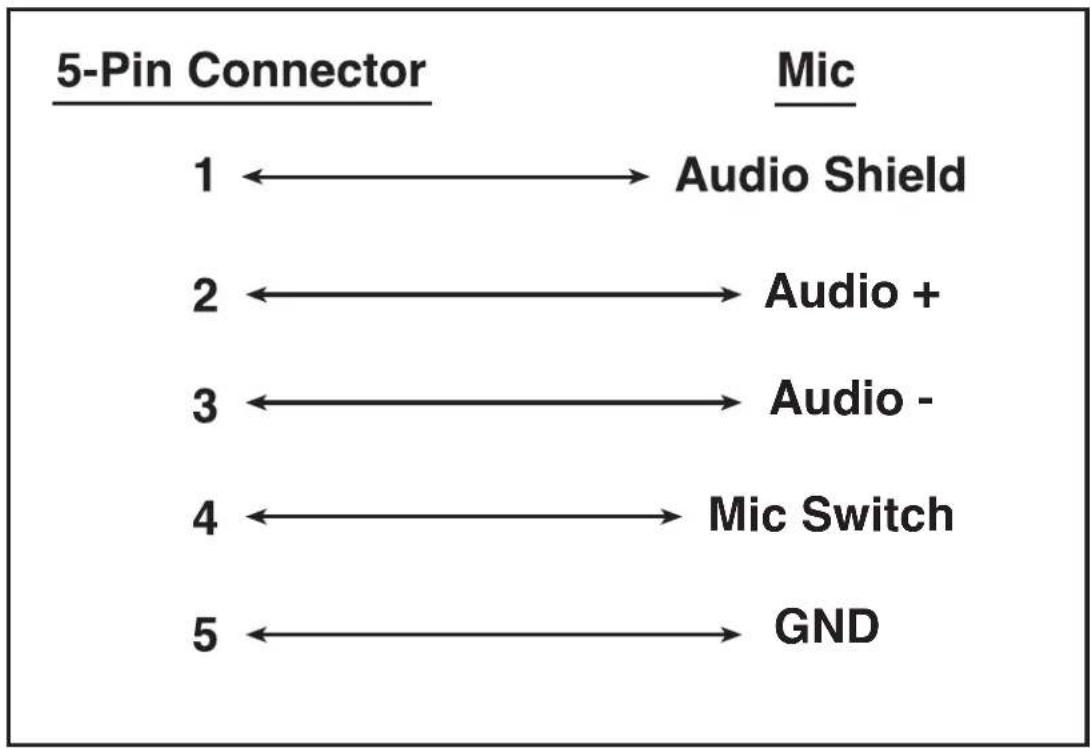
5-pin Aux Mic Input
For connection of a remote microphone with a push-to-talk feature. See the wiring diagram, Appendix 5.4. The aux mic is automatically routed to zone preset one.
Station Four Operation
▲ LED color indicates status of each of the four Zone presets.
▲ Green indicates the zone is available and not in use by another station.
▲ Red indicates the zone is in use.
▲ When the Push To Talk button is pressed, the selected zone preset LED turns orange to confirm that it is active. Other stations connected to the system will indicate RED to confirm that this particular zone preset is in use.
▲ Press any zone preset button to select. The LED will blink confirming the selection.
At power-up, the unit defaults to zone one and after one minute of inactivity reverts back to zone one.
▲ Zone presets can be labeled in the appropriate white boxes.
▲ If all LEDs flash red at power up, this indicates the station has not been programmed.
▲ If all LEDs flash green at power up, this indicates the station has been programmed.
▲ The Aux mic input (rear panel) is always routed to zone preset one.
|2.4. Station Ten™ Desktop Paging Station
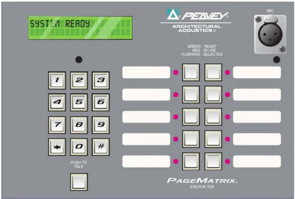
Station Ten™ is a ten button desktop station that includes an electret condenser microphone. Each of the ten zone presets are defined and programmed by the PageMatrix software. In addition, a 12 button “telephone style” key pad and 20 x 2 LCD panel are provided for selection and indication of up to 99 “virtual” zones. The ten buttons are unique for each station; however, the additional 89 “virtual” dial-up zones are the same (global) for each Station Ten unit connected to the PageMatrix controller. Each of these zone presets are defined and programmed by the PageMatrix software.
text_image
SYSTEM READY PEAVEY® ARCHITECTURAL ACOUSTICS® MIC FLASH GREEN - READY RED - IN USE FLASHING - SELECTED 1 2 3 4 5 6 7 8 9 * 0 # PUSH TO TALK PAGE MATRIX. STATION TENFront Panel
Push To Talk button:
Press to activate the microphone for the selected zone preset.
Zone Preset buttons w/ LED(10):
Used to select any of the ten zone presets. A green LED indicates the zone is available, while a red LED indicates it is in use. The LED will blink to confirm selection.
XLR Mic Input:
Phantom powered microphone input.
Mic Volume:
Recessed mic gain control.
Rear Panel
Aux Mic Input (5-pin):
For connection of a remote microphone with a "Push-To-Talk" feature. See wiring diagram, Appendix 5.4. The aux mic is automatically routed to zone preset one.
RJ45 Connector:
For connection to the PageMatrix controller.
Station Ten Operation
▲ LED color indicates status of each of the ten zone presets.
▲ Green indicates the zone is available and not in use by another station.
▲ Red indicates the zone is in use.
▲ When the Push To Talk button is pressed, the selected zone preset LED turns orange to confirm that it is active. Other stations connected to the system will indicate RED to confirm that the zone preset is in use.
▲ Press any Zone Preset button to select. The LED will blink confirming the selection.
▲ At power-up, the unit defaults to zone one.
▲ Aux Mic input (5-pin) on the back panel is programmed for zone preset one.
▲ For direct zone preset access, the key pad can be used. Simply enter a one or two digit number, then press # to select.
▲ The selected zone name (user nameable up to 16 characters within the PageMatrix software) will be displayed on the 20 x 2 LCD in addition to status (ready/busy/paging)
▲ The upper line of the display provides the station name and status. The second line provides the zone name.
▲ Zone presets can be labeled in the appropriate white boxes.
▲ If all LEDs flash red at power up, this indicates the station has not been programmed.
▲ If all LEDs flash green at power up, this indicates the station has been programmed.
At power-up, the unit defaults to zone one and after one minute of inactivity reverts back to zone one.
About Zone Presets
MediaMatrix defines the zones which can represent single outputs or groups of outputs. PageMatrix software is used to program the button assignments on the paging stations which enables them to access one or more zones per button. We refer to the button assignments as zone presets, because these settings are set initially then downloaded to the PageMatrix controller where they become active.
About Priority
With PageMatrix, there are no inherent priority settings. Any microphone may be used at any time and the “busy” LED indication identifies when a zone preset is in use by another station. However, extensive priority levels can be configured and designed within MediaMatrix.
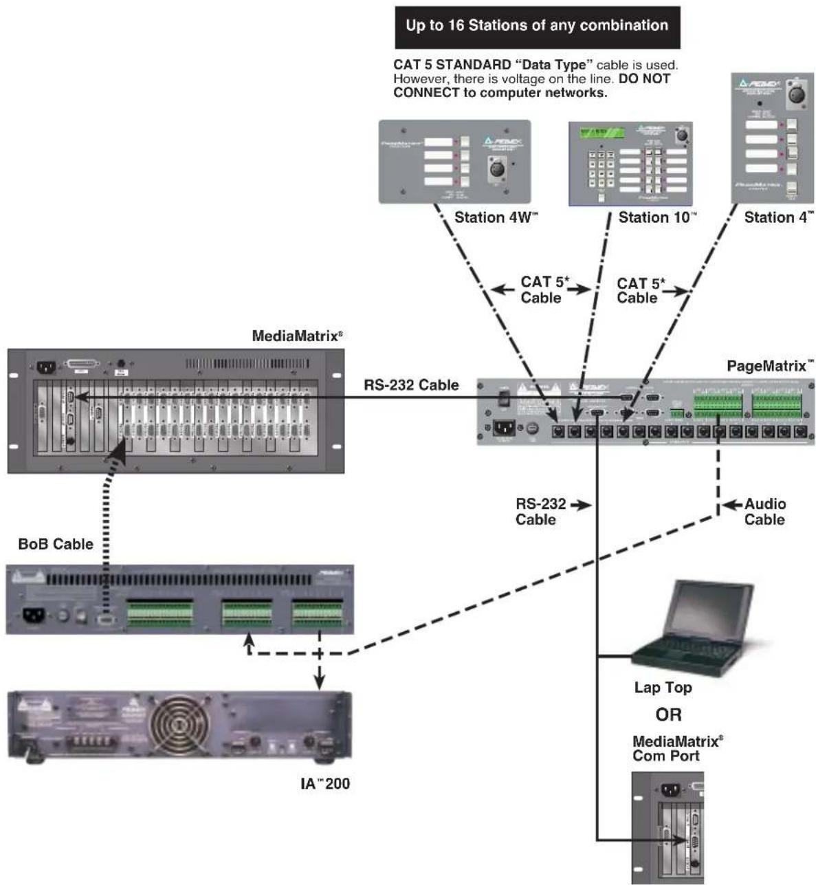
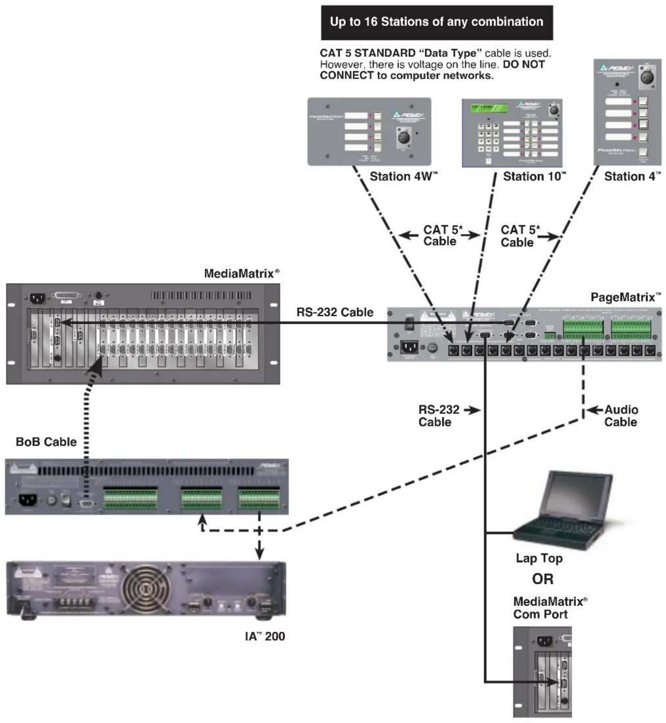
2.4. Typical PageMatrix Connection
flowchart
graph TD
    A["Up to 16 Stations of any combination"] --> B["Station 4W™"]
    A --> C["Station 10™"]
    A --> D["Station 4™"]
    B --> E["RS-232 Cable"]
    C --> F["RS-232 Cable"]
    D --> G["PageMatrix™"]
    H["MediaMatrix®"] --> I["BoB Cable"]
    J["IA™ 200"] --> K["Bus"]
    L["Cat 5* Cable"] --> M["Station 4W™"]
    N["Cat 5* Cable"] --> O["Station 10™"]
    P["Lap Top OR MediaMatrix® Com Port"] --> Q["Audio Cable"]
3. PageMatrix Software Description
text_image
Peavey PageMatrix - Config1 File Edit Tools Window Help Config1 Station1 Zone Name: Zone1 Station2 01 02 03 04 05 06 07 08 09 10 1 HB-01 HB-02 HB-03 HB-04 For Help, press F1 NUM3.1. Computer Requirements
Minimum: 486DX-100 or faster PC with Windows 3.1 / 95 / NT4 or later, 8-16Mb RAM and one available Com Port.
3.2. Software Installation
Note: With MediaMatrix Mainframe systems shipped since 1999, the PageMatrix application is already installed. The instructions below only apply to systems prior to this time.
The complete PageMatrix software system includes:
- PageMatrix application (Floppy Disk 1)
- MediaMatrix view files and PASHA™ files (Floppy Disk 2)
- MediaMatrix devices (Floppy Disk 2)
Step One: Installing the PageMatrix software (files in parentheses indicate defaults)
A. Insert Disk One (PageMatrix Installation) into the floppy drive.
B. Run "A:\setup.exe".
C. Will prompt for an installation directory (c:\pagemtrx) and a program group name (PageMatrix). Installs files in that directory and creates program group. When installation window says "Installation Complete!" in red, click the Finish button or cancel button (if there is no finish button). You do not need to restart your computer after installation.
Step Two: Installing the MediaMatrix view files:
Note: When installing the PageMatrix view files and devices, you will need to know what directory your MediaMatrix software is in (if it is in a different directory than the factory defaults).
A. Insert Disk Two (MediaMatrix view Files) into the floppy drive.
B. Run "A:\views.exe".
C. This is a self-extracting zip file that will ask you for a directory to place the unzip files. These files can go anywhere on your hard drive, but it is recommended that you install them in the View directory in your MediaMatrix root directory(c:\peavey\views).
D. Once the directory is confirmed, click Unzip.
E. Click Close when finished.
Step Three: Installing the MediaMatrix devices
A. Insert Disk Two (MediaMatrix view Files) into the floppy drive.
B. Run "A:\devices.exe".
C. This is a self-extracting zip file that will ask you for a directory to place the unzip files. These files MUST go in the Devices directory in your MediaMatrix root directory (c:\peavey\devices\standard\paging) If your root directory is different from the default, enter the proper root directory followed by "devices\standard\paging".
D. Once the directory is confirmed, click Unzip.
E. Click Close when finished.
3.2.1. Launching PageMatrix
Windows 95:
- Under the Start menu, select Programs.
- Find the PageMatrix directory and select it.
- Locate PageMatrix, and select it.
Windows 3.1:
- Find the PageMatrix Program Group within the Program Manager
- Doulbe click the group, then double click the PageMatrix Icon.
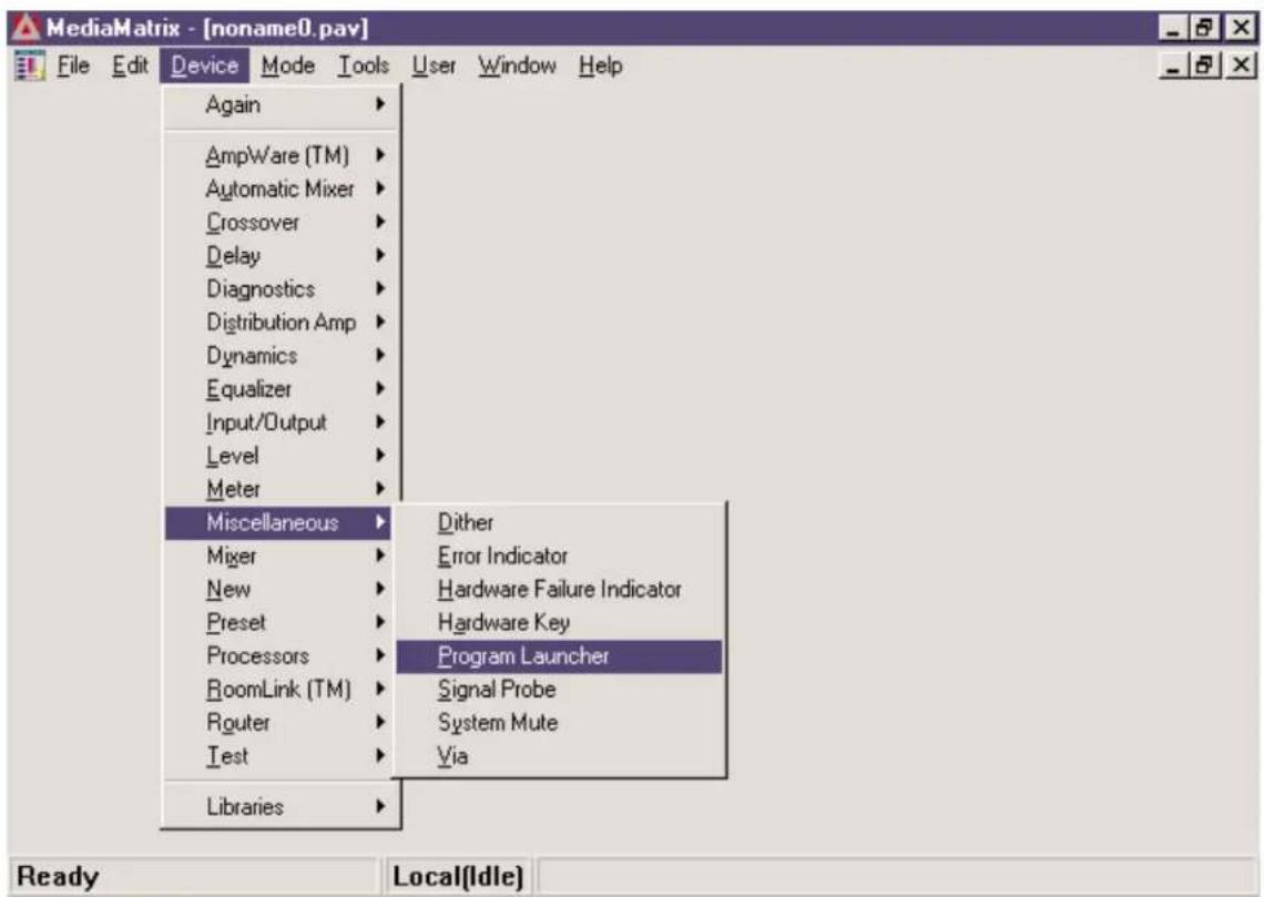
Note: For systems that are not pre-loaded with PageMatrix, the MediaMatrix Program Launcher can be used. This is found under the MediaMatrix Device/Miscellaneous menu. See appendix 5.2.
3.2.2. Stations and Zones
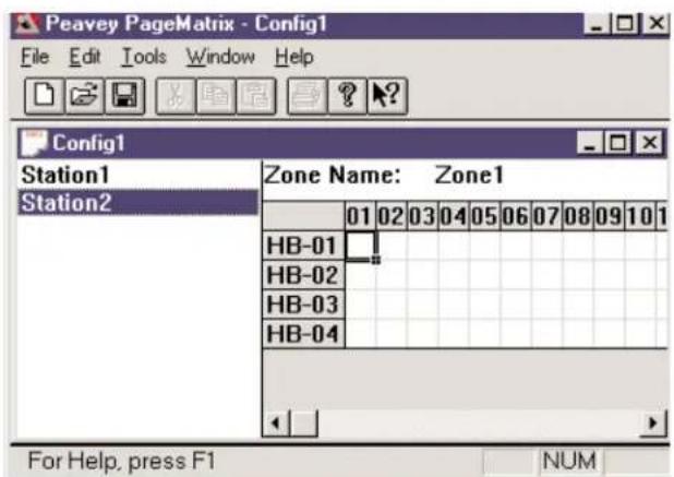
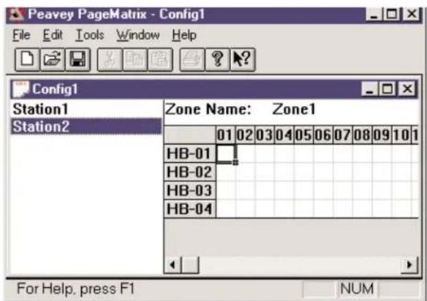
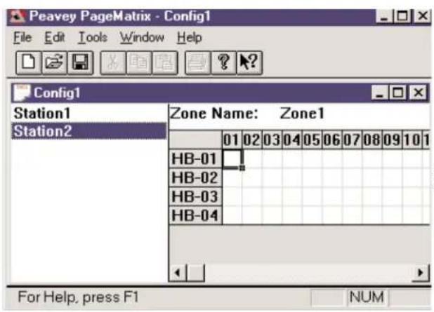
The PageMatrix application simplifies the process of programming the remote stations. A grid matrix is presented that lists each button for the selected station. HB stands for hardware button and the following number signifies the specific button on the station. Station buttons are displayed in rows and potential zone assignments in columns.
To assign the button, simply left-click the desired zone to select it (a bold outline appears around the selection), then right-click to confirm (turns red).
text_image
Peavey PageMatrix - Config1 File Edit Tools Window Help Config1 Station1 Zone Name: Zone1 Station2 01 02 03 04 05 06 07 08 09 10 1 HB-01 HB-02 HB-03 HB-04 For Help, press F1 NUMZones represent physical locations and outputs
connected via MediaMatrix BoB outputs, amplifiers, and speakers. Note: If you only use one BoB, a maximum of 8 zones will be available.
Programming the Paging Stations with the PageMatrix application
[note: see the next chapter (Menu Bar) for additional information]
Use the "Insert Station" or "Add Station" (Edit Menu) as necessary to include your hardware stations in the programming. After setting up the PageMatrix application, the layout on the left displays a column listing all the connected paging stations. To the right is a matrix list of zones at the top and columns of buttons by number. Select the station you wish to program first, then use the mouse to activate zones for each button. When finished, download the configuration to the Pagematrix controller (File menu). Now your page station buttons are programmed and ready for use.
Naming Zone Presets When Using the Station Ten
With the Station Ten, a 20 x 2 display is provided for viewing the zone presets. The zone presets are named within the PageMatrix application. When a 10 button station is inserted (Edit/Insert Station), the LCD Text option appears at the top of the screen. Simply select a virtual button, then highlight the default title and rename as you wish up to 16 characters.
3.3. PAGEMATRIX APPLICATION MENU BAR OVERVIEW
3.3.1 File Menu
| File | Edit | Tools | Window | Help |
| New | Ctrl+N | |||
| Open... | Ctrl+O | |||
| Close | ||||
| Save | Ctrl+S | |||
| Save As... | ||||
| Print... | Ctrl+P | |||
| Print Preview | ||||
| Print Setup... | ||||
| Download Config... | ||||
| 1 TEST.PMX | ||||
| Exit |
Not active at this time.
Print Preview
Not active at this time.
Print Setup...
Not active at this time.
Download Configuration...
This option allows you to send your configuration settings to the PageMatrix controller. Since this will replace the current configuration loaded into the controller, a "Do you wish to continue?" dialog gives you the opportunity to cancel.
Recent File List
This area of the menu lists the most recent configurations. These configurations may be opened directly from the list.
Exit
Closes PageMatrix.
New
Selecting New opens a new configuration set to factory defaults.
Open
Brings up the standard file open dialog that allows you to open an existing file (*.pmx).
Close
Closes the active configuration.
Save
Save the current configuration and any edits you have made.
Save As
Brings up the standard file save dialog and allows you to rename the file before you save it.
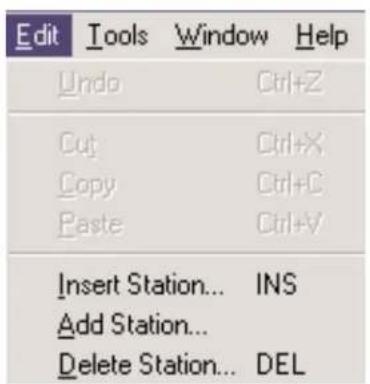
3.3.2. Edit Menu
text_image
Edit Undo Ctrl+Z Cut Ctrl+X Copy Ctrl+C Paste Ctrl+V Insert Station... INS Add Station... Delete Station... DELUndo
Not active at this time
Cut
Not active at this time
Copy
Not active at this time
Paste
Not active at this time
Insert Station
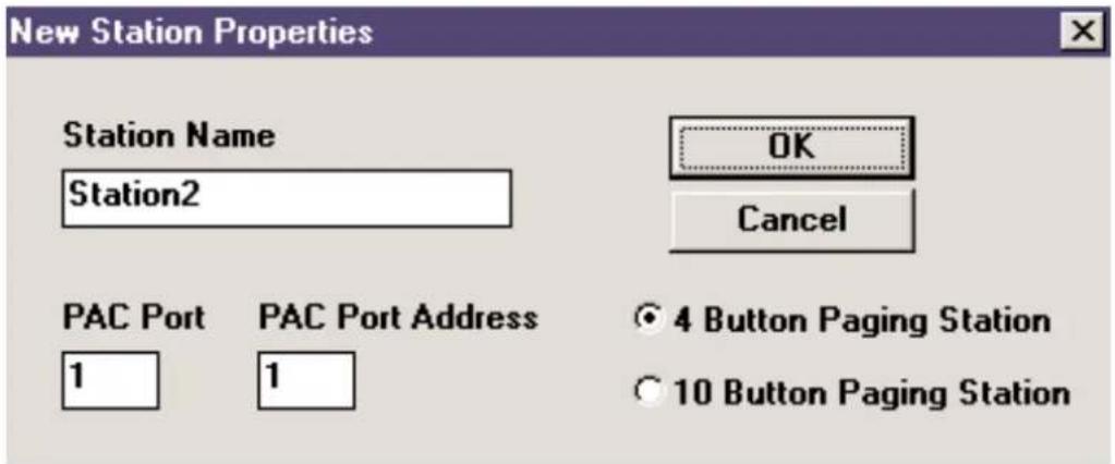
Creates a new paging station that is available for editing. It is placed in the list before the currently selected station. Selecting this option opens the “New Station Properties” dialog and allows the following edits:
Station Name: Up to 16 characters.
Number of buttons: 4 or 10.
PAC Port: Identifies the specific port (1-16) where the station is connected to the PageMatrix Controller.
PAC Port Address: Currently, always set to one.
text_image
New Station Properties Station Name Station2 OK Cancel PAC Port PAC Port Address 1 1 4 Button Paging Station 10 Button Paging StationAdd Station
Creates a new paging station that is available for editing. It is placed at the end of the list. Selecting this option opens the "New Station Properties" dialog and allows the following edits:
Station Name: Up to 16 characters.
Number of buttons: 4 or 10.
PAC Port: Identifies the specific port (1-16) where the station is connected to the PageMatrix controller.
PAC Port Address: Currently, always set to one.
Delete Station
Removes the currently selected station. The "Are You Sure" dialog opens for confirmation.
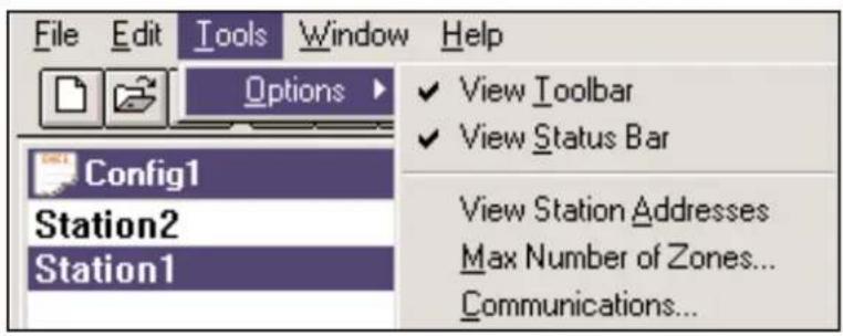
3.3.3. Tools Menu/Options
text_image
File Edit Tools Window Help Options View Toolbar View Status Bar Config1 View Station Addresses Station2 Max Number of Zones... Station1 Communications...View Toolbar
Show or hide the screen toolbar.
View Status Bar
Show or hide the status bar at the bottom of the window.
View Station Addresses
Displays the station address in front of the station name.
Max Number of Zones
Use this parameter to set the maximum number of zones used in your system.
Communications
Used to set the upload/download port. In addition to COM 1-4, an Offline Programming option is available when working remotely.
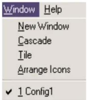
3.3.4. Window Menu
text_image
Window Help New Window Cascade Tile Arrange Icons ✓ 1 Config1New Window
Creates a new window.
Cascade
Standard Windows function that arranges all open configuration windows in a cascade pattern.
Tile
Standard Windows function that arranges all open configuration windows in a tile pattern.
Arrange Icons
Aligns minimized child windows.
Configuration Display
Lists all open configurations.
3.3.5. Help Menu
About PageMatrix
Displays the PageMatrix start-up screen.
| 4.0. Typical PageMatrix Operation
4.1. Overview
4.1.1. The components
PageMatrix / MediaMatrix paging systems consist of five primary components:
▲ At least one PageMatrix paging station connected to the PageMatrix controller via the proper category five cabling
▲ PageMatrix controller with the appropriate configuration file loaded
▲ PageMatrix application software
▲ A MediaMatrix audio system with PASHA running
▲ A proper PASHA.ini file configured for the "View File" compiled
4.1.2. Connections
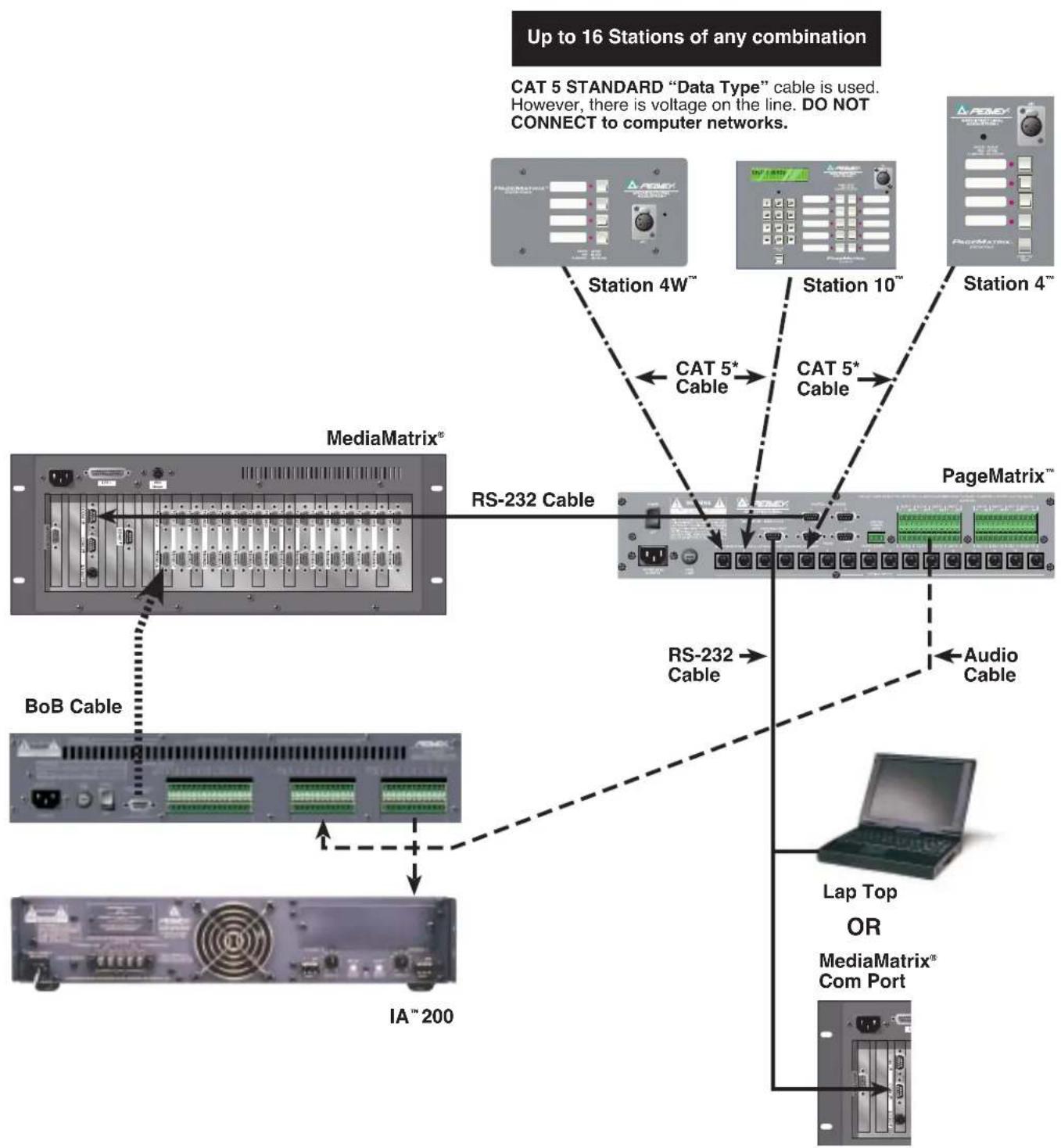
Paging stations connect to the PageMatrix controller via CAT 5 cabling. This cable carries three “signals”—the analog audio from the microphone, the voltage required to power the remote paging station, and the serial control data which will determine where the microphone’s audio signal will be routed by MediaMatrix.
The analog microphone signals from all paging stations are individually connected from their outputs on the rear of the PageMatrix Controller to the signal inputs of MediaMatrix break out boxes ("BoBs").
One of the serial outputs on the rear of the PageMatrix Controller connects to one of the Com Ports on the rear of the MediaMatrix frame.
4.1.3. The Desktop Paging Stations (Station Four and Station Ten)
There is no local switching of the “Push-to-Talk” microphone connected to the paging station. In all models the microphone is active or “on” at all times. Pressing station buttons results in activity of the serial communication to the PageMatrix Controller only.
4.1.4. The PageMatrix Controller
There are three functions of this device:
1: To provide power to the Paging stations.
2: To pass the analog microphone signals from the paging stations to the inputs of the MediaMatrix system's BoBs.
3: To interpret the proprietary control data from the paging stations and convert it to standard serial strings which can be forwarded to MediaMatrix.
Microphone signals from the paging stations are not acted upon by the PageMatrix Controller, but are simply passed through the box as received. Any switching or routing is done within MediaMatrix.
4.1.4. The MediaMatrix system and PASHA
Among many other tasks, the MediaMatrix system receives the analog audio from the Paging Stations via the PageMatrix controller, converts it to digital and performs all processing of those signals, including the routing of these signals to the various “zones”. These routing functions are accomplished by special PageMatrix devices within the system’s “View File” which are controlled from the PageMatrix Controller via PASHA.
4.1.5. Push-to-talk switch—What happens?
1: Pressing a station's zone preset button selects the configured zones in MediaMatrix.
2: When the push-to-talk switch is pressed, the PageMatrix Controller immediately sends the proper serial command to the MediaMatrix Com port. (The serial command sent is pre determined by the PageMatrix configuration file which has been downloaded and is running in the controller.)
3: This serial command is interpreted by MediaMatrix (via PASHA) and "presses" the appropriate router buttons in the MediaMatrix view file to send the audio to the zone or combination of zones selected by the paging station.
4: Audio passes to the zone(s) through MediaMatrix as long as the push-to-talk button on the station remains pressed.
5: Functions such as paging priorities, signal source ducking, zone equalization, etc. are all functions of the MediaMatrix system and are not directly acted upon by the PageMatrix components.
4.1.6. Operation within MediaMatrix
Paging devices can be complicated systems consisting of multiple “mixing routers.” For example, programming a paging device which consists of 8 stations and 32 buttons requires that a PASHA file be written addressing each of the matrix locations (256 parameters). Since programming your own Pasha files would require extensive time, we have provided a variety of view files and associated PASHA.INI files to simplify the task. We highly recommend you use the files we’ve provided on floppy disk and edit them for your specific application.
Basic Operation—Here we go...
- Find the appropriate .txt file for the device you wish to use.
- Rename this file to pasha.ini and place in the Peavey directory (mediamatrix\views).
Note: If you wish to keep the original pasha.ini file, just rename it.
- Open MediaMatrix (if not already launched).
- From the Device menu select "Paging" to view the available devices.
- Select an existing device and wire it accordingly.
- Test the routings and zones.
Example:
Suppose we want to use the 1632.pav file. Rename the 1632.txt file to pasha.ini.
Move this newly created pasha.ini to the MediaMatrix root directory.
4.2. Troubleshooting 101
▲ Remember, the view file must be compiled.
▲ Make sure Pasha.com(pasha.com1, pasha.com2, pasha.com3, or pasha.com4) is launched and matches the same com port used for PageMatrix.
▲ Be sure to launch PageMatrix and program a test file.
▲ In MediaMatrix, check the view file visual monitors to determine if the system is responding.
▲ Finally, check cable type, connection, and port settings.
5. APPENDIX
5.1. Factory Support
Peavey provides customer support and service direct from the factory. If you need further assistance or information, don't hesitate to call us. You can reach us 8 a.m. - 5 p.m. CST at (800) 543-2991 or (601) 483-5376. The address for correspondence/literature on current or new products is:
Peavey Electronics Corp. • MediaMatrix Support Group • 711 A St. • Meridian, MS 39301
You can also access helpful tips, specifications, FAQs, sample files, application notes and other Peavey Architectural Acoustics equipment product information 24 hours a day, seven days a week at our site on the World Wide Web. The URL is:
http://www.peavey.com/division/arch/index.html
In order to provide you with the best technical support, it will probably be necessary to see your view file so we can accurately diagnose your problem. This also helps to streamline your work and make your system more efficient. Using the Internet and e-mail, we can quickly get you up and running. Please direct your mail and attached view file to:
George Douglas, National Sales Manager george@peavey.com
Ken Valentine, Central District Manager ken@peavey.com
Will Roland, Western District Manager will@peavey.com
Joel Moak, Southeastern District Manager joel@peavey.com
Levin Culpepper, Internal Tech Support Coordinator levin@peavey.com
Brent Harshbarger, Product Manager brent@peavey.com
If you need emergency assistance after business hours or on the weekend, you may reach one of us on our SkyPager at (800) 759-7243. When you hear the prompt tone, enter the PIN 113-4326. Please reserve this for true MediaMatrix emergencies or weekend use.
ARCHITECTURALACOUSTICS®
711 A Street • Meridian, MS 39301
(601) 483-5376 • FAX (601) 486-1678
http://www.peavey.com • ©1998
Features and specifications are subject to change without notice.
5.2. Using the MediaMatrix Program Launcher
text_image
MediaMatrix - [noname0.pav] File Edit Device Mode Tools User Window Help Again AmpWare (TM) Automatic Mixer Crossover Delay Diagnostics Distribution Amp Dynamics Equalizer Input/Output Level Meter Miscellaneous Dither Mixer Error Indicator New Hardware Failure Indicator Preset Hardware Key Processors Program Launcher RoomLink (TM) Signal Probe Router System Mute Test Via Libraries Ready Local(Idle)The Program Launcher is found in the Device/Miscellaneous Menu. It is used to make it easy to open another Windows application while you are using MediaMatrix. You can label the Program Launcher block and include it in any window of a MediaMatrix design. The Program Launcher device can either launch another Windows™ application or switch to that application if it is already running. The Object Properties dialog for this object has a field titled “Run this program” that contains the complete path and file name and optional command line arguments of the program you want to run. You can browse the applications that are currently running by pressing the “Window Title...” button, and you can browse for executables (*.exe) by pressing the “File Name...” button. The object can perform its action, either running or switching to the other application, on either a single mouse click or on a double-click as determined by the settings of the “Run program on” radio buttons. In Edit Mode, the action is always on a double-click.
text_image
PAGEMATRIX™ STATION FOUR-W PEAVY® ARCHITECTURAL ACQUSTICS® MIO GREEN - READY RED - IN USE FLASHING - SELECTEDCat 5 Plug 4-Pin Connector
1 485+
2 485
3 GND
4 24V+
5 GND
Cat 5 Plug 3-Pin Connector
6 GND
7 ← Line Out
8 Line Out
text_image
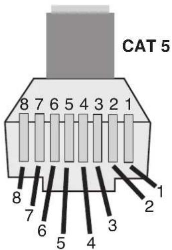
CAT 5 8 7 6 5 4 3 2 1 8 7 6 5 4 3 2 1NOTE: This is not a network connection.
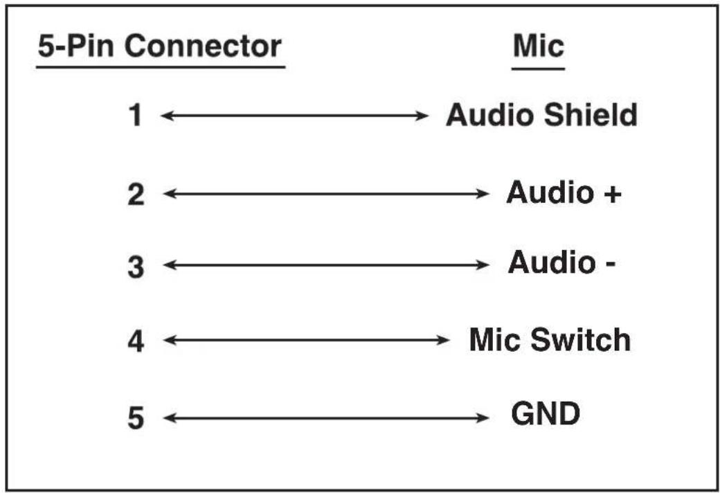
5.4. 5-Pin Wiring Diagram
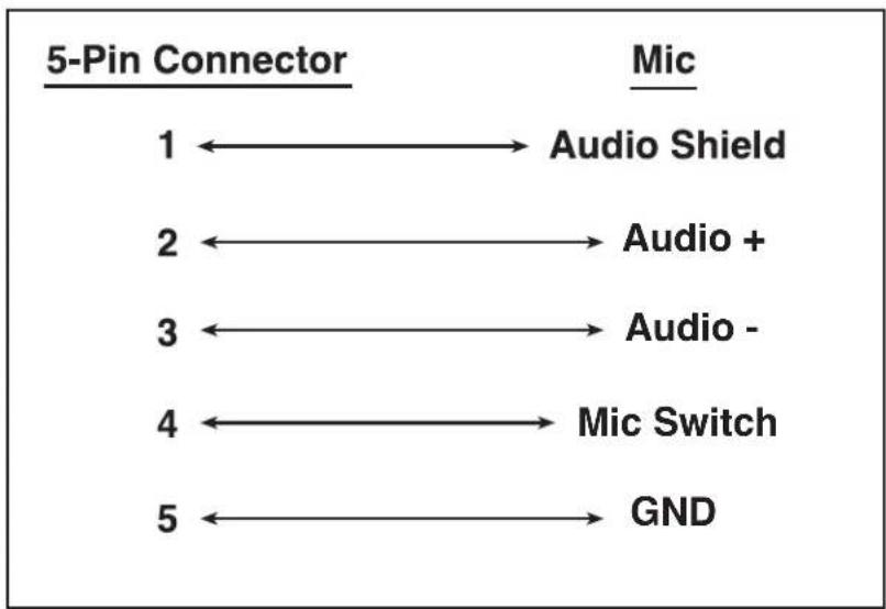
flowchart
graph LR
    A["1"] --> B["Audio Shield"]
    C["2"] <--_D["Audio +"]
    E["3"] <--_F["Audio -"]
    G["4"] <--_H["Mic Switch"]
    I["5"] <--_J["GND"]
5.5. Configuring the PageMatrix Controller
As mentioned previously, the PageMatrix controller supports up to sixteen paging stations simultaneously. In larger applications where multiple controllers are necessary, the various PageMatrix units must be configured for IDs beyond the default 1-16 setting. This is accomplished by changing the DIP switch settings inside the unit.
- Remove top plate of the controller (six screws).
- Now viewing the inside of the unit, find the DIP switch (labeled SW100) located at the front left side of the unit.
- You will only adjust switches 1 and 2 according to the chart below.
- Switches 3 through 8 are inactive.
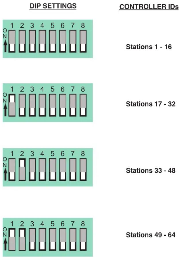
bar
| Station ID | DIP SETTINGS | CONTROLLER IDs | | ---------------- | ------------ | -------------- | | Stations 1 - 16 | 1 | 16 | | Stations 17 - 32 | 1 | 32 | | Stations 33 - 48 | 1 | 48 | | Stations 49 - 64 | 1 | 64 |NOTE: Factory settings default to 1-16
5.6. Specifications
PageMatrix Controller
Power Requirements:
Domestic: 120V AC\~, 60 Hz, 50W
Export: 100V AC\~, 50/60 Hz, 50W
230V AC\~, 50/60 Hz, 50W
Included Accessories:
IEC Line Cord
(4) 12 position Phoenix-type connectors
(1) 3 position Phoenix-type connector
Dimensions and Weight:
3.5" H x 19" W x 11.69" D
(excluding connectors)
13.7 lbs.
Category 5 cable length
Maximum 1,000 ft
Note: Standard "data type" cable is used; however, there is voltage on the line.
DO NOT connect to computer networks.
Station Four-W Mounting
Station 4-W Wallmount does not come with a back panel. It is recommended to use a standard 4 Gang Electrical box with these dimensions: 3.75" H x 7.5" W x 2.0" (Min) D.
Paging Stations
Maximum Input Level:
Station 4 Wallmount: -22 dBu
Station 4 Desktop: -22 dBu
Station 10 Desktop: -22 dBu
Maximum Output Level:
Station 4 Wallmount: +25 dBu
Station 4 Desktop: +25 dBu
Station 10 Desktop: +25 dBu
Input Impedance:
Station 4 Wallmount: 2.2K ohms
Station 4 Desktop: 2.2K ohms
Station 10 Desktop: 2.2K ohm
Output Impedance:
Station 4W Wallmount: 200 ohms
Station 4 Desktop: 200 ohms
Station 10 Desktop: 200 ohms
Frequency Response:
Station 4 Wallmount: 20Hz to 20 kHz (+0, -2 dB)
Station 4 Desktop: 20Hz to 20 kHz (+0, -2 dB)
Station 10 Desktop: 20Hz to 20 kHz (+0, -2 dB)
Total Harmonic Distortion:
Station 4 Wallmount: Less than 0.01% at 1 kHz
Station 4 Desktop: Less than 0.01% at 1 kHz
Station 10 Desktop: Less than 0.01% at 1 kHz
Signal-to-Noise Ratio:
Station 4 Wallmount: Greater than 88 dB
Station 4 Desktop: Greater than 85 dB
Station 10 Desktop: Greater than 84 dB
Phantom Power:
Station 4 Wallmount: +48V DC
Station 4 Desktop: +48V DC
Station 10 Desktop: +48V DC
Power Requirements:
Station 4 Wallmount: 48mA at +24V DC
Station 4 Desktop: 55mA at +24V DC
Station 10 Desktop: 92mA at +24V DC
Dimensions:
Station 4 Wallmount: 4.5" H x 8.2" W x 1" D
Station 4 Desktop: 4.0" H x 5.2" W x 7.1" D
Station 10 Desktop: 4.0" H x 10.4" W x 7.1" D
ESPAÑOL
1. Introducción
2.4. Typical PageMatrix Connection
flowchart
graph TD
    A["MediaMatrix®"] -->|RS-232 Cable| B["RS-232 Cable"]
    A -->|Audio Cable| C["PageMatrix™"]
    D["BoB Cable"] --> A
    E["IA™ 200"] --> A
    F["Up to 16 Stations of any combination"] --> G["Station 4W™"]
    F --> H["Station 10™"]
    F --> I["Station 4™"]
    G <--> J["CAT 5* Cable"]
    H <--> K["CAT 5* Cable"]
    I <--> L["Cat 5* Cable"]
    M["Lap Top OR MediaMatrix® Com Port"] --> N["Audio Cable"]
    style A fill:#f9f,stroke:#333
    style B fill:#ccf,stroke:#333
    style C fill:#cfc,stroke:#333
    style D fill:#fcc,stroke:#333
    style E fill:#cff,stroke:#333
    style F fill:#ffc,stroke:#333
    style G fill:#fcf,stroke:#333
    style H fill:#fcf,stroke:#333
    style I fill:#fcf,stroke:#333
    style J fill:#cff,stroke:#333
    style K fill:#cff,stroke:#333
    style L fill:#ffc,stroke:#333
    style M fill:#fcc,stroke:#333
3. Descripción del software PageMatrix
text_image
Peavey PageMatrix - Config1 File Edit Tools Window Help Config1 Station1 Zone Name: Zone1 Station2 HB-01 HB-02 HB-03 HB-04 For Help, press F1 NUMtext_image
File Edit Tools Window Help New Ctrl+N Open... Ctrl+O Close Save Ctrl+S Save As... Print... Ctrl+P Print Preview Print Setup... Download Config... 1 TEST.PMX ExitNew (nuevo)
text_image
Edit Undo Ctrl+Z Cut Ctrl+X Copy Ctrl+C Paste Ctrl+V Insert Station... INS Add Station... Delete Station... DEL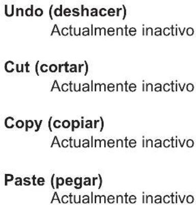
text_image
New Station Properties Station Name Station2 OK Cancel PAC Port PAC Port Address 1 1 4 Button Paging Station 10 Button Paging Stationtext_image
File Edit Tools Window Help Options View Toolbar View Status Bar Config1 Station2 Station1 View Station Addresses Max Number of Zones... Communications...View Toolbar (ver barra de herramientas)
http://www.peavey.com/division/arch/index.html
5.3. Station 4-W Wiring Diagram
text_image
PAGEMATRIX™ STATION FOUR-W FENVEY® ARCHITECTURAL ACQUETICS® MIC GREEN - READY RED - IN USE FLASHING - SELECTEDCat 5 Plug 4-Pin Connector
1 485+
2 485
3 GND
4 24V+
5 GND
Cat 5 Plug 3-Pin Connector
6 GND
7 ← Line Out
8 Line Out
text_image
CAT 5 8 7 6 5 4 3 2 1 8 7 6 5 4 3 2 1 1 2 3 4 5NOTE: This is not a network connection.
5-Pin Connector
Mic
1 ← Audio Shield
2 ← Audio +
3 ← Audio -
4 Mic Switch
5 GND
2.4. Typical PageMatrix Connection
flowchart
graph TD
    A["MediaMatrix®"] -->|RS-232 Cable| B["RS-232 Cable"]
    A -->|Audio Cable| C["PageMatrix™"]
    D["BoB Cable"] --> A
    E["IA™ 200"] --> A
    F["Station 4W™"] -->|CAT 5* Cable| B
    G["Station 10™"] -->|CAT 5* Cable| B
    H["Lap Top OR MediaMatrix® Com Port"] -->|Audio Cable| C
    I["Up to 16 Stations of any combination"] --> J["Station 4W™"]
    I --> K["Station 10™"]
    I --> L["Station 4™"]
| Edit | Tools | Window | Help |
| Undo | Ctrl+Z | ||
| Cut | Ctrl+X | ||
| Copy | Ctrl+C | ||
| Paste | Ctrl+V | ||
| Insert Station... | INS | ||
| Add Station... | |||
| Delete Station... | DEL | ||
Undo (Annuler)
Option non activée.
Cut (Découper)
Option non activée.
Copy (Copier)
Option non activée.
Paste (Coller)
Option non activée.
Insert Station (Insérer Poste)
text_image
New Station Properties Station Name Station2 OK Cancel PAC Port PAC Port Address 1 1 4 Button Paging Station 10 Button Paging StationAdd Station (ajouter poste)
text_image
File Edit Tools Window Help Options View Toolbar View Status Bar Config1 Station2 Station1 View Station Addresses Max Number of Zones... Communications...Tile (Juxtaposition)
http://www.peavey.com/division/arch/index.html
5.3. Station 4-W Wiring Diagram
text_image
PAGEMATRIX™ STATION FOUR-W PEAVEY® ARCHITECTURAL ACQUOSTICS® MIC GREEN - READY RED - IN USE FLASHING - SELECTEDCat 5 Plug 4-Pin Connector
1 485+
2 485 -
3 GND
4 24V+
5 GND
Cat 5 Plug 3-Pin Connector
6 GND
7 ← Line Out
8 Line Out
text_image
CAT 5 8 7 6 5 4 3 2 1 8 7 6 5 4 3 2 1 1 2NOTE: This is not a network connection.
5.4. 5-Pin Wiring Diagram
flowchart
graph LR
    A["1"] --> B["Audio Shield"]
    C["2"] --> D["Audio +"]
    E["3"] --> F["Audio -"]
    G["4"] --> H["Mic Switch"]
    I["5"] <--_J["GND"]
Exportation: 100 V c.a\~, 50/60 Hz, 50 W
230 V c.a.\~, 50/60 Hz, 50 W
Accessoires inclus:
CONSERVEZ CES INSTRUCTIONS!
DEUTSCH
1. Einleitung
2.4. Typical PageMatrix Connection
flowchart
graph TD
    A["MediaMatrix®"] -->|RS-232 Cable| B["Station 4W™"]
    A -->|RS-232 Cable| C["Station 10™"]
    A -->|RS-232 Cable| D["PageMatrix™"]
    A -->|Audio Cable| E["Lap Top OR MediaMatrix® Com Port"]
    A -->|BoB Cable| F["IA™ 200"]
    B -->|CAT 5* Cable| C
    C -->|CAT 5* Cable| D
    style A fill:#f9f,stroke:#333
    style B fill:#ccf,stroke:#333
    style C fill:#ccf,stroke:#333
    style D fill:#ccf,stroke:#333
    style E fill:#dfd,stroke:#333
    note right of A: 'Up to 16 Stations of any combination'
    note right of B: 'CAT 5 STANDARD "Data Type" cable is used. However, there is voltage on the line. DO NOT CONNECT to computer networks.'
text_image
Edit Tools Window Help Undo Ctrl+Z Cut Ctrl+X Copy Ctrl+C Paste Ctrl+V Insert Station... INS Add Station... Delete Station... DELUndo (Rückgängig)
text_image
New Station Properties Station Name Station2 OK Cancel PAC Port PAC Port Address 1 1 4 Button Paging Station 10 Button Paging Stationtext_image
File Edit Tools Window Help Options View Toolbar View Status Bar Config1 View Station Addresses Station2 Max Number of Zones... Station1 Communications...Cascade (Überlappen)
http://www.peavey.com/division/arch/index.html
George Douglas, National Sales Manager george@peavey.com
Ken Valentine, Central District Manager ken@peavey.com
Will Roland, Western District Manager will@peavey.com
Joel Moak, Southeastern District Manager joel@peavey.com
Levin Culpepper, Internal Tech Support Coordinator levin@peavey.com
Brent Harshbarger, Product Manager brent@peavey.com
5.3. Station 4-W Wiring Diagram
text_image
PAGEMATRIX™ STATION FOUR-W PEAVY® ARCHITECTURAL ACOUSTICS® MIC GREEN - READY RED - IN USE FLASHING - SELECTEDCat 5 Plug 4-Pin Connector
1 485+
2 485
3 GND
4 24V+
5 GND
Cat 5 Plug 3-Pin Connector
6 GND
7 ← Line Out
8 Line Out
text_image
CAT 5 8 7 6 5 4 3 2 1 8 7 6 5 4 3 2 1 1 2 3 4 5NOTE: This is not a network connection.
5.4. 5-Pin Wiring Diagram
flowchart
graph LR
    A["5-Pin Connector"] --> B["1"]
    B --> C["Audio Shield"]
    A --> D["2"]
    D --> E["Audio +"]
    A --> F["3"]
    F --> G["Audio -"]
    A --> H["4"]
    H --> I["Mic Switch"]
    A --> J["5"]
    J --> K["GND"]
    style A fill:#f9f,stroke:#333
    style B fill:#ccf,stroke:#333
    style C fill:#cfc,stroke:#333
    style D fill:#fcc,stroke:#333
    style E fill:#cff,stroke:#333
    style F fill:#ffc,stroke:#333
    style G fill:#cfc,stroke:#333
    style H fill:#fcc,stroke:#333
    style I fill:#cfc,stroke:#333
    style J fill:#fcc,stroke:#333
    style K fill:#cfc,stroke:#333
Station 4 (Wandmontage): -22 dBu
Station 4 (Wandmontage): +25 dBu
Station 4 (Wandmontage): 2,2 kΩ
Station 4W (Wandmontage): 200 Ω
Station 4 (Wandmontage): +48 V=
Station 4 (Wandmontage): 114 mm x 208 mm x 25 mm (H x B x T)
IMPORTANT SAFETY INSTRUCTIONS
WARNING: When using electric products, basic cautions should always be followed, including the following:
-
Read these instructions.
-
Keep these instructions.
-
Heed all warnings.
-
Follow all instructions.
-
Do not use this apparatus near water. For example, near or in a bathtub, swimming pool, sink, wet basement, etc.
-
Clean only with a damp cloth.
-
Do not block any of the ventilation openings. Install in accordance with manufacturer's instructions. It should not be placed flat against a wall or placed in a built-in enclosure that will impede the flow of cooling air.
-
Do not install near any heat sources such as radiators, heat registers, stoves or other apparatus (including amplifiers) that produce heat.
-
Do not defeat the safety purpose of the polarized or grounding-type plug. A polarized plug has two blades with one wider than the other. A grounding type plug has two blades and a third grounding plug. The wide blade or third prong is provided for your safety. When the provided plug does not fit into your inlet, consult an electrician for replacement of the obsolete outlet. Never break off the grounding write for our free booklet "Shock Hazard and Grounding". Connect only to a power supply of the type marked on the unit adjacent to the power supply cord.
-
Protect the power cord from being walked on or pinched particularly at plugs, convenience receptacles, and the point they exit from the apparatus.
-
Only use attachments/accessories provided by the manufacturer.
-
Use only with a cart, stand, tripod, bracket, or table specified by the manufacturer, or sold with the apparatus. When a cart is used, use caution when moving the cart/apparatus combination to avoid injury from tip-over.
-
Unplug this apparatus during lightning storms or when unused for long periods of time.
-
Refer all servicing to qualified service personnel. Servicing is required when the apparatus has been damaged in any way, such as power-supply cord or plug is damaged, liquid has been spilled or objects have fallen into the apparatus, the apparatus has been exposed to rain or moisture, does not operate normally, or has been dropped..
-
If this product is to be mounted in an equipment rack, rear support should be provided.
-
Exposure to extremely high noise levels may cause a permanent hearing loss. Individuals vary considerably in susceptibility to noise induced hearing loss, but nearly everyone will lose some hearing if exposed to sufficiently intense noise for a sufficient time. The U.S. Government's Occupational and Health Administration (OSHA) has specified the following permissible noise level exposures:.
| Duration Per Day In Hours Sound Level dBA, Slow Response | |
| 8 | 90 |
| 6 | 92 |
| 4 | 95 |
| 3 | 97 |
| 2 100 | |
| 1 1/2 102 | |
| 1 105 | |
| 1/2 110 | |
| 1/4 or less 115 | |
According to OSHA, any exposure in excess of the above permissible limits could result in some hearing loss. Ear plugs or protectors to the ear canals or over the ears must be worn when operating this amplification system in order to prevent a permanent hearing loss if exposure is in excess of the limits as set forth above. To ensure against potentially dangerous exposure to high sound pressure levels, it is recommended that all persons exposed to equipment capable of producing high sound pressure levels such as this amplification system be protected by hearing protectors while this unit is in operation.
SAVE THESE INSTRUCTIONS!
PEAVEY ELECTRONICS CORPORATION LIMITED WARRANTY
Effective Date: July 1, 1998
What This Warranty Covers
Your Peavey Warranty covers defects in material and workmanship in Peavey products purchased and serviced in the U.S.A. and Canada.
What This Warranty Does Not Cover
The Warranty does not cover: (1) damage caused by accident, misuse, abuse, improper installation or operation, rental, product modification or neglect; (2) damage occurring during shipment; (3) damage caused by repair or service performed by persons not authorized by Peavey; (4) products on which the serial number has been altered, defaced or removed; (5) products not purchased from an Authorized Peavey Dealer.
Who This Warranty Protects
This Warranty protects only the original retail purchaser of the product.
How Long This Warranty Lasts
The Warranty begins on the date of purchase by the original retail purchaser. The duration of the Warranty is as follows:
Product Category Duration
| Guitars/Basses, Amplifiers, Pre-Amplifiers, Mixers, Electronic Crossovers and Equalizers 2 years *(+ 3 years) | |
| Drums 2 years *(+ 1 year) | |
| Enclosures 3 years *(+ 2 years) | |
| Digital Effect Devices and Keyboard and MIDI Controllers 1 year *(+ 1 year) | |
| Microphones 2 years | |
| Speaker Components (incl. speakers, baskets, drivers, diaphragm replacement kits and passive crossovers) and all Accessories 1 year | |
| Tubes and Meters 90 days |
[*denotes additional warranty period applicable if optional Warranty Registration Card is completed and returned to Peavey by original retail purchaser within 90 days of purchase.]
What Peavey Will Do
We will repair or replace (at Peavey's discretion) products covered by warranty at no charge for labor or materials. If the product or component must be shipped to Peavey for warranty service, the consumer must pay initial shipping charges. If the repairs are covered by warranty, Peavey will pay the return shipping charges.
How To Get Warranty Service
(1) Take the defective item and your sales receipt or other proof of date of purchase to your Authorized Peavey Dealer or Authorized Peavey Service Center.
OR
(2) Ship the defective item, prepaid, to Peavey Electronics Corporation, International Service Center, 412 Highway 11 & 80 East, Meridian, MS 39301 or Peavey Canada Ltd., 95 Shields Court, Markham, Ontario, Canada L3R 9T5. Include a detailed description of the problem, together with a copy of your sales receipt or other proof of date of purchase as evidence of warranty coverage. Also provide a complete return address.
Limitation of Implied Warranties
ANY IMPLIED WARRANTIES, INCLUDING WARRANTIES OF MERCHANTABILITY AND FITNESS FOR A PARTICULAR PURPOSE, ARE LIMITED IN DURATION TO THE LENGTH OF THIS WARRANTY.
Some states do not allow limitations on how long an implied warranty lasts, so the above limitation may not apply to you.
Exclusions of Damages
PEAVEY'S LIABILITY FOR ANY DEFECTIVE PRODUCT IS LIMITED TO THE REPAIR OR REPLACEMENT OF THE PRODUCT, AT PEAVEY'S OPTION. IF WE ELECT TO REPLACE THE PRODUCT, THE REPLACEMENT MAY BE A RECONDITIONED UNIT. PEAVEY SHALL NOT BE LIABLE FOR DAMAGES BASED ON INCONVENIENCE, LOSS OF USE, LOST PROFITS, LOST SAVINGS, DAMAGE TO ANY OTHER EQUIPMENT OR OTHER ITEMS AT THE SITE OF USE, OR ANY OTHER DAMAGES WHETHER INCIDENTAL, CONSEQUENTIAL OR OTHERWISE, EVEN IF PEAVEY HAS BEEN ADVISED OF THE POSSIBILITY OF SUCH DAMAGES
Some states do not allow the exclusion or limitation of incidental or consequential damages, so the above limitation or exclusion may not apply to you.
This Warranty gives you specific legal rights, and you may also have other rights which vary from state to state.
If you have any questions about this warranty or service received or if you need assistance in locating an Authorized Service Center, please contact the Peavey International Service Center at (601) 483-5365 / Peavey Canada Ltd. at (905) 475-2578.
Features and specifications subject to change without notice.

PEAVEY®
Features and specifications subject to change without notice.
Peavey Electronics Corporations • 711 A Street • Meridian, MS 39301 • U.S.A.
(601) 483-5367 • Fax (601) 486-1678 • www.peavey.com