ProGYS 160 LA - Welding machine GYS - Free user manual and instructions
Find the device manual for free ProGYS 160 LA GYS in PDF.
User questions about ProGYS 160 LA GYS
0 question about this device. Answer the ones you know or ask your own.
Ask a new question about this device
Download the instructions for your Welding machine in PDF format for free! Find your manual ProGYS 160 LA - GYS and take your electronic device back in hand. On this page are published all the documents necessary for the use of your device. ProGYS 160 LA by GYS.
USER MANUAL ProGYS 160 LA GYS
natural_image
Line drawing of a portable electrical heating unit with ventilation slots and control knobs (no text or symbols)FR 02-08 / 65-72
EN 09-15 / 65-72
DE 16-22 / 65-72
ES 23-29 / 65-72
RU 30-36 / 65-72
NL 37-43 / 65-72
IT 44-50 / 65-72
PL 51-57 / 65-72
CZ 58-64 / 65-72
PROGYS 160LA
Poste à souder MMA et TIG Lift MMA (SMAW) and TIG (GTAW) welding machine Schweissgerät für E-Hand (MMA) und WIG Lift Equipo de soldadura MMA y TIG Lift Сварочный аппарат MMA и ТИГ Lift MMA en TIG Lift lasapparaat Dispositivo saldatura MMA e TIG Lift Stanowisko do spawania MMA i TIG Lift

AVERTISSEMENTS - RÈGLES DE SÉCURITÉ
CONSIGNE GÉNÉRALE

INSTALLATION – FONCTIONNEMENT PRODUIT
Read and understand the following safety instructions before use.
Any modification and maintenance not specified in the instructions manual should not be undertaken.
The manufacturer is not liable for any injury or damage due to non-compliance with the instructions featured in this manual.
In the event of problems or uncertainties, please consult a qualified person to handle the installation properly.
ENVIRONMENT
This equipment must only be used for welding operations in accordance with the limits indicated on the descriptive panel and/or in the user manual. Safety instructions must be followed. In case of improper or unsafe use, the manufacturer cannot be held liable.
This equipment must be used and stored in a room free from dust, acid, flammable gas or any other corrosive agent. Operate the machine in an open, or well-ventilated area.
Operating temperature:
Use between -10 and +40°C (+14 and +104°F).
Storage between -20 and +55°C (-4 and 131°F).
Air humidity:
Lower or equal to 50% at 40°C (104°F).
Lower or equal to 90% at 20°C (68°F).
Altitude:
Up to 1000 meters above sea level (3280 feet).
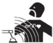
INDIVIDUAL PROTECTION AND PROTECTION FOR OTHERS
Arc welding can be dangerous and can cause serious injury or even death.
Welding exposes the user to dangerous heat, arc rays, electromagnetic fields, risk of electric shock, noise and gas fumes. People wearing pacemakers are advised to consult a doctor before using the welding machine.
To protect oneself as well others, ensure the following safety precautions are taken:

In order to protect yourself from burns and radiation, wear clothing without turn-up or cuffs. These clothes must be insulated, dry, fireproof, in good condition and cover the whole body.

Wear protective gloves to guarantee electrical and thermal insulation.

Wear sufficient welding protective gear for the whole body: hood, gloves, jacket, trousers... (varies depending on the application/operation). Protect the eyes during cleaning operations. Contact lenses are prohibited during use.
It may be necessary to install fireproof welding curtains to protect the area against arc rays, weld spat-ter and sparks.
Inform the people around the working area to never look at the arc nor the molten metal, and to wear protective clothes.

Ensure ear protection is worn by the operator if the work exceeds the authorised noise limit (the same applies to any person in the welding area).
Keep hands, hair and clothes away from moving parts such as fans, and engines.
Never remove the safety covers from the cooling unit when the machine is plugged in. The manufacturer is not liable for any injury or damage caused due to non-compliance with the safety precautions.
Parts that have previously been welded will be hot and may cause burns if manipulated. During maintenance work on the torch or the electrode holder, you should make sure it's cold enough and wait at least 10 minutes before any intervention. When using a water-cooled torch, make sure that the cooling unit is switched on to avoid any burns that could potentially be caused by the liquid. It is important to secure the working area before leaving to ensure the protection of property and the safety of others.
WELDING FUMES AND GAS

Fumes, gas and dust produced during welding are hazardous to health. It is mandatory to ensure adequate ventilation and/or extraction to keep fumes and gas away from the work area. Using an air fed welding helmet is recommended in case of insufficient ventilation in the workplace.
Check that the air supply is effective by referring to the recommended safety regulations.
Precautions must be taken when welding in small areas, and the operator will need supervision from a safe distance. Welding certain pieces of metal containing lead, cadmium, zinc, mercury or beryllium can be extremely toxic. The user will also need to degrease the workpiece before welding.
Gas cylinders must be stored in an open or ventilated area. They must be stored vertically and held by a support or trolley to limit the risk of falling. Do not weld in areas where grease or paint are stored.
FIRE AND EXPLOSION HAZARDS
Protect the entire welding area. Flammable materials must be moved to a minimum safe distance of 11 meters.
A fire extinguisher must be readily available near the welding operations.
Be careful of weld spatter and sparks, even through cracks. If not careful then this could potentially lead to a fire or an explosion.
Keep people, flammable materials/objects and containers that are under pressure at a safe distance.
Welding in closed containers or pipes should be avoided and, if they are opened, they must be emptied of any flammable or explosive material (oil, fuel, gas ...).
Grinding operations should not be carried out close to the power supply or any flammable materials.
GAS CYLINDERS

Gas leaking from the cylinders can lead to suffocation if present in high concentration around the work area (ventilation required).
Transport must be done safely: cylinders closed and welding machine switched off. They must be stored vertically and held by a support to limit the risk of falling.
Close the cylinder between two uses. Beware of temperature variations and sun exposure.
The cylinder must not be in contact with a flame, electric arc, torch, earth clamp or all other sources of heat.
Always keep gas cylinders away from electrical circuits, and therefore never weld a cylinder under pressure.
Be careful when opening the valve on the gas bottle, it is necessary to remove the tip of the valve and make sure the gas meets your welding requirements.
ELECTRICAL SAFETY

The electrical mains used must have an earth terminal. Use the recommended fuse size.
An electric shock could cause serious injuries or potentially even deadly accidents.
Do not touch any live part of the machine (inside or outside) when it is plugged in (Torches, earth cable, cables, electrodes) because they are connected to the welding circuit.
Before opening the device, it is imperative to disconnect it from the mains and wait 2 minutes, so that all the capacitors are discharged.
Do not touch the torch or electrode holder and the earth clamp at the same time.
Damaged cables and torches must be changed by a qualified and skilled professional. Make sure that the cable cross section is adequate with the usage (extensions and welding cables). Always wear dry clothes which are in good condition in order to be isolated from the welding circuit. Wear insulated shoes, regardless of the workplace/environment in which you work in.
EMC CLASSIFICATION

This Class A machine is not intended to be used on a residential site where the electric current is supplied by the domestic low-voltage power grid. There may be potential difficulties in ensuring electromagnetic compatibility at these sites, due to conducted interferences as well as radiation.
Provided that the impedance of the low-voltage public electrical network at the common coupling point is less than Zmax = 0.427 Ohms, this equipment complies with IEC 61000-3-11 and can be connected to public low-voltage electrical mains. It is the responsibility of the installer or user of the equipment to ensure, in consultation with the distribution network operator if necessary, that the network impedance complies with the impedance restrictions.
This equipment does not comply with IEC 61000-3-12 and is intended to be connected to private low-voltage systems interfacing with the public supply only at the medium- or high-voltage level. On a public low-voltage power grid, it is the responsibility of the installer or user of the device to ensure, by checking with the operator of the distribution network, which device can be connected.
ELECTROMAGNETIC EMISSIONS
The electric current flowing through any conductor causes electrical and magnetic fields (EMF). The welding current generates an EMF around the welding circuit and the welding equipment.
The EMF electromagnetic fields can interfere with certain medical implants, such as pacemakers. Protection measures must be taken for people with medical implants. For example, by restricting access to passers-by or conducting an individual risk evaluation for the welders.
All welders should take the following precautions in order to minimise exposure to the electromagnetic fields (EMF) generated by the welding circuit:
- position the welding cables together – if possible, attach them;
- keep your head and torso as far as possible from the welding circuit;
- never wrap the cables around your body;
- never position your body between the welding cables. Hold both welding cables on the same side of your body;
- connect the earth clamp as close as possible to the area being welded;
- do not work too close, do not lean and do not sit on the welding machine
- do not weld when you're carrying the welding machine or its wire feeder.

People wearing pacemakers are advised to consult their doctor before using this device.
Exposure to electromagnetic fields while welding may have other health effects which are not yet identified.
RECOMMENDATIONS TO ASSESS THE WELDING AREA AND WELDING INSTALLATION
Overview
The user is responsible for the installation and use of the arc welding equipment according to the manufacturer's instructions. If electromagnetic disturbances are detected, the user is responsible for resolving the situation with the manufacturer's technical assistance. In some cases, this corrective action may be as simple as earthing the welding circuit. In other cases, it may be necessary to construct an electromagnetic shield around the welding power source and around the entire piece by fitting input filters. In all cases, electromagnetic interferences must be reduced until they are no longer inconvenient.
Welding area assessment
Before installing the machine, the user must evaluate the possible electromagnetic problems that may arise in the area where the installation is planned. The following elements should be taken into account:
a) the presence (above, below and next to the arc welding machine) of other power cables, remote cables and telephone cables;
b) television transmitters and receivers;
c) computers and other hardware;
d) critical safety equipment such as industrial machine protections;
e) the health and safety of the people in the area such as people with pacemakers or hearing aids;
f) calibration and measuring equipment;
g) the isolation of other pieces of equipment which are in the same area.
The user has to ensure that the devices and pieces of equipment used in the same area are compatible with each other. This may require extra precautions;
h) the time of day during the welding or other activities have to be performed.
The surface of the area to be considered around the device depends on the building's structure and other activities that take place there. The area taken into consideration can be larger than the limits of the installations.
Welding area assessment
Besides the welding area, the assessment of the arc welding systems installation itself can be used to identify and resolve cases of disturbances. The assessment of emissions must include in situ measurements as specified in Article 10 of CISPR 11. In situ measurements can also be used to confirm the effectiveness of mitigation measures.
RECOMMENDATION ON METHODS OF ELECTROMAGNETIC EMISSIONS REDUCTION
a. National power grid: the arc welding machine must be connected to the national power grid in accordance with the manufacturer's recommendation. In case of interferences, it may be necessary to take additional precautions such as the filtering of the power supply network. Consideration should be given to shielding the power supply cable in a metal conduit or equivalent of permanently installed arc welding equipment. It is necessary to ensure the electrical continuity of the shielding along its entire length. The shielding should be connected to the welding current's source to ensure good electrical contact between the conduct and the casing of the welding current source.
b. Maintenance of the arc welding equipment: The arc welding machine should be subject to a routine maintenance check according to the recommendations of the manufacturer. All accesses, service doors and covers should be closed and properly locked when the arc welding equipment is on. The arc welding equipment must not be modified in any way, except for the changes and settings outlined in the manufacturer's instructions. The spark gap of the arc start and arc stabilization devices must be adjusted and maintained according to the manufacturer's recommendations.
c. Welding cables: Cables must be as short as possible, close to each other and close to the ground, if not on the ground.
d. Equipotential bonding: consideration should be given to bonding all metal objects in the surrounding area. However, metal objects connected to the workpiece increase the risk of electric shock if the operator touches both these metal elements and the electrode. It is necessary to insulate the operator from such metal objects.
e. Earthing of the welded part: When the part is not earthed - due to electrical safety reasons or because of its size and its location (which is the case with ship hulls or metallic building structures), the earthing of the part can, in some cases but not systematically, reduce emissions It is preferable to avoid the earthing of parts that could increase the risk of injury to the users or damage other electrical equipment. If necessary, it is appropriate that the earthing of the part is done directly, but in some countries that do not allow such a direct connection, it is appropriate that the connection is made with a capacitor selected according to national regulations.
f. Protection and shielding: The selective protection and shielding of other cables and devices in the area can reduce perturbation issues. The protection of the entire welding area can be considered for specific situations.
TRANSPORT AND TRANSIT OF THE WELDING MACHINE

The machine is fitted with handle to facilitate transportation. Be careful not to underestimate the machine's weight. The handle cannot be used for slinging.
Do not use the cables or torch to move the machine. The welding equipment must be moved in an upright position.
Do not place/carry the unit over people or objects.
Never lift the machine while there is a gas cylinder on the support shelf. A clear path is available when moving the item.
INSTALLATION
- Put the machine on the floor (maximum incline of 10^ ).
- Provide an adequate area to ventilate the machine and access the controls.
- Do not use in an area with conductive metal dust.
- The machine must be placed in a sheltered area away from rain or direct sunlight.
- The machine protection level is IP21, which means :
- Protection against access to dangerous parts from solid bodies of a ≥12.5mm diameter and,
- Protection against vertically falling drops.

The manufacturer does not accept any liability in relation to damages caused to objects or harm caused to people as the result of incorrect and/or dangerous use of the machine.
MAINTENANCE / RECOMMENDATIONS


- Maintenance should only be carried out by a qualified person. A yearly maintenance is recommended.
- Ensure the machine is unplugged from the mains, and then wait 2 minutes before carrying out maintenance work. Inside, voltages and currents are high and dangerous.
- Remove regularly the casing and any excess of dust. Take this opportunity to have the electrical connections checked by a qualified person, with an insulated tool.
- Regularly check the condition of the power supply cable. If the power cable is damaged, it must be replaced by the manufacturer, its after sales service or an equally qualified person to prevent danger.
- Ensure the vents of the device are not blocked to allow adequate air circulation.
- Do not use this equipment to thaw pipes, to charge batteries, or to start any engine.
INSTALLATION – PRODUCT OPERATION
Only qualified personnel authorised by the manufacturer should perform the installation of the welding equipment. During the installation, the operator must ensure that the machine is disconnected from the mains. Connecting generators in serial or in parallel are forbidden.
PRODUCT DESCRIPTION
This machine is an Inverter technology based welding machine, portable, single phase, fan cooled, designed for coated electrode welding (MMA) and tungsten electrode arc welding (TIG Lift) in direct current (DC). In MMA mode, this machine can weld all types of electrodes: rutile, stainless steel, cast iron and basic. In TIG mode, this machine can weld most metals except aluminium and its alloys. It is recommended to use the welding cables supplied with the unit in order to obtain the optimum product settings.
POWER SWITCH
- This machine is fitted with a 16A socket type CEE7/7 which must be connected to a single-phase 230V (50 - 60 Hz) power supply fitted with three wires and one earthed neutral. The absorbed effective current (I1eff) is indicated on the machine, for optimal use. Check that the power supply and its protection (fuse and/or circuit breaker) are compatible with the current needed by the machine. In some countries, it may be necessary to change the plug to allow the use at maximum settings.
- Preferably use a 32A socket protected by a 32A circuit breaker for use intensive. The appliance must be placed in such a way that the power plug is accessible.
- To start the unit, press the on/off button located on the back of the device.
CONNECTION TO A GENERATOR
These products are not protected against the regularly overvoltage provided by the power generator. It is therefore not recommended to connect them on this type of power supply.
COATED ELECTRODE WELDING (MMA)
CONNECTIONS AND RECOMMENDATIONS
- Connect the cables, electrode holder and earth clamp to the connectors,
- Activating the MMA mode with the switch on the front panel and adjust the intensity.
- Follow the welding polarities and power recommendations indicated on the electrode boxes.
- Remove the electrode from the electrode holder when the machine is not in use.
- The machine has 3 features exclusive to Inverters:
- The Hot Start creates an overcurrent at the beginning of the welding.
- The Arc Force creates an overcurrent which prevents the electrode from sticking to the weld pool.
- The Anti-Sticking technology makes it easier to unstick the electrode from the metal.
TUNGSTEN ELECTRODE WELDING WITH INERT GAS (TIG MODE)
CONNECTIONS AND RECOMMENDATIONS
TIG DC requires gas protection (Argon).
natural_image
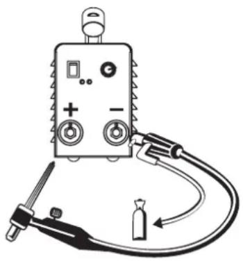
Illustration of a medical or industrial device with labeled ports and tubing (no text or symbols)To do TIG welding, follow these steps :
- Connect the earth clamp to the positive connector (+).
- Connect a valve torch to the negative connector (−) (option, ref. 044425)
- Connect the torch gas hose to the gas bottle regulator.
It may be necessary to cut it before the nut if it is not suitable for the regulator. - Activating the TIG mode with the switch on the front panel and adjust the intensity.
- Set the gas flow on the gas bottle regulator, then open the torch valve.
- To start the arc : make contact between the electrode and the workpiece.
- At the end of the weld: lift the torch quickly (up-down) to activate the automated downslope. This movement must be done at a height between 5 and 10 mm. Then close the torch valve to stop the gas after the electrode has cooled down.
Recommended combinations / electrode grinding
| Current (A) ∅ Electrode (mm) ∅ Nozzle (mm) | Flow rate(Argon L/mn) | ||
| 0.3 - 3 mm 5 - 75 | 1 6.5 6 - 7 | ||
| 2.4 - 6 mm 60 - 150 | 1.6 8 6 - 7 | ||
| 4 - 8 mm 100 - 200 | 2 9.5 7 - 8 | ||
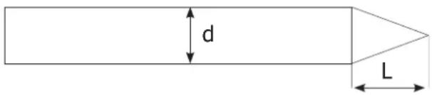
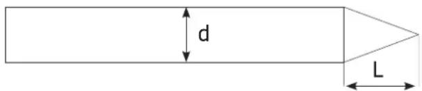
To optimise the welding process, it is recommended to grind the electrode prior to the welding, as described below:
$$ L = 3 \times d. $$
text_image
d LTROUBLESHOOTING
| Troubleshooting | Causes | Solutions | |
| MMA-TIG | The 2 indicators are on, but the machine does not deliver any current. | The thermal protection has switched on. | Wait for the end of the cooling cycle. |
| Current too high on the primary circuit. | Switch off the unit (with the on/off switch), then turn it on. | ||
| The green indicator is on, but the machine does not weld. | Fault with earth clamp/cable connection. | Check the connections | |
| The product is under voltage, you are feeling tingling when touching the machine's body. | The earth contact is faulty. | Check the plug and the earth of your installation. | |
| The machine welds poorly. | Polarity error (+/-). | Check the polarity (+/-) recommended on the electrode box. | |
| TIG | Instable arc | Default coming from the tungsten electrode | Use a tungsten electrode with the adequate size |
| Use a well prepared tungsten electrode | |||
| Too important gas flow rate Reduce gas flow rate | |||
| The tungsten electrode gets oxidised and tern at the end of welding. | Welding zone | Protect welding zone against air flows | |
| Default coming from post-gas or the gas has been stopped prematurely. | Check and tighten all gas connections. Wait until the electrode cools down before stopping the gas. | ||
| The electrode melts Polarity error | Check that the earth clamp is really connected to + | ||
WARRANTY
The warranty covers faulty workmanship for 2 years from the date of purchase (parts and labour).
The warranty does not cover:
- Transit damage.
- Normal wear of parts (eg. : cables, clamps, etc..).
- Damages due to misuse (power supply error, dropping of equipment, disassembling).
- Environment related failures (pollution, rust, dust).
In case of failure, return the unit to your distributor together with:
- The proof of purchase (receipt etc ...)
- A description of the fault reported

natural_image
Diagram of a medical or laboratory device with labeled ports and tubing (no text or symbols present)natural_image
Diagram of a medical or laboratory device with labeled ports and tubing (no readable text or symbols)natural_image
Diagram of a medical or industrial device with labeled ports and tubing (no readable text or symbols)WAARSCHUWINGEN - VEILIGHEIDSINSTRUCTIES
ALGEMENE INSTRUCTIES

natural_image
Illustration of a medical or industrial device with labeled ports and tubing (no text or symbols)natural_image
Illustration of a medical or laboratory device with labeled ports and tubing (no text or symbols)natural_image
Diagram of a medical or laboratory device with labeled ports and tubing (no text or symbols present)$$ L = 3 \times d $$
text_image
d LBŁĘDY, PRZYCZYNY, ROZWIĄZANIA
natural_image
Diagram of a medical or electrical device with labeled ports and tubing (no text or symbols present)text_image
Technical diagram of an electronic device with numbered components and labeled parts in Chinese| 1 | Bouton de potentiometre / Potentiometer button / Drehreglerknopf / Botón de potenciómetro / Кнопка потенциометра / Draaiknop / Pulsante del Potenziometro / Przycisk potencjometru / Knoflík potenciometru | 73099 |
| 2 | Indicateur / Warning Indicator / Warnungsindikator / Indicador de advertencia / Индикатор предупреждения / Waarschuwingsindicator / Indicatore di avvertimento / Wskaźnik / Indikátor | C13203 |
| 3 | Indicateur d'alimentation / Power Indicator / Leistungsanzeige / Indicador de potencia / Индикатор мощности / Vermogensindicator / Indicatore di potenza / Wskaźnik zasilania / Indikátor napájení | C13201 |
| 4 | Douilles / Texas Connector / Hülsen / Conectores / Гнезда / Fitting / Boccole / Gniazda / Zásuvky | C31312 |
| 5 | Carte électronique / Electonic board / Stuerplatine / Tarjeta electrónica / Электронная плата / Print plaat / Scheda elettrica / Karta elektroniczna / Hlavní deska | B4150 |
| 6 | Bouton marche/arrêt / On/off switch / Schalter Start/Stop / Botón Encendido/Apagado / Кнопка ВКЛ/ ВЫКЛ / Knop aan/uit / Pulsante avvio/stop / Przycisk włącznik/wyłącznik / Vypínač | C51529 |
| 7 | Cordon secteur / Power supply cable / Netzleitung / Cable de conexión eléctrica / Сетевой шнур / Elektrische netsnoer / Cavo corrente / Główny kabel / Napájecí kabel | 2.2 m 21468 |
| 8 | Ventillateur / Fan / Lüfter / Ventilador / Вентилятор / Ventilator / Ventilatore / Wentylator / Ventilátor | C16545 |
| 9 | Interrupteur / Switch / Schalter / Interruptor / Переключатель / Schakel / Interruttore / Przełącznik / Přepínač | C51559 |
| - | Porte électrodes / Electrode holder 1.6 m - 16 mm ^2 B331771 | |
| - | Pince de masse / Earth Cable 1.6 m - 16 mm ^2 B331770 |
INTERFACE / INTERFACE / BEDIENFELD / INTERFAZ / ИНТЕРФЕЙС / INTERFACE / INTERFACCIA / INTERFEJS / OVLÁDACÍ PANEL
natural_image
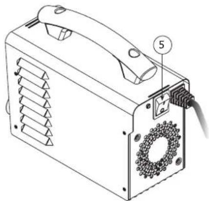
Technical line drawing of a portable electronic device with labeled ports (no text or symbols beyond numbered annotations)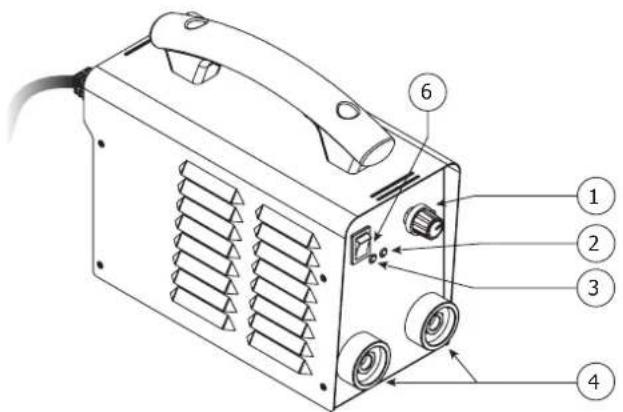
text_image
Technical diagram of a portable electronic device with numbered parts labeled 1 to 6| 1 | Potentiomètre de réglage courant / Current setting potentiometer / Drehregler / Potenciómetro de ajuste de corriente / Потенциометр настройки тока / Stroom instelling draaiknop / Potenziometro di regolazione di corrente / Potencjometr regulacji prądu. / Potenciometr nastavení proudu |
| 2 | Voyant jaune de protection thermique et surintensité / Yellow indicator for thermal protection and overcurrent / Gelbe Thermoschutzanzeige / Indicador amarillo de protección térmica y sobreintensidad. / Желтый светодиод-индикатор термозащиты и сверхтока / Gele lampje voor thermische beveiliging en overbelasting / Spia gialla di protezione termica e sovraintensità / Žółta kontrolka zabezpieczenia termicznego i przetężenia / Žlutá kontrolka tepelné a nadproudové ochrany |
| 3 | Voyant vert de fonctionnement / Green indicator (operation) / Grüne Betriebsanzeige / Indicador verde de funcionamiento / Зеленый светодиод-индикатор работы / Groene «aan» lampje / Spia verde di funzionamento / Zielona kontrolka działania / Zelená kontrolka provozu |
| 4 | Connecteur de raccordement pour porte-électrode et pince de masse / Earth clamp and electrode holder connectors / Steckverbindung für Elektrodenhalter und Masseklemme / Conector para conexión de portaelectrodos y pinza de masa / Коннектор подключения для электрододержателя и зажима массы / Aansluiting voor de elektrodehouder en de aardingsklem / Connettore di collegameto per porta elettrodo e morsetto di terra / Złącze przedłużenia uchwytu elektrody i zacisku uziemienia / Připoj držáku elektrody a zemnícího kabelu |
| 5 | Interrupteur Marche-Arrêt / ON-OFF switch / ON-OFF-Schalter / Interruptor ON-OFF / Переключатель ВКЛ-ВЫКЛ / AAN-UIT-schakelaar / Interruttore ON-OFF / Przełącznik ON-OFF / Vypínač ON-OFF |
| 6 | Interrupteur MMA-TIG Lift / MMA-TIG Lift switch / MMA-TIG Lift-Schalter / Interruptor MMA-TIG Lift / Переключатель MMA-TIG Lift / MMA-TIG Lift-schakelaar / Interruttore MMA-TIG Lift / Przełącznik MMA-TIG Lift / Vypínač MMA-TIG Lift |
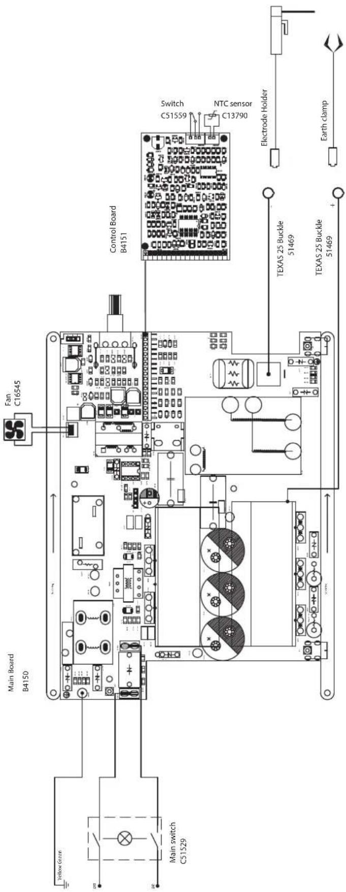
SCHÉMA ÉLECTRIQUE / CIRCUIT DIAGRAM / STROMLAUFPLAN / ESQUEMA ELÉCTRICO / ЭЛЕКТРИЧЕСКАЯ СХЕМА / ELEKTRISCH SCHEMA / SCHEMA ELETTRICO / SCHEMAT ELEKTRYCZNY / ELEKTRICKÁ SCHÉMA
text_image
Main Board B4150 Fan C16545 Yellow Green Main switch CS1529 Control Board B4151 Switch C1559 NTC sensor C13790 Electrode Holder TEXAS 25 Buckle 51469 TEXAS 25 Buckle 51469 + Earth clampSPÉCIFICATIONS TECHNIQUES / TECHNICAL SPECIFICATIONS / TECHNISCHE DATEN / ESPECIFICACIONES TÉCNICAS / ТЕХНИЧЕСКИЕ СПЕЦИФИКАЦИИ / TECHNISCHE GEGEVENS / SPECIFICHE TECNICHE / DANE TECHNICZNE / TECHNICKÉ VLASTNOSTI
| Primaire / Primary / Primär / Primario / Первичka / Primaire / Primario / Podstawowy | ||
| Tension d'alimentation / Power supply voltage / Stromversorgung / Tensión de red eléctrica / Напряжение питания / Voedingsspanning / Tensione di alimentazione / Napięcie zasilania | 230 V +/- 15% | |
| Fréquence secteur / Mains frequency / Netzfrequenz / Frecuencia / Частота сети / Frequentie sector / Frequenza settore / Częstotliwość sieci zasilania | 50 / 60 Hz | |
| Nombre de phases / Number of phases / Anzahl der Phasen / Número de fases / Количество фаз / Aantal fasen / Numero di fase / Liczba faz | 1 | |
| Fusible disjoncteur / Fuse / Sicherung / Fusible disyuntor / Fusible disyuntor / Плавкий предохранитель прерывателя / Zekering hoofdschakelaar / Fusibile disgiuntore / Wyrącznik bezpieczników | 16 A | |
| Courant d'alimentation effectif maximal I1eff / Maximum effective supply current I1eff / Corriente de alimentación efectiva máxima I1eff / Maximale effectieve voedingsstroom I1eff / Corrente di alimentazione effettiva massima I1eff / Maksymalny efektywny prąd zasilania I1eff | 14.5 A | |
| Courant d'alimentation maximal I1max / Maximum supply current I1max / Corriente de alimentación máxima I1max / Maximale voedingsstroom I1max / Corrente di alimentazione massima I1max / Maksymalny prąd zasilania I1max | 34 A | |
| Section du cordon secteur / Mains cable section / Sectie netsnoer / Sección del cable de alimentación / Sezione del cavo di alimentazione / Odcinek przewodu zasilającego | 3 × 1.5 mm^2 | |
| Puissance active maximale consommée / Maximum active power consumed / Consumo máximo de energía activa / Maximale actieve verbruikte vermogen / Potenza attiva massima consumata / Maksymalny pobór mocy czynnej | 4931 W | |
| Consommation au ralenti / Idle consumption / Consumo en ralentizado / Stationair verbruik / Consumo al mínimo / Zużycie na biegu jałowym | 41.4 W | |
| Rendement à I2max / Efficiency at I2max / Eficiencia a I2máx / Rendement bij I2max / Efficienza a I2max / Sprawność przy I2max | 85.7 % | |
| Facteur de puissance à I2max (λ) / Power factor at I2max (λ) / Factor de potencia a I2max (λ) / Inschakelduur bij I2max (λ) / Ciclo di potenza a I2max (λ) / Współczynnik mocy przy I2max (λ) | 0.64 | |
| Classe CEM / EMC class / Classe CEM / Klasse CEM / Classe CEM / Klasa EMC A | ||
| Secondaire / Secondary / Sekundar / Secundario / Вторичка / Secondair / Secondario / Zapasowy | MMA | TIG |
| Tension à vide / No load voltage / Leerlaufspannung / Tensión al vacío / Напряжение холостого хода / Nullastspanning / Tensione a vuoto / Napięcie próżniowe | 65 V | |
| Nature du courant de soudage / Type of welding current / Tipo de corriente de soldadura / Type lasstroom / Tipo di corrente di saldatura / Rodzaj prądu spawania | DC | |
| Modes de soudage / Welding modes / Modos de soldadura / Lasmodules / Modalità di saldatura / Tryby spawania | MMA, TIG Lift | |
| Courant de soudage minimal / Minimum welding current / Corriente mínima de soldadura / Minimale lasstroom / Corrente minima di saldatura / Minimalny prąd spawania | 10 A | |
| Courant de sortie nominal (I2) / Normal current output (I2) / nominaler Ausgangsstrom (I2) / Corriente de salida nominal (I2) / Номинальный выходной ток (I2) / Nominale uitgangsstroom (I2) / Corrente di uscita nominale (I2) / Nominalny prąd wyjściowy (I2) | 10 -160 A | |
| Tension de sortie conventionnelle (U2) / Conventional voltage output (U2) / entsprechende Arbeitsspannung (U2) / Tensión de salida convencional (U2) / Условное выходные напряжения (U2) / Conventionele uitgangsspanning (U2) / Tensione di uscita convenzionale (U2) / Konwencjonalne napięcie wyjściowe (U2) | 20.4 V - 26.4 V | 10.4 V - 16.4 V |
| Facteur de marche à 40°C (10 min)*Norme EN60974-1.Duty cycle at 40°C (10 min)*Standard EN60974-1.Einschaltdauer @ 40°C (10 min)*EN60974-1 -Norm.Ciclo de trabajo a 40°C (10 min)*Norma EN60974-1 | ПВ% при 40°C (10 мин)*Норма EN60974-1.Inschakelduur bij 40°C (10 min)*Norm EN60974-1.Ciclo di lavoro a 40°C (10 min)*Norma EN60974-1.Cykl pracy w 40°C (10 min)*Norma EN60974-1. | Imax 10 % 13 %60% 75 A 85 A100% 65 A 75 A |
| Température de fonctionnement / Functionning temperature / Betriebstemperatur / Temperatura de funcionamiento / Рабочая температура / Gebruikstemperatuur / Temperatura di funzionamento / Temperatura urządzenia podczas pracy | -10°C → +40°C | |
| Température de stockage / Storage temperature / Lagerungstemperatur / Temperatura de almacenaje / Температура хранения / Bewaartemperatuur / Temperatura di stoccaggio / Temperatura przechowywania | -20°C → +55°C | |
| Degré de protection / Protection level / Schutzgrad / Grado de protección / Степень защиты / Beschermingsklasse / Grado di protezione / Stopień ochrony | IP21 | |
| Classe d'isolation minimale des enroulements / Minimum coil insulation class / Clase mínima de aislamiento del bobinado / Minimale isolatieklasse omwikkelingen / Classe minima di isolamento degli avvolgimenti / Minimalna klasa izolacji okablowania | F | |
| Dimensions (Lxbxh) / Dimensions (Lxlxh) / Abmessung (LxBxH) / Dimensiones (Lxlxh) / Размеры (ДхШхВ) / Afmetingen (Lxlxh) / Dimensioni (Lxlxh) / Wymiary (DxSxW) | 23 × 19.5 × 10 cm | |
| Poids / Weight / Gewicht / Peso / Bec / Gewicht / Peso / Waga | 3.0 kg | |
| Poids avec accessoires / Weight with accessories / Gewicht mit Zubehör / Peso con accesorios / Bec с аксессуарами / Gewicht met accessoires / Peso con accessori / Waga z akcesoriami / Hmotnost s příslušenstvím | 4.6 kg | |
*The duty cycles are measured according to standard EN60974-1 à 40°C and on a 10 min cycle. While under intensive use (> to duty cycle) the thermal protection can turn on, in that case, the arc swictes off and the indicator switches on. Keep the machine's power supply on to enable cooling until thermal protection cancellation. The welding power source describes an external drooping characteristic.