SI 130TUR+ - Heat pump DIMPLEX - Free user manual and instructions
Find the device manual for free SI 130TUR+ DIMPLEX in PDF.


| Product type | Reversible brine-to-water heat pump for indoor installation |
| Brand | Dimplex |
| Model | SI 130TUR+ |
| Dimensions (H x W x D) | 1890 x 1350 x 775 mm |
| Weight | 830 kg |
| Power supply (power) | 3~/PE 400 V, 50 Hz, fuse C80A |
| Power supply (control) | 1~/N/PE 230 V, 50 Hz, fuse C13A |
| Refrigerant | R410A, 16.9 kg, GWP 2088 |
| Lubricant | Polyolester (POE), 10.0 liters |
| Heating capacity (B0/W35) | 108.5 kW (2 compressors) |
| COP (B0/W35) | 4.2 (2 compressors) |
| Cooling capacity (B20/W7) | 129.0 kW (2 compressors) |
| Sound power level | 76 dB(A) |
| Sound pressure level at 1 m | 60 dB(A) |
| Minimum heating water flow rate | 19.0 m³/h |
| Brine flow rate | 24.5 m³/h |
| Heating water temperature range | 20 °C to 58 °C |
| Brine temperature range (heating) | -5 °C to +25 °C |
| Protection | IP21 |
| Heating connections | External threaded connection 3 inches |
| Heat source connections | External threaded connection 3 inches |
| Domestic hot water connections | Internal/external threaded connection 1 1/2 inches |
| Maintenance | Filter cleaning after commissioning, annual leak test of refrigerant circuit (if >6 kg) |
| Safety | Mandatory flow switch, integrated frost protection, emergency stop |
| Included accessories | Outdoor sensor, filter, flow switch |
Frequently Asked Questions - SI 130TUR+ DIMPLEX
User questions about SI 130TUR+ DIMPLEX
0 question about this device. Answer the ones you know or ask your own.
Ask a new question about this device
Download the instructions for your Heat pump in PDF format for free! Find your manual SI 130TUR+ - DIMPLEX and take your electronic device back in hand. On this page are published all the documents necessary for the use of your device. SI 130TUR+ by DIMPLEX.
USER MANUAL SI 130TUR+ DIMPLEX
natural_image
Technical line drawing of a rectangular industrial machine with a vertical slatted section and a curved top component (no text or symbols)Installation and Operating Instructions
Reversible Brine-to-Water Heat Pump for Indoor Installation
natural_image
White electronic device with ventilation slots and a circular vent (no text or symbols visible)natural_image
Technical line drawing of a mechanical assembly or mounting bracket with no visible text or symbols1 Please Read Immediately....EN-2
1.1 Important Information...... EN-2
1.2 Intended Use ...... EN-2
1.3 Legal regulations and directives ...... EN-2
1.4 Energy-Efficient Use of the Heat Pump ...... EN-3
2 Purpose of the Heat Pump ...... EN-3
2.1 Application ...... EN-3
2.2 Operation principle...... EN-3
2.3 Functional description for integrated thermal energy metering...... EN-3
3 Basic device......EN-4
4 Accessories....EN-4
4.1 Connecting Flanges...... EN-4
4.2 External four-way reversing valve, Water circuit side ...... EN-4
4.3 Remote control ...... EN-4
4.4 Building management technology....EN-5
4.5 Room climate control station EN-5
4.6 Thermal energy meter WMZ...... EN-5
5 Transport......EN-6
6 Installation ...... EN-6
6.1 General......EN-6
6.2 Sound Emissions ...... EN-6
7 Assembly ...... EN-6
7.1 General......EN-6
7.2 Connection on heating and hot water side ...... EN-7
7.3 Connection on heat source side ...... EN-7
7.4 Temperature sensor ...... EN-8
7.5 Electrical connection....EN-9
8 Start-Up......EN-10
8.1 General......EN-10
8.2 Preparation ...... EN-10
8.3 Procedure ...... EN-10
9 Cleaning / Maintenance ...... EN-11
9.1 Maintenance ...... EN-11
9.2 Cleaning the Heating System...... EN-11
9.3 Cleaning the Heat Source System...... EN-11
9.4 Maintenance ...... EN-11
10 Faults / Troubleshooting ...... EN-11
11 Decommissioning / Disposal ...... EN-11
12 Device Information......EN-12
Anhang / Appendix / Annexes ...... A-I
Maßbild / Dimension drawing / Schéma coté....A-II
Diagramme / Characteristic Curves / Diagrammes....A-III
1 Please Read Immediately
1.1 Important Information
ATTENTION!
Any work on the heat pump may only be performed by an authorised and qualified customer service.
ATTENTION!
When operating or maintaining a heat pump, the legal requirements of the country where the heat pump is operated apply. Depending on the refrigerant quantity, the heat pump must be inspected for leaks at regular intervals by a certified technician, and these inspections must be recorded.
ATTENTION!
If the heat pump or circulating pump is controlled externally, an flow rate switch is required to prevent the compressor from being switched on when there is no volume flow.
ATTENTION!
The heat pump must not be tilted more than max. 45^ (in either direction).
ATTENTION!
The transport securing device is to be removed prior to commissioning.
ATTENTION!
The heating system must be flushed prior to connecting the heat pump.
ATTENTION!
It is recommend that the water circuit side be equipped with the flow rate switch available as an option.
ATTENTION!
The supplied strainer must be fitted in the heat source inlet of the heat pump in order to protect the evaporator against the ingress of impurities.
ATTENTION!
The brine solution must contain at least 25% of an antifreeze agent on a mono-ethylene glycol or propylene glycol basis and must be mixed prior to filling.
ATTENTION!
Ensure the rotary field is clockwise when connecting the mains cables (if the rotary field is not clockwise, the heat pump will not work properly, is very loud and may cause damage to the compressor).
ATTENTION!
It is not permitted to connect more than one electronically regulated circulating pump via a relay output.
ATTENTION!
Commissioning is to be effected in accordance with the installation and operating manual of the heat pump manager.
ATTENTION!
The supplied strainer must be fitted in the heat source inlet of the heat pump in order to protect the evaporator against the ingress of impurities.
ATTENTION!
Disconnect all electrical circuits from the power supply before opening the enclosure.
1.2 Intended Use
This device is only intended for use as specified by the manufacturer. Any other use beyond that intended by the manufacturer is prohibited. This requires the user to abide by the relevant project planning documents. Please refrain from tampering with or altering the device.
1.3 Legal regulations and directives
This heat pump is designed for use in a domestic environment according to Article 1, Paragraph 2 k) of EC directive 2006/42/EC (machinery directive) and is thus subject to the requirements of EC directive 2006/95/EC (low-voltage directive). It is thus also intended for use by non-professionals for heating shops, offices and other similar working environments, in agricultural establishments and in hotels, guest houses and similar / other residential buildings.
This heat pump conforms to all relevant DIN/VDE regulations and EU directives. For details refer to the EC Declaration of Conformity in the appendix.
The electrical connection of the heat pump must be performed according to and conforming with all relevant VDE, EN and IEC standards. Beyond that, the connection requirements of the local utility companies have to be observed.
The heat pump is to be connected to the heat source system and the heating or cooling system in accordance with all applicable regulations.
Persons, especially children, who are not capable of operating the device safely due to their physical, sensory or mental abilities or their inexperience or lack of knowledge, must not operate this device without supervision or instruction by the person in charge.
Children must be supervised to ensure that they do not play with the device.
ATTENTION!
Any work on the heat pump may only be performed by an authorised and qualified customer service.
ATTENTION!
When operating or maintaining a heat pump, the legal requirements of the country where the heat pump is operated apply. Depending on the refrigerant quantity, the heat pump must be inspected for leaks at regular intervals by a certified technician, and these inspections must be recorded.
More information is available in the chapter Care / Cleaning.
1.4 Energy-Efficient Use of the Heat Pump
By operating this heat pump you contribute to the protection of our environment. The heating or cooling system and the heat source must be properly designed and dimensioned to ensure efficient operation. In particular, it is important to keep water flow temperatures as low as possible. All energy consumers connected should therefore be suitable for low flow temperatures. A 1 K higher heating water temperature corresponds to an increase in power consumption of approx. 2.5 %. Low-temperature heating systems with flow temperatures between 30 °C and 50 °C are optimally suited for energy-efficient operation.
2 Purpose of the Heat Pump
2.1 Application
The brine-to-water heat pump is to be used exclusively for the heating and cooling of heating water. It can be used in new or previously existing heating systems. The mixture of water and frost protection (brine) acts as a heat transfer medium in the heat source system. Ground probes, ground heat collectors or similar systems can be used as heat source systems.
2.2 Operation principle
Heating
The heat generated by the sun, wind and rain is stored in the ground. This heat stored in the ground is collected at low temperature by the brine circulating in the ground collector, ground coil or similar device.
A circulating pump then conveys the warmed brine to the evaporator of the heat pump. There, the heat is given off to the refrigerant in the refrigeration cycle. When so doing, the brine cools so that it can again take up heat energy in the brine circuit.
The refrigerant is drawn in by the electrically driven compressor, is compressed and "pumped" to a higher temperature level. The electrical power needed to run the compressor is not lost in this process, but most of the generated heat is transferred to the refrigerant.
Subsequently, the refrigerant is passed through the condenser where it transfers its heat energy to the heating water. Based on the thermostat setting, the heating water is thus heated to up to 58 °C.
Cooling
The functions of the evaporator and the liquifier are reversed in the "Cooling" operating mode.
The heating water gives up its heat to the refrigerant via the liquifier which is now functioning as an evaporator. The refrigerant is pumped to a higher temperature level using the compressor. Heat passes into the brine via the liquifier (evaporator in heating operation) and consequently into the ground.
2.3 Functional description for integrated thermal energy metering
The compressor manufacturer's performance specifications for different pressure levels are stored in the heat pump software. Two additional pressure sensors for determining the current pressure level are installed in the refrigerating circuit, one before and after the compressor. The current heat output can be calculated from the compressor data stored in the software and the current pressure level. The integral for the heat output over the runtime gives the quantity of thermal energy supplied by the heat pump, which is displayed separately for heating, domestic hot water preparation and swimming pool water preparation on the manager's display.
3 Basic device
The basic device consists of a ready-to-use heat pump for indoor installation, complete with sheet metal casing, control panel and integrated heat pump manager. The refrigerant circuit is hermetically sealed. It contains the Kyoto protocol approved refrigerant R410A with a GWP value of 2088. It is CFC-free, does not deplete ozone and is non-flammable.
All components required for the operation of the heat pump are located in the control box. An external temperature sensor including fixing accessories, a dirt trap and a flow rate switch, is supplied with the heat pump. The supply for the load current and the control voltage must be installed by the customer.
The control wire of the brine pump (to be provided by the customer) is to be connected to the control box. When so doing, a motor protecting device is to be installed, if required.
The customer must provide both the heat source system and the brine circuit manifold.
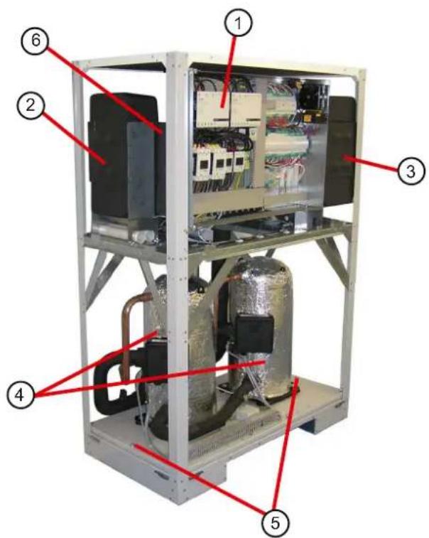
1) Control
2) Evaporator
3) Liquefier
4) Compressor
5) Transport securing devices
6) Hot water liquefier
4 Accessories
4.1 Connecting Flanges
The use of flat-sealing connecting flanges allows the unit, as an option, to be connected by means of flanges.
4.2 External four-way reversing valve, Water circuit side
The external four-way reversing valve (Y12) enables optimised heating and cooling operation of the reversible brine-to-water heat pump. The reversal of the flow direction ensures an optimum flow through the heat exchanger on the water circuit side both in heating operation and in cooling operation in the opposite direction. The electrical actuator required for the automatic switching is controlled by the heat pump manager. (Max. permissible switching current 2A).
If the external four-way reversing valve is not used, the heat outputs and the COPs are reduced as specified in the device information. With heating-only operation without an external four-way valve, the hydraulic connection should be carried out such that the heat exchanger is loaded in the opposite direction (observe note in section 7.2 „Connection on heating and hot water side“).
The external four-way reversing valve with a set time of max. 60 seconds, which is available as special accessory, ensures switching of the water flow over the complete range of operating temperatures without any mixing losses.
The hydraulic and electrical circuit diagrams in the appendix show the basic design. Detailed installation instructions are provided with the four-way reversing valve.
4.3 Remote control
A remote control adds convenience and is available as a special accessory. Operation and menu navigation are identical to those of the heat pump manager. Connection takes place via an interface (special accessories) with RJ 12 Western plug.
NOTE
In the case of heating controllers with a removable operating element, this can also be used directly as a remote control.
4.4 Building management technology
The heat pump manager can be connected to a building management system network via supplementation of the relevant interface plug-in card. The supplementary installation instructions of the interface card must be consulted regarding the exact connection and parameterisation of the interface.
The following network connections can be made on the heat pump manager:
Modbus
EIB, KNX
Ethernet
ATTENTION!
If the heat pump or circulating pump is controlled externally, an flow rate switch is required to prevent the compressor from being switched on when there is no volume flow.
4.5 Room climate control station
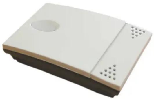
With cooling using panel heating/cooling systems, regulation is carried out according to the room temperature and humidity measured by the room climate control station.
This is done by setting the desired room temperature on the heat pump manager. The minimum possible cooling water temperature is calculated from the room temperature and humidity measured in the reference room. The control response of the cooling system is influenced by the currently measured room temperature and the set room set temperature.
natural_image
White electronic device with ventilation slots and a circular vent (no text or symbols visible)Fig. 4.1: Room climate control station
4.6 Thermal energy meter WMZ
4.6.1 General description
The thermal energy meter (WMZ 25/32) is used for measuring the quantity of thermal energy supplied. It is available as an accessory. Due to the additional heat exchanger, two thermal energy meters are required for measuring the quantity of thermal energy.
Sensors in the flow and return of the heat exchanger pipes and an electronics module acquire the measured values and transmit a signal to the heat pump manager, which, depending on the current operating mode of the heat pump (heating/DHW/swimming pool), totals the thermal energy in kWh and displays them in the operating data and history menu.
i NOTE
The thermal energy meter complies with the quality requirements of the German market incentive programme subsidising efficient heat pumps. The thermal energy meter is not subject to obligatory calibration, and can thus not be used for the heating cost billing procedure!
4.6.2 Hydraulic and electrical integration of the thermal energy meter
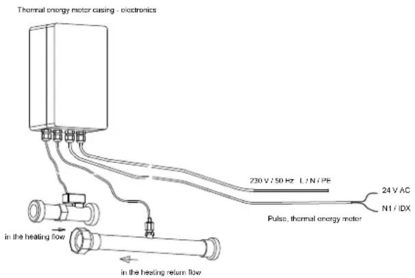
The thermal energy meter requires two measuring devices for data acquisition.
A measuring tube for the flow measurement
This must be installed in the heat pump flow (observe flow direction).
A temperature sensor (copper pipe with immersion sleeve)
This must be installed in the heat pump return.
The installation locations for both measuring tubes should be as close to the heat pump as possible in the generator circuit.
The distance from pumps, valves and other installations must be taken into account, as eddying effects could lead to incorrect thermal energy metering (a calming section of 50 cm is recommended).
5 Transport
For the transport by means of a hand truck or boiler trolley, position the latter under the front end of the unit below the transport security device.
For transport on a level surface, the unit can be lifted from the rear or from the front by means of a lift truck or forklift. In this case, the transport securing device is not imperative.
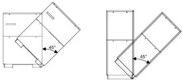
ATTENTION!
The heat pump must not be tilted more than max. 45° (in either direction).
natural_image
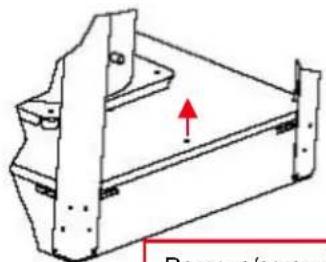
Technical line drawing of a mechanical bracket with mounting holes and a red arrow indicating direction (no text or symbols)Remove/screw in transport lock
After the transport, the transport securing device is to be removed on either side at the bottom of the unit.
ATTENTION!
The transport securing device is to be removed prior to commissioning.
To remove the panelling, open the individual covers by unscrewing the respective turn-lock fasteners and then gently tilting the covers away from the device. Then lift them up out of the mountings.
6 Installation
6.1 General
The brine-to-water heat pump must be installed in a frost-free, dry room on an even, smooth and horizontal surface. The entire frame should lie directly on the floor to ensure an adequate soundproof seal. Failing this, additional sound insulation measures may become necessary.
The heat pump should be installed to allow easy maintenance/service access. This is ensured if a clearance of approx. 1 m in front of the heat pump is maintained.
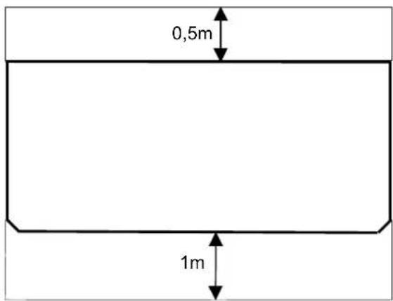
Neither frost nor temperatures higher than 25 °C must occur in the installation location at any time of the year.
6.2 Sound Emissions
The heat pump offers silent operation due to efficient sound insulation. Any vibration transmission to the foundation or the heating system can be largely prevented by internal sound decoupling measures.
7 Assembly
7.1 General
The following connections need to be established on the heat pump:
■ supply/return flow of the brine system
■ Flow / return of additional heat exchanger
■ supply/return flow of the heating system
Voltage supply
■ temperature sensor
7.2 Connection on heating and hot water side
ATTENTION!
The heating system must be flushed prior to connecting the heat pump.
Before completing the heat pump connections on the heating water side, the heating installation must be flushed in order to remove any impurities that may be present, as well as residues of sealing material, and the like. Any accumulation of deposits in the condenser may result in a total failure of the heat pump.
ATTENTION!
It is recommend that the water circuit side be equipped with the flow rate switch available as an option.
Once the installation on the heating side has been completed, the heating system must be filled, de-aerated and pressure-tested.
Consideration must be given to the following when filling the system:
■ Untreated filling water and make-up water must be of drinking water quality
(colourless, clear, free from sediments)
- Filling water and make-up water must be pre-filtered (pore size max. 5 µm).
Scale formation in hot water heating systems cannot be completely avoided, but in systems with flow temperatures below 60 °C the problem can be disregarded.
With medium and high-temperature heating systems, temperatures above 60 °C can be reached.
The following standard values should therefore be adhered to concerning the filling water and make-up water (according to VDI 2035 Sheet 1):
| Total heat output in [kW] | Total alkaline earths in mol/m3 and/or mmol/l | Total hardness in °dH |
| up to 200 | ≤ 2.0 ≤ 11.2 | |
| 200 to 600 | ≤ 1.5 ≤ 8.4 | |
| >600 < 0.02 < 0.11 | ||
Use of the optionally available four-way reversing valve is recommended. A detailed installation description can be found in the instructions included with the valve.
Note:
For operation of the heat pump with the four-way reversing valve, it is essential to set up the hydraulic connections according to the instructions included in the scope of supply of the valve. The instructions give a description of the precise procedure for the correct assembly of hydraulics. Non-observance of this will lead to restrictions in the operation of the heat pump.
Important:
The notes/settings in the instructions of the heat pump manager must always be observed and carried out accordingly; not doing so will lead to malfunctions.
Heating water minimum flow rate
The minimum heating water flow rate through the heat pump must be assured in all operating states of the heating system. This can be accomplished, for example, by installing a dual differential pressureless manifold.
Provided the heat pump manager and heating circulating pumps are ready for operation, the frost protection feature of the heat pump manager is active. If the heat pump is taken out of service or in the event of a power failure, the system has to be drained. In heat pump installations where a power failure cannot be readily detected (holiday house), the heating circuit must contain a suitable antifreeze product.
7.3 Connection on heat source side
The following procedure must be observed when making the connection:
Connect the brine pipe to the heat source flow and return of the heat pump.
The hydraulic integration diagram must be adhered to.
ATTENTION!
The supplied strainer must be fitted in the heat source inlet of the heat pump in order to protect the evaporator against the ingress of impurities.
ATTENTION!
It is recommended that the brine circuit side be equipped with the flow rate switch available as an option.
The brine liquid must be produced prior to charging the system. The brine concentration must be at least 25 %. Freeze protection down to approx. -14 °C can thus be ensured.
Only antifreeze products on the basis of mono-ethylene glycol or propylene glycol may be used.
The heat source system must be vented (de-aerated) and checked for leaks.
ATTENTION!
The brine solution must contain at least 25 % of an antifreeze agent on a mono-ethylene glycol or propylene glycol basis and must be mixed prior to filling.
i NOTE
A suitable de-aerator (micro bubble air separator) must be installed in the heat source circuit by the customer.
7.4 Temperature sensor
The following temperature sensors are already installed or must be installed additionally:
■ External temperature sensor (R1) supplied (NTC-2)
■ Return temperature heating circuit (R2) installed (NTC-10)
■ Return temperature primary circuit (R24) installed (NTC-10)
■ Flow temperature heating circuit (R9) installed (NTC-10)
■ Flow temperature primary circuit (R6) installed (NTC-10)
7.4.1 Sensor characteristic curves
| Temperature in °C | -20 | -15 | -10 | -5 | 0 | 5 | 10 | ||
| NTC-2 in kΩ | 14.6 | 11.4 | 8.9 | 7.1 | 5.6 | 4.5 | 3.7 | ||
| NTC-10 in kΩ | 67.7 | 53.4 | 42.3 | 33.9 | 27.3 | 22.1 | 18.0 | ||
| 15 | 20 | 25 | 30 | 35 | 40 | 45 | 50 | 55 | 60 |
| 2.9 | 2.4 | 2.0 | 1.7 | 1.4 | 1.1 | 1.0 | 0.8 | 0.7 | 0.6 |
| 14.9 | 12.1 | 10.0 | 8.4 | 7.0 | 5.9 | 5.0 | 4.2 | 3.6 | 3.1 |
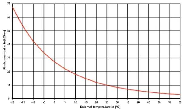
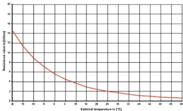
The temperature sensors to be connected to the heat pump manager must correspond to the sensor characteristic curve illustrated in Fig.7.1 on pag. 8. The only exception is the external temperature sensor included in the scope of supply of the heat pump (see Fig.7.2 on pag. 8)
line
| External temperature in [°C] | Resistance value in [kJ·h·m] | | ---------------------------- | ----------------------------- | | -20 | 70 | | -15 | 50 | | -10 | 40 | | -5 | 30 | | 0 | 25 | | 5 | 20 | | 10 | 15 | | 15 | 12 | | 20 | 10 | | 25 | 8 | | 30 | 7 | | 35 | 6 | | 40 | 5 | | 45 | 4 | | 50 | 3 | | 55 | 2 | | 60 | 1 |Fig. 7.1: Sensor characteristic curve NTC-10
line
| External temperature in [°C] | Resistance value in [kOhm] | |---|---| | -20 | 14.0 | | -15 | 11.5 | | -10 | 9.0 | | -5 | 6.5 | | 0 | 5.0 | | 5 | 4.0 | | 10 | 3.5 | | 15 | 3.0 | | 20 | 2.5 | | 25 | 2.0 | | 30 | 1.8 | | 35 | 1.5 | | 40 | 1.3 | | 45 | 1.1 | | 50 | 1.0 | | 55 | 0.8 | | 60 | 0.7 |Fig. 7.2: Sensor characteristic curve, NTC-2 according to DIN 44574 External temperature sensor
7.4.2 Mounting the external temperature sensor
The temperature sensor must be mounted in such a way that all weather conditions are taken into consideration and the measured value is not falsified.
■ Mount on the external wall on the north or north-west side where possible
- Do not install in a “sheltered position” (e.g. in a wall niche or under a balcony)
■ Not in the vicinity of windows, doors, exhaust air vents, external lighting or heat pumps
■ Not to be exposed to direct sunlight at any time of year
Sensor lead: Max. length 40 m; min. core cross-section 0.75 mm²; external diameter of the cable 4-8 mm.
7.4.3 Installing the strap-on sensor
It is only necessary to mount the strap-on sensors if they are included in the scope of supply of the heat pump but have not yet been installed.
The strap-on sensors can be fitted as pipe-mounted sensors or installed in the immersion sleeve of the compact manifold.
Mounting as a pipe-mounted sensor
■ Remove paint, rust and scale from heating pipe.
- Coat the cleaned surface with heat transfer compound (apply sparingly).
- Attach the sensor with a hose clip (tighten firmly, as loose sensors can cause malfunctions) and thermally insulate.

7.4.4 Hydraulic distribution system
The compact manifold and the dual differential pressureless manifold function as an interface between the heat pump, the heating distribution system, the buffer tank and, in some cases, even the hot water cylinder. A compact system is used to simplify the installation process, so that a lot of different components do not have to be installed individually. Further information can be found in the relevant installation instructions.
Compact manifold
The return sensor can remain in the heat pump, or should be installed in the immersion sleeve. The remaining empty space between the sensor and the immersion sleeve must be filled completely with heat transfer compound.
Dual differential pressureless manifold
In order for the heating circuit pumps of the generator and consumer circuits to supply the flow to the return sensor, this must be installed in the immersion sleeve of the dual differential pressureless manifold.
7.5 Electrical connection
7.5.1 General
All electrical connection work must be carried out by a trained electrician or a specialist for the specified tasks in accordance with the
■ installation and operating instructions,
■ country-specific installation regulations (e.g. VDE 0100),
■ technical connection conditions of the energy suppliers and supply grid operators (e.g. TAB) and
■ local conditions.
To ensure that the frost protection function of the heat pump works properly, the heat pump manager must remain connected to the power supply and the flow must be maintained through the heat pump at all times.
The switching contacts of the output relay are interference-suppressed. Therefore, depending on the internal resistance of the measuring instrument, a voltage can also be measured when the contacts are open. However, this will be much lower than the line voltage.
Extra-low voltage is connected to controller terminals N1-J1 to N1-J11; N1-J19; N1-J20; N1-J23 to N1-J26; N17-J1 to N17-J4; N17-J9; N17-J10 and terminal strips X3 and X5.1. If, due to a wiring error, the line voltage is mistakenly connected to these terminals, the heat pump manager will be destroyed
7.5.2 Electrical installation
1) The electric supply cable for the output section of the heat pump (up to 4-core) is fed from the electricity meter of the heat pump via the utility blocking contactor (if required) into the heat pump Connection of the mains cable to the control panel of the heat pump via terminal X1: L1/L2/L3/PE.
An all-pole disconnecting device with a contact gap of at least 3 mm (e.g. utility blocking contactor or power contactor) and an all-pole circuit breaker with common tripping for all external conductors must be installed in the power supply for the heat pump (tripping current and characteristic in compliance with the device information).
ATTENTION!
Ensure the rotary field is clockwise when connecting the mains cables (if the rotary field is not clockwise, the heat pump will not work properly, is very loud and may cause damage to the compressor).
2) The three-core electric supply cable for the heat pump manager (heating controller N1) is fed into the heat pump.
Connection of the control line to the control panel of the heat pump via terminal X2: L/N/PE.
Details on the power consumption of the heat pump are listed on both the product information sheet and the type plate.
The (L/N/PE\~230 V, 50 Hz) supply cable for the heat pump manager must have a constant voltage. For this reason, it should be tapped upstream from the utility blocking contactor or be connected to the household current, as important protection functions could otherwise be lost during a utility block.
3) The utility blocking contactor (K22) with 3 main contacts (1/3/5 // 2/4/6) and an auxiliary contact (NO contact 13/14) should be dimensioned according to the heat pump output and must be supplied by the customer.
The NO contact of the utility blocking contactor (13/14) is looped from terminal strip X3/G to connector terminal X3/A1. CAUTION! Extra-low voltage!
4) The contactor (K20) for the immersion heater (E10) of mono energy systems (HG2) should be dimensioned according to the radiator output and must be supplied by the customer. It is controlled (230 V AC) by the heat pump manager via terminals X2/N and X2/K20.
5) The contactor (K21) for the flange heater (E9) in the hot water cylinder should be dimensioned according to the radiator output and must be supplied by the customer. It is controlled (230 V AC) by the heat pump manager via terminals X2/N and X2/K21.
6) The contactors mentioned above in points 3, 4 and 5 are installed in the electrical distribution system. Mains cables for the installed heaters must be laid and secured in accordance with the valid standards and regulations.
7) All installed electric cables must have permanent wiring.
8) The heat circulating pump (M13) is activated via the contact N1-J13/NO5. The connection points for the pump are X2/M13 and X2/N. When using pumps where the switching capacity exceeds the output, a coupling relay must be interposed.
9) The auxiliary circulating pump (M16) is activated via the contact N1-J16/NO9. The connection points for the pump are X2/M16 and X2/N. When using pumps where the switching capacity exceeds the output, a coupling relay must be interposed.
10) The domestic hot water circulating pump (M18) is activated via the contact N1-J13/NO6. The connection points for the pump are X2/M13 and X2/N. When using pumps where the switching capacity exceeds the output, a coupling relay must be interposed.
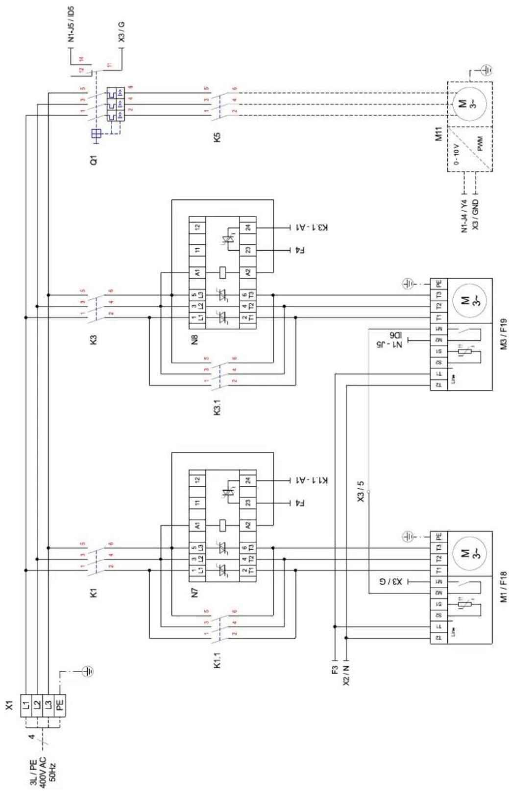
11) The brine or well pump (M11) is activated via the contact N1-J12/NO3. The connection point for the pump is on contactor K5:2/4/6. A coupling relay is already integrated in this output.. If an additional well pump is used, the protective motor switch at the site must be checked and replaced if necessary.
Connection of the well pump mains cable on the heat pump's control panel via terminal X1: L11/L21/L31/PE. Ensure that the supply voltage for these terminals cannot be switched off by the tariff contactor when connecting the mains cable for the well pump, in order to safeguard the switch-off delay of the well pump.
12) The return flow sensor is integrated into the heat pumps. The return flow sensor must be installed in the immersion sleeve in the manifold only when a dual differential pressureless manifold is used. The single-core wires are then connected to terminals X3/GND and X3/R2.1. Bridge A-R2 (situated between X3/U2 and X3/1 when delivered) must then be moved to terminals X3/1 and X3/2.
13) The external sensor (R1) is connected to terminals X3/GND and X3/R1.
14) The domestic hot water sensor (R3) is included with the domestic hot water cylinder and is connected to terminals X3/GND and X3/R3.
natural_image
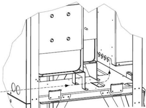
Technical line drawing of a mechanical assembly with no visible text or symbolsAll lines must be fed into the device from the back and secured at the switch box using cable connectors. They must additionally be secured with a strain relief.
7.5.3 Connecting an electronically regulated circulating pump
Electronically regulated circulating pumps have high starting currents, which may shorten the service life of the heat pump manager. For this reason, a coupling relay is installed or must be installed between the output of the heat pump manager and the electronically regulated circulating pump. This is not necessary if the permissible operating current of 2 A and a maximum starting current of 12 A are not exceeded in the electronically regulated circulating pump or if express approval has been issued by the pump manufacturer.
ATTENTION!
It is not permitted to connect more than one electronically regulated circulating pump via a relay output.
8 Start-Up
8.1 General
To ensure that start-up is performed correctly, it should only be carried out by an after-sales service technician authorised by the manufacturer. These measures can also include an additional warranty under certain conditions (see Warranty). Start-up should be carried out in heating operation.
8.2 Preparation
Prior to commissioning, the following items need to be checked:
All connections of the heat pump must have been made as described in Chapter 7.
The heat source system and the heating circuit must have been filled and checked.
■ The strainer must have been fitted in the sole inlet of the heat pump.
In the brine and heating circuits all valves that might impair the proper flow must be open.
The settings of the heat pump manager must be adapted to the heating installation in accordance with the instructions contained in the controller's operating manual.
8.3 Procedure
The start-up of the heat pump is effected via the heat pump manager.
ATTENTION!
Commissioning is to be effected in accordance with the installation and operating manual of the heat pump manager.
9 Cleaning / Maintenance
9.1 Maintenance
To prevent malfunctions due to sediments in the heat exchangers, care must be taken that no im-purities can enter the heat source system and the heating installation. In the event that operating malfunctions due to contamination occur nevertheless, the system should be cleaned as described below.
9.2 Cleaning the Heating System
The ingress of oxygen into the heating water circuit may result in the formation of oxidation products (rust), particularly if steel components are used. They enter the heating system via the valves, the circulating pumps and/or plastic pipes. It is therefore essential - in particular with respect to the entire pipework - that only diffusion-resistant materials are used.
i NOTE
We recommend the installation of a suitable corrosion protection system to prevent the formation of deposits (e.g. rust) in the condenser of the heat pump. We recommend equipping diffusion-open heating systems with an electrophysical anti-corrosion system (e.g. ELYSATOR system).
Residue from lubricants and sealants may also contaminate the heating water.
In the case of severe contamination leading to a reduction in the performance of the liquefier in the heat pump, the system must be cleaned by a heating technician.
Based on current information, we recommend using a 5 % phosphoric acid solution for cleaning purposes. However, if cleaning needs to be performed more frequently, a 5 % formic acid solution should be used.
In either case, the cleaning fluid should be at room temperature. We recommend flushing the heat exchanger in the direction opposite to the normal flow direction.
To prevent acidic cleaning agents from entering the heating system circuit, we recommend connecting the flushing device directly to the flow and return of the liquefier of the heat pump.
It is then important that the system be thoroughly flushed using appropriate neutralising agents to prevent any damage from being caused by cleaning agent residue remaining in the system.
Acids must be used with care and the regulations of the employers' liability insurance associations must be adhered to.
The manufacturer's instructions regarding cleaning agent must be complied with at all times.
9.3 Cleaning the Heat Source System
ATTENTION!
The supplied strainer must be fitted in the heat source inlet of the heat pump in order to protect the evaporator against the ingress of impurities.
The filter sieve of the dirt trap should be cleaned one day after start-up. Further checks must be set according to the level of dirt. If no more contamination can be noticed any more, the strainer filter can be removed in order to reduce pressure losses.
9.4 Maintenance
According to regulation (EC) No. 842/2006, all refrigerating circuits with a minimum refrigerant quantity of 3kg, or of 6 kg in the case of "hermetically sealed" refrigerating circuits, must be tested for leaks by the operator every year.
The leak test must be documented and archived for a minimum of 5 years. The test is to be carried out by certified personnel only, according to regulation (EC) No. 1516/2007. The table enclosed in the appendix can be used as a basis for the documentation.
i NOTE
Local regulations may differ from EU directive 842/2006. The appropriate local regulations for heat pump leak tests must be observed.
10 Faults / Troubleshooting
This heat pump is a quality product and is designed for trouble-free operation. In the event that a fault should occur, it will be indicated on the heat pump manager display. In this case, consult the Faults and troubleshooting page in the operating instructions of the heat pump manager. If you cannot correct the fault yourself, please contact your after-sales service technician.
ATTENTION!
Any work on the heat pump may only be performed by authorised and qualified after-sales service technicians.
ATTENTION!
Disconnect all electrical circuits from the power supply before opening the enclosure.
11 Decommissioning / Disposal
Before removing the heat pump, disconnect it from the power source and close all valves. The deinstallation of the heat pump must be performed by technical personnel. Observe all environmentally-relevant requirements regarding the recovery, recycling and disposal of materials and components in accordance with all applicable standards. Particular attention should be paid to the proper disposal of refrigerants and refrigerant oils.
12 Device Information
| 1 Type and order code | SI 130TUR+ | |||
| 2 Design | ||||
| 2.1 Model Reversible with additional heat exchanger | ||||
| 2.2 Controller Internal | ||||
| 2.3 Thermal energy metering Integrated | ||||
| 2.4 Installation location / degree of protection according to EN 60 529 Indoors / IP 21 | ||||
| 2.5 Performance levels 2 | ||||
| 3 Operating limits | ||||
| 3.1 Heating water flow ^1 | °C | 20 up to 58±2 | ||
| Cooling water flow °C | +7 ^2 / +9 ^3 to +20 | |||
| Brine (heat source, heating) °C -5 to +25 | ||||
| Brine (heat sink, cooling) °C | +10 to +30 | |||
| Antifreeze Monoethylene glycol | ||||
| Minimum brine concentration (-13 °C freezing temperature) | 25% | |||
| 4 Performance data / flow rate 4 5 | ||||
| 4.1 Heating water flow / internal pressure differential | ||||
| at B0 / W35-30 | m ^3 /h / Pa | 19,0 / 13000 | ||
| at B0 / W45-38 | m ^3 /h / Pa | 13,0 / 6100 | ||
| Minimum heating water flow rate | at B0 / W55-45 | m ^3 /h / Pa | 9,0 / 2900 | |
| 4.2 Heat output / coefficient of performance ^67 | ||||
| at B-5 / W45 | kW / --- | 3 | 92,8 / 3,1 | |
| kW / --- | 2 | 47,5 / 3,1 | ||
| at B0 / W55 | kW / --- | 3 | 103,1 / 2,8 | |
| kW / --- | 2 | 51,8 / 2,8 | ||
| at B0 / W45 | kW / --- | 3 | 105,7 / 3,4 | |
| kW / --- | 2 | 55,2 / 3,5 | ||
| at B0 / W35 | kW / --- | 3 | 108,5 / 4,2 | |
| kW / --- | 2 | 57,6 / 4,4 | ||
| 4.3 Minimum cooling water flow rate /internal pressure differential | m ^3 /h / Pa | 19,0 ^8 / 13000 | ||
| 4.4 Cooling capacity, COP ^9 | at B20 / W9 | kW / --- | 3 | 129,0 / 5,6 |
| at B20 / W7 | kW / --- | 2 | 63,4 / 5,8 | |
| at B20 / W18 | kW / --- | 3 | 168,2 / 6,7 | |
| kW / --- | 2 | 89,4 / 7,4 | ||
| at B10 / W9 | kW / --- | 3 | 139,7 / 6,9 | |
| at B10 / W7 | kW / --- | 2 | 64,8 / 6,8 | |
| at B10 / W18 | kW / --- | 3 | 174,1 / 7,0 | |
| kW / --- | 2 | 81,4 / 7,2 | ||
| 4.5 Sound power level EN12102 | dB(A) | 76 | ||
| 4.6 Sound pressure level at a distance of 1 m ^10 | dB(A) | 60 | ||
| 4.7 Brine flow at an internal pressure differential of(heat source) | m ^3 /h / Pa | 24,5 / 21500 | ||
| 4.8 Flow rate of additional heat exchangerwith an internal pressure differential of | m ^3 /h / Pa | 6,0 / 24500 | ||
| 5 Dimensions, connections and weight | ||||
| 5.1 Device dimensions without connections ^11 | H x W x L mm | 1890 × 1350 × 775 | ||
| 5.2 Device connections for heating system | Inches | R 3" external thread ^12 | ||
| 5.3 Device connections for heat source | Inches | R 3" external thread ^12 | ||
| 5.4 Device connections for domestic hot water | Inches | R 1 1/2" internal thread / external thread ^13 | ||
| 5.5 Weight of the transportable unit(s) incl. packaging | kg | 830 | ||
| 5.6 Refrigerant / total filling weight | type / kg | R410A / 16.9 | ||
| 5.7 Lubricant / total filling quantity | type / litres | Polyolester (POE) / 10,0 | ||
| 6 Electrical connection | |
| 6.1 Load voltage / Fuse protection | 3-/PE 400 V (50 Hz) / C80A |
| 6.2 Control voltage / Fuse protection 1-/N/PE 230V (50Hz) / C13A | |
| 6.3 Nominal power consumption ^4 3 B0 W35 kW | 25,83 |
| 6.4 Starting current with soft starter A 108 | |
| 6.5 Nominal current ^3 B0 W35 / cos φ A / --- | 46,6 / 0,8 |
| 6.6 Max. power consumption of compressor protection(per compressor) W | 120; thermostatically controlled |
| 7 Complies with the European safety regulations | 14 |
| 8 Additional model features | |
| 8.1 Water in device is protected against freezing ^15 | yes |
| 8.2 Hydraulic 4-way reversing valve (external ^7 | Accessories (recommended) |
| 8.3 Max. operating overpressure (heat source/heat sink) bar 3,0 |
-
see output curves / for brine inlet temperatures from -5^ to +5^ , flow temperature rising from 50^ to 58^ .
-
Operation with 1 compressors
-
Operation with 2 compressor
-
These data indicate the size and capacity of the system according to EN 14511. For an analysis of the economic and energy efficiency of the system, the bivalence point and regulation should be taken into consideration. These specifications can only be achieved with clean heat exchangers. Information on maintenance, commissioning and operation can be found in the respective sections of the installation and operating instructions. The specified values, e.g. B0 / W55, have the following meaning: Heat source temperature 0^ and heating water flow temperature 55^ .
-
Domestic hot water preparation via additional heat exchanger in parallel operation: The waste heat output is dependent on the current operating point. The waste heat output falls when the cyclinder temperature rises.
-
The coefficients of performance for parallel domestic hot water preparation are also achieved via additional heat exchangers.
-
The values specified apply when using the hydraulic 4-way reversing valve, available as an option (observe instructions for accessories). The heat outputs are reduced by approximately 8%, and the COPs by approximately 10%, when the 4-way reversing valve is not used.
-
Necessary for ensuring waste heat recovery in cooling operation.
-
Considerably higher COPs are achieved with cooling operation and waste heat recovery using additional heat exchangers.
-
The specified sound pressure level corresponds to the operating noise of the heat pump in heating operation with a flow temperature of 35^ C. The specified sound pressure level represents the free sound area level. The measured value can deviate by up to 16 dB(A), depending on the installation location.
-
Note that additional space is required for pipe connections, operation and maintenance.
-
Using the reducing nipple supplied.
-
Double nipples matching the connection sized are included in the scope of supply.
-
See CE declaration of conformity
-
The heat circulating pump and the heat pump manager must always be ready for operation.
Table des matières
natural_image
White electronic device with ventilation slots and a circular vent (no text or symbols visible)natural_image
Technical line drawing of a mechanical bracket with a red arrow indicating a force or direction (no text or symbols present)natural_image
Technical line drawing of a mechanical assembly with no visible text or symbolsnatural_image
Line drawing of a server or rack unit with a door and front panel, no text or symbols present2 Diagramme / Characteristic Curves / Diagrammes
2.1 Kennlinien Heizbetrieb / Characteristic curves for heating operation / Courbes caractéristiques mode chauffage

3.4 Last / Load / Charge
flowchart
graph TD
    subgraph M1/F18["ML1 / F18"]
        L1["L1"] --> PE["PE"]
        L2["L2"] --> PE
        L3["L3"] --> PE
        PE --> K1["K1"]
        K1 --> N7["N7"]
        N7 --> A1["A1"]
        A1 --> T1["T1"]
        T1 --> T2["T2"]
        T2 --> T3["T3"]
        T3 --> PE["PE"]
        PE --> X3["G"]
        X3 --> M3["M3 / F19"]
        M3 --> ID6["N1-J5 / ID6"]
        ID6 --> T4["T4"]
        T4 --> PE["PE"]
        PE --> X3G["X3 / G"]
        X3G --> M3F["M3 / F19"]
    end

    subgraph M3/F19["ML3 / F19"]
        K3["K3"] --> A8["A8"]
        K3 --> T8["T8"]
        T8 --> T9["T9"]
        T9 --> PE["PE"]
        PE --> X3L["X3 / G"]
        X3L --> M3M["M3 / F19"]
    end

    subgraph M1/F18["ML1 / F18"]
        K1L["L1"] --> PE
        K1L --> N7
        N7 --> A7["A7"]
        A7 --> T7["T7"]
        T7 --> PE
        PE --> X3G
        X3G --> M3M
    end

    subgraph M3/F19["ML3 / F19"]
        K3L["K3"] --> A8
        K3L --> T8
        K3L --> T9
        K3L --> PE
        PE --> X3G
        X3G --> M3M
    end

    subgraph M1/F18["ML1 / F18"]
        K1L2["L1"] --> PE
        K1L2 --> N7
        N7 --> A7
        A7 --> T7["T7"]
        T7 --> PE
        PE --> X3G
        X3G --> M3M
    end

    subgraph M3/F19["ML3 / F19"]
        K3L2["L1"] --> A8
        K3L2 --> T8
        K3L2 --> T9
        K3L2 --> PE
        PE --> X3G
        X3G --> M3M
    end

    subgraph M1/F18["ML1 / F18"]
        K3L2L2["L2"] --> PE
        K3L2L2 --> N7
        N7 --> A7
        A7 --> T7
        T7 --> PE
        PE --> X3G
        X3G --> M3M
    end

    subgraph M3/F19["ML3 / F19"]
        K3L2L2L2["L2"] --> PE
        K3L2L2L2 --> N7
        N7 --> A7
        A7 --> T7
        T7 --> PE
        PE --> X3G
        X3G --> M3M
    end

    subgraph M1/F18["ML1 / F18"]
        K3L2L2L2["L2"] --> PE
        K3L2L2L2 --> N7
        N7 --> A7
        A7 --> T7
        T7 --> PE
        PE --> X3G
        X3G --> M3M
    end

    subgraph M3/F19["ML3 / F19"]
        K3L2L2L2["L2"] --> PE
        K3L2L2L2 --> N7
        N7 --> A7
       A7 --> T7
        T7 --> PE
        PE --> X3G
        X3G --> M3M
    end

    subgraph M1/F18["ML1 / F18"]
        K3L2L2L2["L2"] --> PE
        K3L2L2L2 --> N7
        N7 --> A7
        A7 --> T7
        T7 --> PE
        PE --> X3C["X3 / G"]
    end

    subgraph M3/F19["ML3 / F19"]
        K3L2L2L2["L2"] --> PE
        K3L2L2L2 --> N7
        N7 --> A7
        A7 --> T7
        T7 --> PE
        PE --> X3D["X3 / G"]
    end

    subgraph M1/F18["ML1 / F18"]
        K3L2L2L2["L2"] --> PE
        K3L2L2L2 --> N7
        N7 --> A7
        A7 --> T7
        T7 --> PE
        PE --> X3E["X3 / G"]
    end

    subgraph M3/F19["ML3 / F19"]
        K3L2L2L2["L2"] --> PE
        K3L2L2L2 --> N7
        N7 --> A7
        A7 --> T7
        T7 --> PE
        PE --> X3F["X3 / G"]
    end

    subgraph M1/F18["ML1 / F18"]
        K3L2L2L2["L2"] --> PE
        K3L2L2L2 --> N7
        N7 --> A7
        A7 --> T7
        T7 --> PE
        PE --> X3G["X3 / G"]
    end

    subgraph M3/F19["ML3 / F19"]
        K3L2L2L2["L2"] --> PE
        K3L2L2L2 --> N7
        N7 --> A7
        A7 --> T7
        T7 --> PE
        PE --> X3H["X3 / G"]
    end

    subgraph M1/F18["ML1 / F18"]
        K3L2L2L2["L2"] --> PE
        K3L2L2L2 --> N7
        N7 --> A7
        A7 --> T7
        T7 --> PE
        PE --> X3I["X3 / G"]
    end

    subgraph M3/F19["ML3 / F19"]
        K3L2L2L2["L2"] --> PE
        K3L2L2L2 --> N7
        N7 --> A7
        A7 --> T7
        T7 --> PE
        PE --> X3J["X3 / G"]
    end

    subgraph M1/F18["ML1 / F18"]
        K3L2L2L2["L2"] --> PE
        K3L2L2L2 --> N7
        N7 --> A7
        A7 --> T7
        T7 --> PE
        PE --> X3K["X3 / G"]
    end

    subgraph M3/F19["ML3 / F19"]
        K3L2L2L2["L2"] --> PE
        K3L2L2L2 --> N7
        N7 --> A7
        A7 --> T7
        T7 --> PE
        PE --> X3M["X3 / G"]
    end

    subgraph M1/F18["ML1 / F18"]
        K3L2L2L2["L2"] --> PE
        K3L2L2L2 --> N7
        N7 --> A7
        A7 --> T7
        T7 --> PE
        PE --> X3N["X3 / G"]
    end

    subgraph M3/F19["ML3 / F19"]
        K3L2L2L2["L2"] --> PE
        K3L2L2L2 --> N7
        N7 --> A7
        A7 --> T7
        T7 --> PE
        PE --> X3O["X3 / G"]
    end

    subgraph M1/F18["ML1 / F18"]
        K3L2L2L2["L2"] --> PE
        K3L2L2L2 --> N7
        N7 --> A7
        A7 --> T7
        T7 --> PE
        PE --> X3P["X3 / G"]
    end

    subgraph M3/F19["ML3 / F19"]
        K3L2L2L2["L2"] --> PE
        K3L2L2L2 --> N7
        N7 --> A7
        A7 --> T7
        T7 --> PE
        PE --> X4X["X4 / G"]
    end

    subgraph M1/F18["ML1 / F18"]
        K3L2L2L2["L2"] --> PE
        K3L2L2L2 --> N7
        N7 --> A7
        A7 --> T7
        T7 --> PE
        PE --> X4Y["X4 / G"]
    end

    subgraph M3/F19["ML3 / F19"]
        K3L2L2L2["L2"] --> PE
        K3L2L2L2 --> N7
        N7 --> A7
        A7 --> T7
        T7 --> PE
        PE --> X4Z["X4 / G"]
    end

    subgraph M1/F18["ML1 / F18"]
        K3L2L2L2["L2"] --> PE
        K3L2L2L2 --> N7
        N7 --> A7
        A7 --> T7
        T7 --> PE
        PE --> X4W["X4 / G"]
    end

    subgraph M3/F19["ML3 / F19"]
        K3L2L2L2["L2"] --> PE
        K3L2L2L2 --> N7
        N7 --> A7
        A7 --> T7
        T7 --> PE
        PE --> X4X["X4 / G"]
    end

    subgraph M1/F18["ML1 / F18"]

    style M1/F18 fill:#f9f,stroke:#ccc,stroke-width:4px,stroke-dasharray: 5 5;
    style M1/F18 fill:#ccf,stroke:#ccc,stroke-width:4px;
    style M1/F18 fill:#cfc,stroke:#ccc,stroke-width:4px;
    style M1/F18 fill:#fcc,stroke:#ccc,stroke-width:4px;
    style M1/F18 fill:#ffc,stroke:#ccc,stroke-width:4px;
    style M1/F18 fill:#cff,stroke:#ccc,stroke-width:4px;
    style M1/F18 fill:#ffc,stroke:#ccc,stroke-width:4px;
    style M1/F18 fill:#ffc,stroke:#ccc,stroke-width:4px;
    style M1/F18 fill:#ffc,stroke:#ccc,stroke-width:4px;
    style M1/F18 fill:#ffc,stroke:#ccc,stroke-width:4px;
    style M1/F18 fill:#ffc,stroke:#ccc,stroke-width:4px;
    style M1/M1["FM"] fill:#fff,stroke:#000,stroke-width:0px;
    style M1/M6["FM"] fill:#fff,stroke:#000,stroke-width:0px;
    style M6/M5["FM"] fill:#fff,stroke:#000,stroke-width:0px;
    style M6/M6["FM"] fill:#fff,stroke:#000,stroke-width:0px;
    style M6/M5["FM"] fill:#fff,stroke:#000,stroke-width:0px;
    style M6/M6["FM"] fill:#fff,stroke:#000,stroke-width:0px;
    style M6/M5["FM"] fill:#fff,stroke:#000,stroke-width:0px;
    style M5/M5["FM"] fill:#fff,stroke:#000,stroke-width:0px;
    style M5/M6["FM"] fill:#fff,stroke:#000,stroke-width:0px;
    style M5/M6["FM"] fill:#fff,stroke:#000,stroke-width:0px;
    style M5/M5["FM"] fill:#fff,stroke:#000,stroke-width:0px;
    style M5/M6["FM"] fill:#fff,stroke:#000,stroke-width:0px;
    style M5/M6["FM"] fill:#fff,stroke:#000,stroke-width:0px;
    style M5/M6["FM"] fill:#fff,stroke:#000,stroke-width:0px;
    style M5/M6["FM"] fill:#fff,stroke:#000,stroke-width:0px;
    style M5/M5["FM"] fill:#fff,stroke:#000,stroke-width:0px;
    style M5/M5["FM"] fill:#fff,stroke:#000,stroke-width:0px;
    style M5/M6["FM"] fill:#fff,stroke:#000,stroke-width:0px;
    style M5/M6["FM"] fill:#fff,stroke:#000,stroke-width:0px;
    style M6/M5["FM"] fill:#fff,stroke:#000,stroke-width:0px;
    style M6/M6["FM"] fill:#fff,stroke:#000,stroke-width:0px;
    style M6/M6["FM"] fill:#fff,stroke:#000,stroke-width:0px;
    style M6/M6["FM"] fill:#fff,stroke:#000,stroke-width:0px;
    style M6/M6["FM"] fill:#fff,stroke:#000,stroke-width:0px;
    style M6/M5["FM"] fill:#fff,stroke:#000,stroke-width:0px;
    style M6/M6["FM"] fill:#fff,stroke:#000,stroke-width:0px;
    style M6/M6["FM"] fill:#fff,stroke:#000,stroke-width:0px;
    style M5/M5["FM"] fill:#fff,stroke:#000,stroke-width:0px;
    style M5/M6["FM"] fill:#fff,stroke:#000,stroke-width:0px;
    style M5/M6["FM"] fill:#fff,stroke:#000,stroke-width:0px;
    style M6/M6["FM"] fill:#fff,stroke:#000,stroke-width:0px;
    style M6/M6["FM"] fill:#fff,stroke:#000,stroke-width:0px;
    style M6/M6["FM"] fill:#fff,stroke:#000,stroke-width:0px;
    style M5/M5["FM"] fill:#fff,stroke:#000,stroke-width:0px;
    style M5/M5["FM"] fill:#fff,stroke:#000,stroke-width:0px;
    style M5/M6["FM"] fill:#fff,stroke:#000,stroke-width:0px;
    style M6/M6["FM"] fill:#fff,stroke:#000,stroke-width:0px;
    style M6/M6["FM"] fill:#fff,stroke:#000,stroke-width:0px;
    style M6/M5["FM"] fill:#fff,stroke:#000,stroke-width:0px;
    style M5/M6["FM"] fill:#fff,stroke:#000,stroke-width:0px;
    style M5/M6["FM"] fill:#fff,stroke:#000,stroke-width:0px;
    style M6/M5["FM"] fill:#fff,stroke:#000,stroke-width:0px;
    style M5/M6["FM"] fill:#fff,stroke:#000,stroke-width:0px;
    style M6/M6["FM"] fill:#fff,stroke:#000,stroke-width:0px;
    style M6/M6["FM"] fill:#fff,stroke:#000,stroke-width:0px;
hereby certifies that the following device(s) complies/comply with the applicable EU directives. This certification loses its validity if the device(s) is/are modified.
Designation: Heat pumps
Type(s):
Low voltage directive 2006/95/EC
EMC directive 2004/108/EC
Pressure equipment directive 97/23/EC
Directives CEE
Directive Basse Tension 2006/95/CE
Directive CEM 2004/108/CE
Conformity assessment procedure according to pressure equipment directive:
Modul A1
Module A1
EC declaration of conformity issued on.
Refrigerating circuit Refrigerant
Total content weight in kg
The following maintenance and leak-proof tests have been carried out according to (EC) No. 842/2006:
- Please Read Immediately....EN-2
- Purpose of the Heat Pump ...... EN-3
- Basic device......EN-4
- Accessories....EN-4
- Transport......EN-6
- Installation ...... EN-6
- Assembly ...... EN-6
- Start-Up......EN-10
- Cleaning / Maintenance ...... EN-11
- Faults / Troubleshooting ...... EN-11
- Decommissioning / Disposal ...... EN-11
- Device Information......EN-12
- Anhang / Appendix / Annexes ...... A-I
- Please Read Immediately
- Important Information
- ATTENTION!
- Intended Use
- Legal regulations and directives
- Energy-Efficient Use of the Heat Pump
- Purpose of the Heat Pump
- Application
- Operation principle
- Heating
- Cooling
- Functional description for integrated thermal energy metering
- Basic device
- Accessories
- Connecting Flanges
- External four-way reversing valve, Water circuit side
- Remote control
- NOTE
- Building management technology
- Room climate control station
- Thermal energy meter WMZ
- General description
- i NOTE
- Hydraulic and electrical integration of the thermal energy meter
- Transport
- Installation
- General
- Sound Emissions
- Assembly
- General
- Connection on heating and hot water side
- Note:
- Important:
- Heating water minimum flow rate
- Connection on heat source side
- Temperature sensor
- Sensor characteristic curves
- Mounting the external temperature sensor
- Installing the strap-on sensor
- Hydraulic distribution system
- Compact manifold
- Dual differential pressureless manifold
- Electrical connection
- General
- Electrical installation
- Connecting an electronically regulated circulating pump
- Start-Up
- General
- Preparation
- Procedure
- Cleaning / Maintenance
- Maintenance
- Cleaning the Heating System
- Cleaning the Heat Source System
- Maintenance
- Faults / Troubleshooting
- Decommissioning / Disposal
- Device Information
- Table des matières
- Diagramme / Characteristic Curves / Diagrammes
- Kennlinien Heizbetrieb / Characteristic curves for heating operation / Courbes caractéristiques mode chauffage
- Last / Load / Charge
- Directives CEE
Brand : DIMPLEX
Model : SI 130TUR+
Category : Heat pump