VSP 2405 - Power supply VOLTCRAFT - Free user manual and instructions
Find the device manual for free VSP 2405 VOLTCRAFT in PDF.


User questions about VSP 2405 VOLTCRAFT
0 question about this device. Answer the ones you know or ask your own.
Ask a new question about this device
Download the instructions for your Power supply in PDF format for free! Find your manual VSP 2405 - VOLTCRAFT and take your electronic device back in hand. On this page are published all the documents necessary for the use of your device. VSP 2405 by VOLTCRAFT.
USER MANUAL VSP 2405 VOLTCRAFT
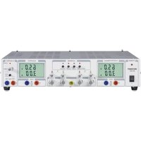
VSP Laboratory Power Unit
GB OPERATING INSTRUCTIONS Page 22 - 39
© Copyright 2010 by Voltcraft®
GB Impressum /legal notice in our operating instructions
These operating instructions are a publication by Voltcraft ^® , Lindenweg 15, D-92242 Hirschau/Germany, Phone +49 180/586 582 7 (www.voltcraft.de).
All rights including translation reserved. Reproduction by any method, e.g. photocopy, microfilming, or the capture in electronic data processing systems require the prior written approval by the editor. Reprinting, also in part, is prohibited.
These operating instructions represent the technical status at the time of printing. Changes in technology and equipment reserved.
© Copyright 2010 by Voltcraft®
© Copyright 2010 by Voltcraft®
© Copyright 2010 by Voltcraft®
01_0510_03/AB

These operating instructions belong with this product. They contain important information for putting it into service and operating it. This should be noted also when this product is passed on to a third party.
Therefore look after these operating instructions for future reference!
A list of contents with the corresponding page numbers can be found in the index on page 22.

Thank you for making the excellent decision of purchasing this Voltcraft® product.
You have acquired a quality product from a brand family which has distinguished itself in the fields of measuring, charging and network technology thanks to its particular expertise and its permanent innovation.
With Voltcraft®, you will be able to cope even with difficult tasks as an ambitious hobbyist or as a professional user. Voltcraft® offers reliable technology with an exceptional cost-performance ratio.
We are positive: starting to work with Voltcraft will also be the beginning of a long, successful relationship.
Enjoy your new Voltcraft® product!
Table of Contents
Introduction 22
Intended Use 23
Operating Elements....24
Safety and Hazard Notices ....25
Functional Description ....27
Commissioning 27
Connecting the Power Cable 27
Unit Installation....27
Setting the Output Voltage of Outputs A and B 28
Setting the Output Current of Outputs A and B 28
Setting the Output Voltage of Output C 29
Connecting a Load 29
Individual Operation ....30
Parallel Operation ....30
Series Operation 32
Serial Operation with Master Control 33
Remote Control Operation "Remote" 34
Sensor Operation "Sense" 35
Disposal 36
Maintenance and Cleaning 36
Exchanging the Fuse 36
Troubleshooting....37
Technical Data ....38
Intended Use
The laboratory power unit unit serves as a potential-free DC voltage source to operate low-voltage consumers. It has three adjustable independent outputs. The outputs A and B can be switched with each other and controlled via buttons. This easily allows you to double the voltage or current. When switching the outputs in series, voltages of >75 V/DC may be generated, which are dangerous to contact. This is why insulated lines/measuring cables must be used for safety reasons as of this voltage. The devices are connected via 4 mm safety sockets.
The output data of the laboratory measuring devices is as follows:
| Item No. | Item name | Output A | Output B | Output C | ||
| 51 | 27 | 73 VSP | 2206 | 0.1 - 20 V/DC | 0.1 - 20 V/DC | 0 - 6 A 0.1 - 6 A max. 1.5A |
| 51 | 27 | 74 VSP | 2403 | 0.1 - 40 V/DC | 0.1 - 40 V/DC | 0 - 3 A 0 - 3 A max. 1.5A |
| 51 | 27 | 75 VSP | 2405 | 0.1 - 40 V/DC | 0.1 - 40 V/DC | 0 - 5 A 0 - 5 A max. 1.5A |
| 51 | 19 | 19 VSP | 2410 | 0.1 - 40 V/DC | 0.1 - 40 V/DC | 0 - 10 A 0 - 10 A max. 1.5A |
| 51 | 27 | 76 VSP | 2653 | 0.1 - 65 V/DC | 0.1 - 65 V/DC | 0 - 3 A 0 - 3 A max. 1.5A |
The voltage and electric current can be adjusted continuously for outputs A and B, as can the voltage of output C. The voltage and current values of output C are displayed via the push of a button on the display of output B.
The settings for current and voltage are made via coarse and fine controls in order to allow fast and precise value settings.
The values are displayed on two separate, concise LC displays.
The output voltage of outputs A and B can be set through an external voltage and kept absolutely stable and load independent using the sense function.
A power limit for constant power operation can be pre-set by pressing a button. You do not require a shorting bar at the output during setting.
The device is overload and short-circuit-proof and contains a safety temperature cut-off.
The laboratory power unit is designed in compliance with protection class 1. It is only approved for connection to shockproof sockets with protective grounding and an alternating current of 230V/AC commonly used in households. The ground potential socket is directly connected with the protective grounding on the mains plug.
Operation under adverse environmental conditions is not permitted. Unfavourable ambient conditions are:
- Moistness or high humidity
- Dust and combustible gases, vapours or solvents
- Thunderstorms or similar conditions such as strong electrostatic fields etc.
Any use other than the one described above damages the product. Moreover, this involves dangers such as e.g. short circuit, fire, electric shock, etc. No part of the product must be modified or rebuilt!
Observe the safety instructions under all circumstances!
Operating Elements
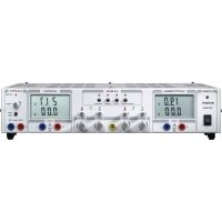
see fold-out page
(1) Power switch for putting the device into operation (I=ON / 0=OFF)
(2) Power indicator
(3) LC display (in short: "display") for output A
(4) Status display output A (CV = constant voltage, OT = overtemperature, CC = current limit)
(5) Selection switch "series tracking" for series switching of output A & B. Both outputs are controlled via the "master" control of output A
(6) Selection switch "series" for serial switching of output A & B (voltage doubling). Separate control.
(7) Selection switch “parallel” for parallel switching of output A & B (electric current doubling). Voltage control for either output is performed by the “master” control for output A.
(8) Selection switch "individual". Each output can be set independently.
(9) Status display output B (CV = constant voltage, OT = overtemperature, CC = current limit)
(10) LC display (in short: "display") for output B
(11) Overload display for output C (current limiting is activated)
(12) Control for the voltage of output C
(13) Push button for voltage and current display of output C on the display of output B (10)
(14) Connection socket negative of output C
(15) Connection socket positive of output C
(16) Connection socket negative of output B
(17) Connection socket positive of output B
(18) Current adjuster for output B (coarse/fine)
(19) Voltage adjuster for output B (coarse/fine)
(20) Connection socket "Ground potential"
(21) Current adjuster for output A (coarse/fine)
(22) Voltage adjuster for output A (coarse/fine)
(23) Connection socket negative of output A
(24) Connection socket positive of output A
(25) Feet on the front side, extendable
(26) Fuse holder for the mains fuse
(27) Grounded low-power connection for mains cable
(28) Terminal strip for remote control and sense connection output B
(29) Terminal strip for remote control and sense connection output A
(30) "C-limit" button for display and setting of the current limitation of output A
(31) "C-limit" button for display and setting of the current limitation of output B
Safety and Hazard Notices

The warranty/guarantee will be void if damage is incurred resulting from non-compliance with these operating instructions. We do not assume liability for damage to property or personal injury caused by improper use or the failure to observe the safety instructions!
This device left the manufacture's factory in a safe and perfect condition.
We kindly request that you as a user observe the safety instructions and warnings contained in this operating manual to preserve this condition and to ensure safe operation! Please pay attention to the following symbols:

An exclamation mark in a triangle shows important information in this user's manual that has to be observed.
The triangle containing a lightning symbol warns of danger of an electric shock or of the impairment of the electrical safety of the device.

The “hand” symbol informs you that there are special tips and hints concerning the operation.

Only to be used in dry indoor areas.

This product has been CE-tested and meets the necessary European guidelines.

Ground potential

Earth wire connection; this screw may not be slackened
The integrated isolating transformer is not short circuit-proof.
The protective gear is switched downstream from the transformer (electric overload and short circuit protection).
Electrical appliances and accessories are no toys and have no place in the hands of children.
On industrial sites, the accident prevention regulations of the association of the industrial workers' society for electrical equipment and utilities must be followed.
Power unit units used at schools, training facilities, do-it-yourself and hobby workshops should not be handled unless supervised by trained, responsible personnel.
Please make sure that your hands, your shoes, your clothing, the floor and the power unit unit are dry.
Live components may be exposed if covers are opened or parts are removed unless this can be done by hand.
Before opening it, disconnect the device from all voltage sources.
Capacitors inside the device may still be charged, even if the device has been disconnected from all voltage sources.
Do not switch the laboratory power pack unit on immediately after it has been taken from a cold to a warm environment. Under adverse conditions, the resulting condensation could destroy the device.
Allow the device to reach room temperature before switching it on.
The plug-in power unit generates heat during operation; ensure that it is adequately ventilated. Do not cover the ventilation apertures of the device!
Do not leave mains power units and connected consumer devices in operation unattended.
Wearing metallic or conductive jewellery, such as necklaces, bracelets, rings etc., while working with power units is not permitted.
The power unit unit is not designed for attaching to humans or animals.
Never expose the device to mechanical stress. Dropping the device even from a low height may damage it! Avoid vibrations and direct sunlight.
If you have reason to believe that the device can no longer be operated safely, disconnect it immediately and make sure it is not unintentionally operated. It can be assumed that safe operation is no longer possible if:
- the device shows visible damage,
- the unit does not operate any longer and
- the unit was stored under unfavourable conditions for a long period of time or
- after it was exposed to extraordinary stress caused by transport.
You should also heed the additional safety instructions in each chapter of these operating instructions as well as in the operating instructions of the connected devices.
Functional Description
The laboratory power unit works with highly developed combinational circuit technology and active PFC (power factor correction). This ensures a stable output voltage and a high degree of effectiveness. The DC outputs are electrically isolated and feature a protective isolation towards the mains voltage. The secondary DC connection is effected via two coloured safety sockets.
The concise dual displays show the voltage and current separately for outputs A and B (V = Volt = unit of electric voltage, A = Ampere = unit of electric current). Output C is displayed via a button on the display of output B. Via light displays the current condition of the power unit is indicated. Various protective mechanisms, e.g. overload protection, current limitation, overheating protection, etc. are built in for secure and reliable operation.
The cooling of the power unit is provided via integrated ventilators. Therefore, ensure sufficient air circulation.
The power unit can set the output voltage and the output current continuously (with output C the voltage only).
Commissioning

The laboratory power unit is not a charger. To charge batteries, use suitable chargers with a charging current cut-off.
During a longer period of operation under nominal load, the surface of the housing will heat up. Attention! Risk of burns! Therefore, make sure that there is adequate ventilation of the power unit and never operate it partly or fully covered to avoid damage.
When connecting a consumer ensure that it is not connected when switched on. A switched on consumer can result in sparks when connecting to the output terminals of the power unit, which in turn can damage the sockets or the connected cables and/or their clamps.
If your power unit is not required, disconnect it from the mains.
Connecting the power cable
Connect the supplied grounding mains cable to the low-power device installation socket (27) on the power unit. Ensure a tight fit.
Connect the power cable to a shockproof mains socket with protective grounding.
Unit installation
Place the laboratory power unit on a stable, level and robust surface. Make sure that ventilation slots in the casing are not covered up.
The front feet of the device can be unfolded for easier reading of the displays. They allow you to put the laboratory power unit into a tilted position.
Setting the output voltage of outputs A and B
Remove any disconnect consumers connected to outputs A and B.
Switch on the mains power unit at the power switch (1). The operating display (2) lights up and the current and voltage display appears on the display.
Press the selection switch "individual" (8). Outputs A and B can be adjusted separately.
Put the current adjustment controls "A" (21 and 18) into central position.
Via the two rotary controls "V coarse" and "V fine", you can set the output voltage for the outputs A and B.
"coarse" Coarse control for fast voltage change
"fine" Fine control for precise voltage selection
In normal mode the device operates in constant voltage mode. This means that the power unit emits a constant, preset output voltage. This operation is indicated with a green status display "CV" (4 or 9).
Setting the current limitation of outputs A and B
Limiting the output current is a protection mechanism to protect the consumer or connection cables. Current limitation can be pre-set at the output without any short circuit. The power unit supplies the maximum current set.
Disconnect consumers connected to outputs A and B.
Switch on the mains power unit at the power switch (1). The operating display (2) lights up and the current and voltage display appears on the display.
Turn the current controls "A coarse" and "A fine" (21 or 19) all the way to the left.
Press the respective "C-limit" button (30 or 31) for outputs A or B and keep this button pressed while setting. The "CC" display is lit during setting. In the "parallel" mode, both buttons must be pressed at once. The respective output is automatically switched off while the "C-limit" button is pressed.
With the two rotary controls "A coarse" and "A fine", you can set the maximum current strength (current limitation). The LED display "CC" is lit when as the current limitation is active.
"coarse" Coarse control for fast current setting
"fine" Fine control for precise current setting
Let go of the "C-limit" key after making your settings. The display shows the actual current (for unloaded output: 0.00 A). The status display "CV" is lit.

If the preset current is reached in normal operation, the power unit switches to current limitation mode and reduces the voltage value. This operation is indicated with a red status display "CC" (11).
Setting the output voltage of output C
Output C can be used independently of the set operating mode (series-tracking/series/parallel/individual).
Remove connected consumers from output C.
Switch on the mains power unit at the power switch (1). The operating display (2) lights up and the current and voltage display appears on the display.
Press the button "show value" (13) and keep this depressed while setting the voltage. The display of output B shows the voltage and current of output C.
With the rotary control "V-adjust" (12), you can set the output voltage for output C.
After setting the voltage, let go of the button (13) again.

A fixed current limitation of approx. 1.5 A is set for output C, which cannot be changed. When this current limit is reached, the red indicator “overload” (11) lights up.
You can check the corresponding voltage and current values at any time by pressing the button "show value" (13).
Connecting a Consumer

When connecting a consumer, make sure that it is connected to the power unit when switched off. The maximum current consumption of the device to be connected must not exceed the capacity indicated in the technical specifications.
For series connection of the outputs A and B or several power units, voltages > 75 VDC are generated, whose contact can be fatal. As of this voltage, you may only use insulated accessories.
Avoid the use of non-insulated metallic cables and contacts. All of these spots must be covered with suitable, flame-resistant insulation materials or by means of other measures, which serve to prevent direct contact and short circuits.
Ensure a sufficient cable diameter for the intended current.
Individual operation
In individual mode, you can connect and adjust both outputs independently of each other. This function allows operation with 2 different output voltages.
Disconnect consumers connected to outputs A and B.
Switch on the mains power unit at the power switch (1). The operating display (2) lights up and the current and voltage display appears on the display.
Press the selection switch "individual" (8). The red indicator above the switch is lit. Outputs A and B can be adjusted separately.
Set the parameters according to your specifications as described in the chapter "Commissioning".
Verify again that the output voltage has been set correctly.
Connect the positive terminal (+) of the consumer with the red socket “+” and the negative terminal (-) of the consumer with the blue socket “-” of the respective output (A/B).

text_image
A-OUTPUT + - B-OUTPUT + -Now you can switch on the connected consumer.
The current consumption of the connected consumer is displayed in Ampere (A) in the power display.
Parallel operation
In parallel mode, you can use the outputs A and B to double the current. In this mode, the outputs A and B are switched parallel internally. No external switching is required for up to 10 A.
Disconnect consumers connected to outputs A and B.
Switch on the mains power unit at the power switch (1). The operating display (2) lights up and the current and voltage display appears on the display.
Press the selection switch “parallel” (7). The red indicator above the switch is lit.
Set the parameters according to your specifications as described in the chapter "Commissioning". The voltage settings are made only through output A (master). The current control for output B is deactivated
The current settings are made in combination with outputs A and B. The sum of both current indicators equals the output current.
Verify again that the output voltage has been set correctly.
Connection with a total output current of <10A:
Connect the positive terminal (+) of the consumer with the red socket "+" and the negative terminal (-) of the consumer with the blue socket "-" of output A.
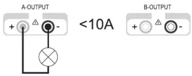
text_image
A-OUTPUT + △ - <10A B-OUTPUT + △ -Connection with a total output current of >10A:
Connect the positive terminal (+) of the consumer with the red socket "+" and the negative terminal (-) of the consumer with the blue socket "-" of outputs A and B.
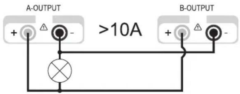
text_image
A-OUTPUT >10A B-OUTPUT
The double connection increases the conductor cross-section and reduces the voltage loss in the lines. Use connection lines of the same length and the same conductor cross-section.
Now you can switch on the connected consumer.
The current consumption of the connected consumer is displayed in Ampere (A) in the power display. The sum of both current displays corresponds to the output current.
Series operation
In serial mode, you can use the outputs A and B to double the voltage. In this mode, the outputs A and B are switched in series internally. Additional external switching is not required.
Disconnect consumers connected to outputs A and B.
Switch on the mains power unit at the power switch (1). The operating display (2) lights up and the current and voltage display appears on the display.
Press the selection switch "series" (6). The red indicator above the switch is lit.
Set the parameters according to your specifications as described in the chapter "Commissioning". The current settings are made in combination with outputs A and B. The sum of both current indicators (A and B) equals the output current.
The current settings can be made through outputs A or B.
Verify again that the output voltage has been set correctly.
Connect the positive terminal (+) of the consumer with the red socket “+” (24) of output A and the negative terminal (-) with the blue socket “-” (16) of output B.
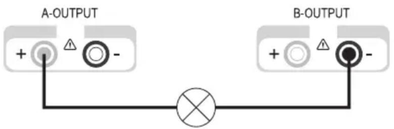
text_image
A-OUTPUT + - B-OUTPUT + -Now you can switch on the connected consumer.
The current consumption of the connected consumer is indicated on both displays simultaneously. The current of one display corresponds to the output current.

The current setting controls of both outputs may not be located in the minimum position (left stop), otherwise it is not possible to use the entire setting range for the voltage.
Serial operation with master control
Just like normal serial mode, this mode serves to double the voltage of outputs A and B. The difference to normal serial mode is the control. Voltage and current are controlled exclusively by the adjustment controls of output A. Outputs A and B are switched in series internally. Additional external switching is not required.
Disconnect consumers connected to outputs A and B.
Switch on the power unit at the power switch (1). The operating display (2) lights up and the current and voltage display appears on the display.
Press the selection switch "series tracking" (5). The red indicator above the switch is lit.
Set the parameters according to your specifications as described in the chapter “Commissioning”. The voltage and current settings are made only through the control of output A. The sum of both voltage indicators (A and B) equals the output voltage.
Verify again that the output voltage has been set correctly.
Connect the positive terminal (+) of the consumer with the red socket “+” (24) of output A and the negative terminal (-) with the blue socket “-” (16) of output B.
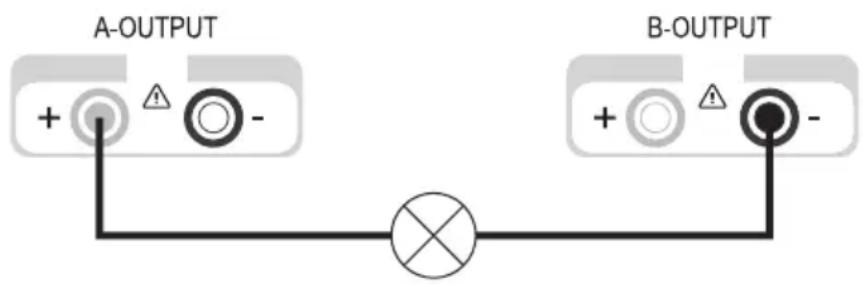
text_image
A-OUTPUT + - B-OUTPUT + -Now you can switch on the connected consumer.
The current consumption of the connected consumer is indicated on both displays simultaneously. The current of one display corresponds to the output current.

The current setting controls of both outputs may not be located in the minimum position (left stop), otherwise it is not possible to use the entire setting range for the voltage.
Remote control operation "remote"
The laboratory power unit can be remote controlled via external direct current. The control voltage is 0 - 2.3 V/DC and controls the entire adjustment range of the corresponding output proportionally. Remote control operation is only possible in individual and serial mode.

The current setting controls of both outputs may not be located in the minimum position (left stop), otherwise it is not possible to use the entire setting range for the voltage. For remote control operation, the voltage controls must be set to maximum to provide the full adjustment range.
Disconnect consumers connected to outputs A and B and turn the power unit off.
On the back of the device, remove the plastic cover of the respective terminal strip. Terminal strip (28) for output A, terminal strip (29) for output B.
Remove the shorting bar between the clamps "V ref OUT" and "V ref IN"
Connect the positive terminal of the external control voltage to the clamps "V ref IN" and the negative terminal to the clamp "COMMON" an.
Reattach the plastic cover to the terminal strip.
Switch on the power unit at the power switch (1). The operating display (2) lights up and the current and voltage display appears on the display.
Operate the selection switch for individual or serial mode. The red indicator above the switch is lit.
Set the current limit according to your specifications as described in the chapter "Commissioning". Now the voltage is only set via the external control voltage.
Verify again that the output voltage has been set correctly.
Connect the positive terminal (+) of the consumer with the red socket “+” and the negative terminal (-) of the consumer with the blue socket “-” of the respective output.
Now you can switch on the connected consumer.

For normal control through the controls on the device, you have to replace the shorting bar at the back between the "V ref OUT" and "V ref IN" clamps.

text_image
OUTPUT V ref OUT V ref IN COMMON 0 - 2,3 V/DC (+) SENSE OUT (+) SENSE IN (-) SENSE OUT (-) SENSE INSensor operation "sense"
The sensor operation “sense” allows the precise voltage setting directly on the consumer. This reliably compensates a possible voltage drop via the connection cables. Sensor operation is only possible in individual mode.

The current setting controls of both outputs may not be located in the minimum position (left stop), otherwise it is not possible to use the entire setting range for the voltage.
Disconnect consumers connected to outputs A and B and turn the power unit off.
On the back of the device, remove the plastic cover of the respective terminal strip. Terminal strip (28) for output A, terminal strip (29) for output B.
Remove the two shorting bars between the clamps “(+) SENSE OUT” and “(+) SENSE IN” as well as “(-) SENSE OUT” and “(-) SENSE IN”.
Connect the consumer with the corresponding output sockets on the power unit observing the right polarity.
Connect the sensor cable from the connection clamps of the consumer with the sensor input on the power unit observing the right polarity. The positive lead must be connected to the clamp “(+) SENSE IN” and the negative lead to the clamp “(-) SENSE IN”.
Reattach the plastic cover to the terminal strip.
Switch on the power unit at the power switch (1). The operating display (2) lights up and the current and voltage display appears on the display.
Push the selection switch for individual mode. The red indicator above the switch is lit.
Set the parameters according to your specifications as described in the chapter "Commissioning".
Verify again that the output voltage has been set correctly.
Now you can switch on the connected consumer.
For normal operation without remote sensing, the shorting bars must be replaced.

When disconnecting the consumer, always disconnect the supply cables first or turn the laboratory power unit off before disconnecting the sensor cables. If you do not observe this sequence, the output voltage may rise to maximum and damage your consumer.
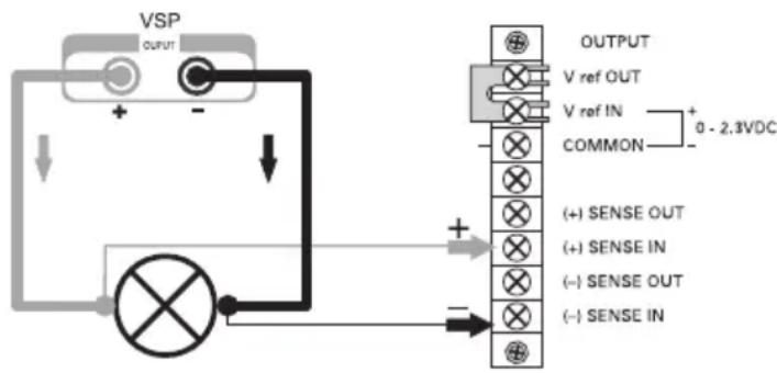
text_image
VSP OUTPUT V ref OUT V ref IN COMMON 0 - 2.3VDC (+) SENSE OUT (+) SENSE IN (-) SENSE OUT (-) SENSE INDisposal
Old electronic devices are hazardous waste and should not be disposed of in the household waste. At the end of its service life, dispose of the product at the collection point of your community according to the relevant statutory regulations. Disposing of flat batteries in the household waste is prohibited.
Maintenance and Cleaning
Apart from an occasional cleaning or exchanging the fuse, this laboratory power unit is maintenance-free. Use a clean, lint-free, antistatic and dry cloth to clean the device. Do not use any abrasive or chemical agents or detergents containing solvents.
Exchanging the fuse
If it is no longer possible to switch on the laboratory power unit, the rear mains fuse (26) is probably defective.
Proceed as follows to replace the mains fuse:
Switch off the power unit unit and remove all connecting cables from the unit. Pull the mains plug from the mains socket.
Using a suitable screwdriver, depress the fuse holder (9) on the rear side a little, and remove it with a quarter-turn anti-clockwise rotation (bayonet cap).
Replace the defective fuse with a new fine-wire fuse (5 x 20 mm) of the same type and rated current. The fuse value is listed in the technical data.
While pushing, screw the fuse plug clockwise back into the fuse holder.
Troubleshooting
By purchasing the laboratory power unit unit, you have acquired a product that is reliable and operationally safe.
Nevertheless, problems or faults may occur.
For this reason we want to describe how to troubleshoot potential malfunctions:

Always adhere to the safety instructions!
| Error Possible cause | |
| The power unit cannot Does the operation display light up on the power unit (2)?be switched on. Check the mains voltage (you may also want to check the mains fuse in the device or the line circuit breaker). | |
| Connected consumer devices Is the voltage set correctly?do not work. Is the polarity correct?Check the technical data of the consumers. | |
| The “OT” indicator is lit The power unit is overloaded and overheated.Leave the device on and cool down without load. | |
| The “CC” indicator is lit. Constant current operationThe preset current was exceeded. Check power consumption on your consumer and increase the current limitation on your power unit, if applicable. | |
| The “CV” indicator is lit Constant voltage operationThe power unit works normally. The output provides the constant voltage set. | |
Regularly check the technical safety of the device e.g. for damaged housing etc.

Any other repair work must always be carried out by a specialist familiar with the hazards involved and with the relevant regulations. Unauthorized modifications or repairs to the device invalidate the warranty/guarantee. Fuses are replacement parts and not covered by the warranty/guarantee!
Technical Data
| VSP 2206 | VSP 2403 | VSP 2405 | VSP 2410 | VSP 2653 | |
| Output power 249 VA 249 | VA 409 VA 809 | VA 399 VA | |||
| Output voltage 0.1 - 20 V DC-Output A | 0.1 - 40 V 0.1 - | 40 V 0.1 - 40 V | 0.1 - 65 V | ||
| Output current 0 - 6 A 0 - 3 A 0 - 5 A Output A | A 0 - 5 A | 0 - 10 A | 0 - 3 A | ||
| Output voltage 0.1 - 20 V DC-Output B | 0.1 - 40 V 0.1 - | 40 V 0.1 - 40 V | 0.1 - 65 V | ||
| Output current 0 - 6 A 0 - 3 A 0 - 5 A Output B | A 0 - 5 A | 0 - 10 A | 0 - 3 A | ||
| Output voltage DC-Output C | 0.1 - 6 V | ||||
| Output current Output C | max. 1.5 A | ||||
| Residual ripple at nominal load | |||||
| Output A of Vmax | < 0,025% | < 0,025% | < 0,0125% | < 0,025% | < 0,0125% |
| Output B of Vmax | < 0,025% | < 0,025% | < 0,0125% | < 0,025% | < 0,0125% |
| Output C of Vmax | < 0,005% | < 0,005% | < 0,005% | < 0,006% | < 0,005% |
| Voltage Control response at 100% Load change | < 0,04% (Vmax) (Vmax) | < 0,04% (Vmax) | < 0,03% (Vmax) (Vmax) | < 0,04% | < 0,03% |
| Voltage Control response at 20% Mains fluctuation | < 0,005% (Vmax) (Vmax) | < 0,005% (Vmax) | < 0,0025% (Vmax) (Vmax) | < 0,005% | < 0,0025% |
| Current control behaviour at 100% Load change | <5 mA | <6 mA | <6 mA | <5 mA | <5 mA |
| Current control behaviour at 20% mains fluctuation | <5 mA | <6 mA | <6 mA | <5 mA | <5 mA |
| Operating Voltage | 230 V/AC (±20%) 47 - 53 Hz | ||||
| Power consumption 350 VA (max.) | A 350 VA 500 | VA 1000 VA | 500 VA | ||
| Mains fuse slow-blow (5 x 20 mm) | T2.5A/250V | T2.5A/250V | T3,15A/250V | T6.3A/250V | T3.15A/250V |
| Operating temperature | 0 to +40°C | ||||
| Rel. air humidity max. 80%, non-condensing | |||||
| Protection class 1 | |||||
| Mains Connection Low-power device installation plug, IEC 320 C14 | |||||
| Weight 7.3 kg 7.5 kg 7.3 kg | |||||
| Dimensions 437 x 88 x 340(W x H x D) mm | |||||

Introduction
Chère cliente, cher client,