
GD 10 E - Heating Güde - Free user manual and instructions
Find the device manual for free GD 10 E Güde in PDF.

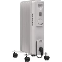
| Product type | Forced air individual heater |
| Brand | Güde |
| Model | GD 10 E |
| Heat output | 10 kW (35,000 Btu/h) |
| Recommended fuel | Kerosene or No. 1 fuel oil |
| Tank capacity | 15 liters |
| Fuel consumption | 1.1 L/h |
| Supply voltage | 220-240 V / 50 Hz (single-phase) |
| Rated current | 0.8 A |
| Air flow rate | 280 m³/h |
| Motor speed | 1425 rpm |
| Ignition type | Electronic with ignition control |
| Flame detection | Photocell |
| Protection | Automatic shutdown in case of flame failure |
| Required ventilation | At least 2800 cm² of fresh outdoor air per 25,000 kcal/h |
| Minimum distance to combustible materials | Outlet: 250 cm; sides, top, and rear: 125 cm |
| Filters | Air inlet filter, air outlet filter, lint filter, fuel filter |
| Tank maintenance | Rinse every 150-200 hours of operation |
| Filter replacement | Outlet and lint filters: every 500 hours or once a year |
| Air inlet filter cleaning | With soapy water every 500 hours |
| Nozzle cleaning | Blow with compressed air if clogged |
| Recommended extension cord | Up to 30 m: gauge 1.0 mm²; from 30 to 60 m: gauge 1.5 mm² |
| Wheel mounting (29 kW models) | Not applicable to this model (GD 10 E without wheels) |
| Weight and dimensions | Not specified in the manual |
Frequently Asked Questions - GD 10 E Güde
User questions about GD 10 E Güde
0 question about this device. Answer the ones you know or ask your own.
Ask a new question about this device
Download the instructions for your Heating in PDF format for free! Find your manual GD 10 E - Güde and take your electronic device back in hand. On this page are published all the documents necessary for the use of your device. GD 10 E by Güde.
USER MANUAL GD 10 E Güde
Portable forced air heaters

natural_image
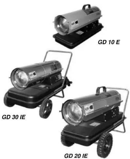
Four different portable lighting units labeled GD 10 E, GD 30 IE, GD 20 IE, and an unlabeled black device (no text or symbols on the devices themselves)# 85090, 85091, 85092
CE
Güde GmbH & Co. KG
Birkichstraße 6
D-74549 Wolpertshausen
www.guede.com
Güde Scandinavia A/S
Engelsholmvej 33
DK-8900 Randers
www.guede.com
Guede Czech s.r.o.
P.O. Box 8
Poèernická 120
CZ-360 05 Karlovy Vary
www.unicore.cz
GÜDE Slovakia s.r.o
Podtúreò-Roveò 208
SK-033 01 Liptovský
Hrádok
www.guede.com
SPECIFICATIONS - SPÉCIFICATIONS - TECHNISCHE DATEN - TECHNISCHE GEGEVENS - DATI TECNICI - ASPECIFICACIONES - SPECIFIKATIONER - TEKNISET TIEDOT - SPECIFIKATIONER - SPESIFIKASJONER - SPECYFIKACJE - TEXНИЧЕСКИЕ
ХАРАКТЕРИСТИКИ - МÜSZAKI ADATOK - TECHNICKÉ ÚDAJE - SPECIFIKACIJOS - TEHNILISED ANDMED - TEHNISKIE DATI
| GD 10 E GD | 20 IE GD 30 IE | ||
| Max power - Puissance thermique max. - Max Wärmeleistung - Max Vermogen - Potenza termica max - Potencia térmica max - Värmestyrka max - Enimmäislämpöteho - Maks. Termisk Effekt - Maksimal varmeeffekt - Wydajność - Номинальная выходная мощность - Teljesítmény - Jmenovitá vákon - Nominalioji galia - Väljundvõimsus - Izejas jauda | 10 kW35.000 Btu/h | 20 kW70.000 Btu/h | 29 kW100.000 Btu/h |
| Fuel - Combustible - Kraftstoff - Brandstof - Combustibile - Combustible - Bränsle - Polttoaine - Brændstof - Brennstoff - Paliwo - Топливо - Fütőolaj - Palivo - Kuras - Kütus - Kurinämais | diesel/ kerosene | diesel/ kerosene | diesel/ kerosene |
| Fuel Tank Capacity - Capacité Du Reservoir Fuel - Kraftstofftank / Fassungsvermögen - Tankinhoud - Capacità serbatoio - Capacidad del tanque de combustible - Tankstorlek - Polttoainesäliön tilavuus - Tankkapacitet i liter - Størrelse på brennstofftanken - Pojemność zbiornika paliwa - Емкость топливного бака - Fütőolajtartály térfogata - Kapacita palivové nádrže - Kuro talpyklos talpa - Kütusepaagi maht - Kurinämä tvertnes | 15 Lt 19 Lt | 44 Lt | |
| Fuel Consumption - Consommation Fuel - Kraftstoffverbrauch - Brandstofverbruik - Consumo di combustibile - Consumo de combustible - Bränsleförbrukning - Polttoaineenkulutus - Petroleumsforbrug - Brennstofforbruk - Zuzycie paliwa - Pacxod топлива - Fütőolaj fogyasztás - Spotreba paliva - Kuro išeikvojimas - Kütusekulu - Kurinämä patērinš | 0,86 Kg/h 1,7 | Kg/h 2,45 Kg/h | |
| Electric Requirements - Tension-V - Elektrischer Anschluß - Netvoeding - Alimentazione elettrica - Requisitos eléctricos - Elektrisk ström - Sähkövirta - El-type - Elektriske krav - Wymagania odnosnie zasilania - Электропитание - Villamos csatlakozás - Potrebné elektrické napetí - Elektros sistemos priežiūros reikalavimai - Nõuded elektrisüsteemile - Prasības elektriskajai sistēmai | 220-240 V / 50 Hz | 220-240 V / 50 Hz | 220-240 V / 50 Hz |
| Amperage - Ampérage - Stromstärke - Stroomsterkte - Amperaggio - Amperaje - Strömstyrka, ampere - Ampeerikulutus - Strömstyrke - Strömstyrke - Pobór pradu - Tok - Áramfelvé - Potrebná elektrická proud - Sroves stiprumas amperais - Voolutugevus - Barošanas spriegums | 0,8 A 1 A | ,2 A | |
| Hot Air Output - Débit D'air - Heißluftausstoß - Blaasvermogen hete lucht - Portata d'aria - Salida de aire caliente - Hetluftsutsläpp - Kuumailmateho - Varmluftmængde i m3 i minuttet - Varmluftskapasitet - Wydajnosc cieplego powietrza - Выход горячего воздуха - Meleg levegő kibocsátás - Vástup horkého vzduchu - Karšto oro našumas - Kuuma õhu tootlikkus - Karstā gaisa jauda | 280 m^3/h 400 | m^3/h 800 m^3/h | |
| RPM - Régime Moteur - U/min - Toerental - Giri al minuto - Velocidad - RPM - Kierrosluku - Omdrejningstal i minuttet,el-motor - Obroty na minute - Скорость вращения электродвигателя - Fordulatszám - Otáčky za minutu - Apsisukimai per minutę - pööret minutis - apgriezieni minūtē | 1425 2850 | 2850 |
Bedienungsanleitung
Ölheizgebläse

natural_image
Four different portable air purifiers labeled GD 10 E, GD 30 IE, GD 20 IE, and a plain black base (no text or symbols on the purifiers themselves)# 85090, 85091, 85092
CE
Güde GmbH & Co. KG
Birkichstraße 6
D-74549 Wolpertshausen
Güde Scandinavia A/S
Engelsholmvej 33
DK-8900 Randers
Guede Czech s.r.o.
P.O. Box 8
Poèernická 120
CZ-360 05 Karlovy Vary
GÜDE Slovakia s.r.o
Podtúreò-Roveò 208
SK-033 01 Liptovský
Hrádok
www.guede.com
www.guede.com
www.unicore.cz
www.guede.com
SICHERHEITS
INFORMATIONEN

WARNHINWEISE
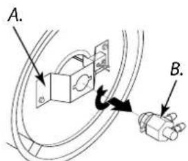
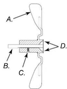
(siehe Abb. 11)
A. Brennkammer
B. Düsen-/Adapter-Bau- gruppe
natural_image
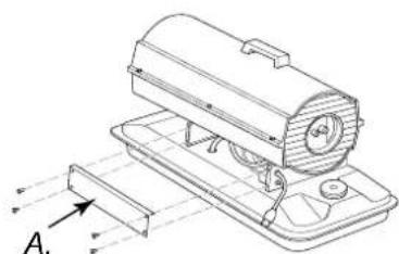
Technical line drawing of a mechanical device with no visible text or symbolsA. Seitenabdeckung
TECHNISCHE DATEN
That the following Appliance complies with the appropriate basic safety and health requirements of the EC Directive based on its design and type, as brought into circulation by us.
In a case of alternation of the machine, not agreed upon by us, this declaration will lose its validity.
Portable forced air heater
natural_image
Four different portable lighting machines labeled GD 10 E, GD 30 IE, GD 20 IE, and an unlabeled black base (no text or symbols on the devices themselves)# 85090, 85091, 85092
CE
Güde GmbH & Co. KG
Birkichstraße 6
D-74549 Wolpertshausen
Güde Scandinavia A/S
Engelsholmvej 33
DK-8900 Randers
Guede Czech s.r.o.
P.O. Box 8
Poèernická 120
CZ-360 05 Karlovy Vary
GÜDE Slovakia s.r.o
Podtúreò-Roveò 208
SK-033 01 Liptovský
Hrádok
www.guede.com
www.guede.com
www.unicore.cz
www.guede.com
SAFETY INFORMATION
⚠️ WARNINGS
IMPORTANT: Read this owner's manual carefully and completely before trying to assemble, operate, or service this heater. Improper use of this heater can cause serious injury or death from burns, fi re, explosion, electric shock, and carbon monoxide poisoning.

DANGER: Carbon monoxide poisoning may lead to n!
Carbon Monoxide Poisoning: Early sign of carbon monoxide poisoning resemble the flu, with headaches, dizziness, and/or nausea. If you have these signs, the heater may not be working properly. Get fresh air at once! Have heater serviced. Some people are more affected by carbon monoxide than others. These include pregnant women, persons with heart or lung disease or anemia, those under the influence of alcohol, and those at high altitudes.
Make certain you read and understand all warnings. Keep this manual for reference. It is your guide to safe and proper operation of this heater.
- Use only kerosene or No. 1 fuel oil to avoid risk of fire or explosion. Never use gasoline, naphtha, paint thinners, alcohol, or other highly fl ammable fuels.
- Fueling
a) Personnel involved with fueling shall be qualified and thoroughly familiar with the manufacturer's instructions and applicable regulations regarding the safe fueling of heating units.
b) Only the type of fuel specified on the heater's data plate shall be used.
c) All flame, including the pilot light, if any, shall be extinguished and the heater allowed to cool, prior to fueling.
d) During fueling, all fuel lines and fuelline connections shall be inspected for leaks. Any leaks shall be repaired prior to returning the heater to service.
e) At no time shall more than one day's supply of heater fuel be stored inside a building in the vicinity of the heater. Bulk fuel storage shall be outside the structure.
f) All fuel storage shall be located a minimum of 762cm (25 feet) from heaters, torches, welding equipment, and similar sources of ignition (exception: the fuel reservoir integral with the heater unit).
g) Whenever possible, fuel storage shall be confined to areas where fl oor penetrations do not permit fuel to drip onto or be ignited by a fi re at lower elevation.
h) Fuel storage shall be in accordance with the authority having jurisdiction.
- Never use heater where gasoline, paint thinner, or other highly flammable vapors are present.
- Follow all local ordinances and codes when using heater.
- Heaters used in the vicinity of tarpaulins, canvas, or similar enclosure materials shall be located a safe distance from such materials. The recommended minimum safe distance is
304.8cm (10 feet). It is further recommended that these enclosure materials be of a fire retardant nature. These enclosure materials shall be securely fastened to prevent them from igniting or from upsetting the heater due to wind action.
- Use only in well-vented areas. Before using heater, provide at least a 2800 square cm (three-square-foot) opening of fresh, outside air for each 29 kw (100,000 Btu/Hr) of rating.
- Use only in places free of flammable vapors or high dust content.
- Use only the electrical voltage and frequency specified on model plate.
- Use only a three-prong, grounded extension cord.
- Minimum heater clearances from combustibles: Outlet: 250 cm (8 Ft.) Sides, Top, and Rear: 125 cm (4 Ft.)
- Locate heater on a stable and level surface if heater is hot or running or a fire may occur.
- When moving or storing heater, keep heater in a level position or fuel spillage may occur.
- Keep children and animals away from heater.
- Unplug heater when not in use.
- When used with thermostat, heater may start anytime.
- Never use heater in living or sleeping areas.
- Never block air inlet (rear) or air outlet (front) of heater.
- Never move, handle, refuel, or service a hot, operating, or plugged-in heater.
- Never attach duct work to front or rear of heater.
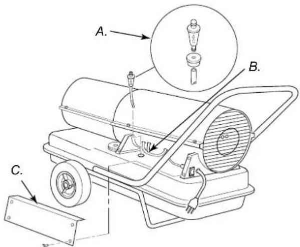
PRODUCT IDENTIFICATION
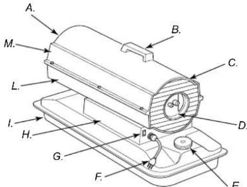
Figure 1 - Model 35.000 e 70.000 Btu/Hr

Figure 2 - Model 100.000 Btu/Hr
(see figure 1, e 2)
A. Hot Air Outlet, B. Handle, C. Fan Guard, D. Air Filter End Cover, E. Fuel Cap, F. Power Cord, G. ON/OFF Switch with Light, H. Side Cover, I. Fuel Tank, L. Lower Shell, M. Upper Shell.
UNPACKING
- Remove all packing items applied to heater for shipment.
- Remove all items from carton.
- Check items for any shipping damage. If heater is damaged, promptly inform dealer where you bought heater.
FUELS
WARNING: Use only kerosene or No. 1 fuel oil to avoid risk of fi re or explosion. Never use gasoline, naphtha paint thinners, alcohol or other highly fl ammable fuels.
Do not use heavy fuels such as No. 2 fuel oil or No. 2 Diesel. Using heavy fuels will result in:
• clogged fuel filter and nozzle
- use of non-toxic anti-icer in fuel during very cold weather
IMPORTANT: Use a KEROSENE ONLY container. Be sure storage container is clean. Foreign matter such as rust, dirt, or water will cause the flame-out control to shut down heater. Foreign matter may also require you to clean fuel system often.
ASSEMBLY
(for 100.000 Btu/Hr models only)
These models are furnished with wheels and handles. Wheels, handles, and the mounting hardware are found in the shipping carton.
Tools Needed
• Medium Phillips Screwdriver
• 3/8" Open or Adjustable Wrench
- Hammer
- Slide axle through wheel support frame. Install wheels on axle. IMPORTANT: When installing wheels, point extended hub of wheels toward wheel support frame (see Figure 3).
- Place cap nuts on axle ends. Gently tap with hammer to secure.
- Place heater on wheel support frame. Make sure air inlet end (rear) of heater is over wheels. Line up holes on fuel tank fl ange with holes on wheel support frame.
- Place front handle and rear handle on top of fuel tank flange. Insert screws through handles, fuel tank fl ange, and wheel support frame. Attach nut finger tight after each screw is inserted
- After all screws are inserted, tighten nuts firmly.
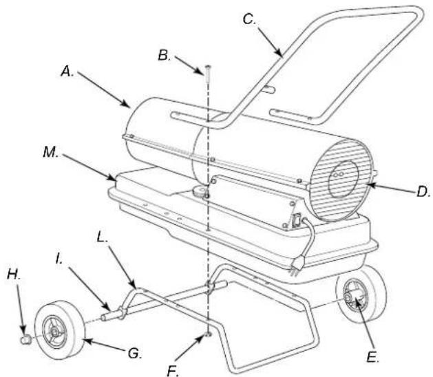
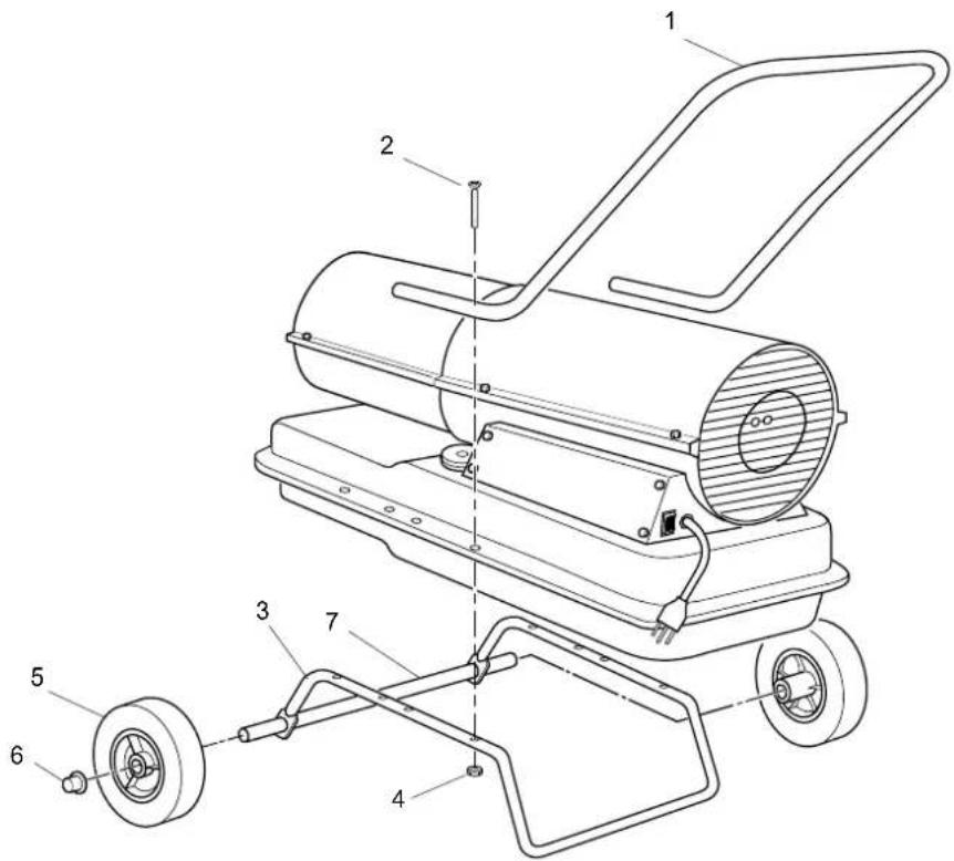
Figure 3 – Wheel and Handle Assembly.
A. Hot Air Outlet, B. Screw, C. Front Handle, D. Rear Handle, E. Air Inlet, F. Extended Hub, G. Axle, H. Wheel, I. Nut, L. Cap Nut, M. Wheel Support Frame, N. Fuel Tank Flange.
VENTILATION
WARNING: Follow the minimum fresh, outside air ventilation requirements. If proper fresh, outside air ventilation is not provided, carbon monoxide poisoning can occur. Provide proper fresh, outside air ventilation before running heater.
Provide a fresh air opening of at least 2800 square cm (three square feet) for each 29kw (100,000 Btu/Hr) rating. Provide extra fresh air if more heaters are being used..
Example: A 44kw (150,000 Btu/Hr) heater requires one of the following:
- a two-car garage door [4.9 meter (16 feet) opening] raised 9 cm (3.5 inches).
- a single-car garage door [2.75 meter (9 feet) opening] raised 15.25 cm (6 inches).
- two, 76 cm (30 inch) windows raised 28 cm (11 inches).
THEORY OF OPERATION
The Fuel System: The air pump forces air through the air line. The air is then pushed through the burner head nozzle. This air causes fuel to lift from the tank. A fine mist of fuel is sprayed into the combustion chamber.
The Air System: The motor turns the fan. The fan pushes air into and around the combustion chamber. This air is heated and provides a stream of clean, hot air.
The Ignition System: The ignition control assembly provides power to the ignitor. This ignites the fuel/air mixture in the combustion chamber.
The Flame-Out Control System: This system causes the heater to shut down if the flame goes out.
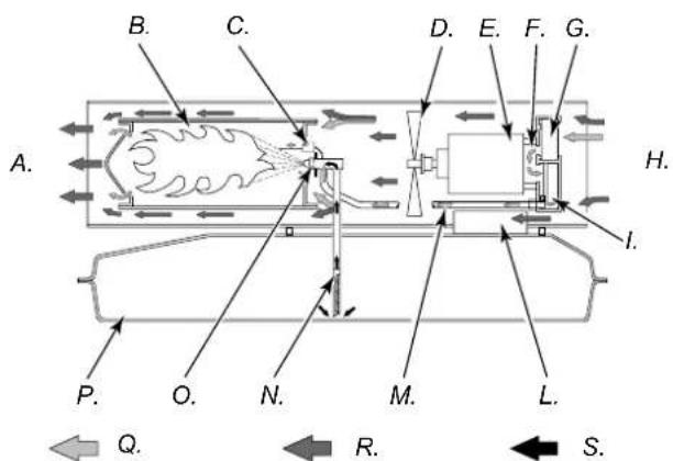
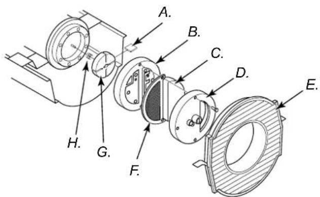
Figure 4 – Cross Section operational view.
(see figure 4)
A. Clean Heated Air Out, B. Combustion Chamber, C. Ignitor, D. Fan, E. Motor, F. Air Pump, G. Air Intake Filter, H. Cool Air In, I. Air Output Filter, L. Ignition Control Assembly, M. Air Line To Burner, N. Fuel Filter, O. Nozzle, P. Fuel Tank, Q. Air For Fuel System, R. Air For Combustion And Heating, S. Fuel.
OPERATION
WARNING: Review and understand the warnings in the Safety Information section, page 2. They are needed to safely operate this heater. Follow all local codes when using this heater.
TO START HEATER
- Follow all ventilation and safety information.
- Fill fuel tank with kerosene or No. 1 fuel oil.
- Attach fuel cap.
- Plug power cord of heater into standard 220-240V/50 Hz, grounded (earthed) outlet. Use an extension cord if needed. Use only a three-prong, grounded (earthed) extension cord.
Extension cord wire size requirements:
Up to 30 meters (100 feet) long, use 1.0 mm2 (16 AWG) conductor. 30 to 61 meters (101 to 200 feet) long, use 1.5 mm2 (14 AWG) conductor.
Push ON/OFF switch to ON (|) position and heater should start in 5 seconds. If heater does not start, see Troubleshooting (page 7).
TO STOP HEATER
Push ON/OFF switch to OFF (O) position.
TO RESET HEATER
- Push ON/OFF switch to OFF (O) position and wait 10 seconds (2 minutes if heater has been running).
- Repeat steps under To Start Heater.
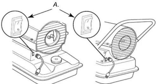
Figure 5-6 – ON/OFF Switch, Models 10 KW, 20 KW, 29 KW and 44 KW.
(see figure 5 e 6)
A. ON/OFF Switch with Light.
STORING, TRANSPORTING, OR SHIPPING
Note: If shipping, transport companies require fuel tanks to be empty.
- Drain fuel tank.
Note: Some models have drain plug on underside of fuel tank. If so, remove drain plug to drain all fuel. If heater does not have drain plug, drain fuel through fuel cap opening. Be sure all fuel is removed.
-
Replace drain plug if provided.
-
If any debris is noted in old fuel, add 1 or 2 quarts of clean kerosene to tank, stir, and drain again. This will prevent excess debris from clogging fi Iters during future use.
-
Replace fuel cap or drain plug. Properly dispose of old and dirty fuel. Check with local automotive service stations that recycle oil.
-
If storing, store heater in dry place. Make sure storage place is free of dust and corrosive fumes.
IMPORTANT: Do not store kerosene over summer months for use during next heating season. Using old fuel could damage heater.
PREVENTATIVE MAINTENANCE SCHEDULE
WARNING: Never service heater while it is plugged in, operating, or hot. Severe burns and electrical shock can occur.
Item How Often How To
| Fuel tank Flush every 150-200 hours of operation or as needed | See Storing, Transporting,or Shipping | |
| Air output andlint filters | Replace every 500 hours of operation or once a year | See Air Output, Air Intake, and Lint Filters, page 8 |
| Air intake fi Iter Wash and dry with soap and water every 500 hours of operation or as needed | See Air Output, Air Intake, and Lint Filters, page 8 | |
| Fuel filter | Clean twice a heating season or as needed | See Fuel Filter, page 6 |
| Ignitor No maintenance required | ||
| Fan blades Clean every season or as needed See Fan, page 11 | ||
| Motor Not required/permanently lubricated | ||
TROUBLESHOOTING
WARNING: Never service heater while it is plugged in, operating, or hot. Severe burns and electrical shock can occur.
HEATER WITH FUSED OR NON-FUSED IGNITION CONTROL ASSEMBLY
ATTENTION: The ignition control has built-in protection against current overloads. Use the light in the ON/OFF switch to troubleshoot the fault condition.
FAULT CONDITION POSSIBLE CAUSE
REMEDY
| Motor does not start fi ve seconds after heater is plugged in (ON/OFF switch light remains on) | 1. Bad electrical connection between motor and ignition control assembly or ignition control assembly and power cord | 1. Check all electrical connections. See Wiring Diagram, page 17 |
| WARNING: High voltage! | ||
| 2. Binding pump rotor | 2. If fan does not turn freely, see Pump Rotor, page 10 | |
| 3. Defective ignition control assembly | 3. Replace ignition control assembly | |
| 4. Defective motor | 4. Replace motor | |
| Motor starts and runs but heater does not ignite (ON/OFF switch light remains on) | 1. No fuel in tank | 1. Fill tank with kerosene |
| 2. Pump pressure incorrect | 2. See Pump Pressure Adjustment, page 8 | |
| 3. Dirty fuel filter | 3. See Fuel Filter, page 6 | |
| 4. Obstruction in nozzle assembly | 4. See Nozzle Assembly, page 8 | |
| 5. Water in fuel tank | 5. Drain and flush fuel tank with clean kerosene. See Storing, Transporting, or Shipping, page 4 | |
| WARNING: High voltage! | ||
| 6. Bad electrical connection between ignitor and ignition control assembly | 6. Check electrical connections. See Wiring Diagram, page 17 | |
| 7. Defective ignitor | 7. Replace ignitor, see page 7 | |
| 8. Defective ignition control assembly | 8. Replace ignition control assembly, seepage 11 | |
WARNING: High voltage!
WARNING: High voltage!
TROUBLESHOOTING
Continued
FAULT CONDITION POSSIBLE CAUSE REMEDY
| Heater ignites but ignition control assembly shuts heater off after a short period of time (ON/OFF switch light remains on) | 1.Pump pressure incorrect2. Dirty air intake, air output, and/or lint fi Iter3.Dirty fuel fi Iter4. Obstruction in nozzle assembly5. Photocell assembly not properly installed (not seeing the fl ame) | 1.See Pump Pressure Adjustment, page 82.See Air Output, Air Intake, and Lint Filters, page 83.See Fuel Filter, page 64.See Nozzle Assembly, page 85.Make sure photocell boot is properly seated in bracket |
| WARNING: High voltage! | ||
| 6. Dirty photocell lens7. Bad electrical connection between photocell and ignition control assembly8. Defective photocell9. Defective ignition control assembly | 6. Clean photocell lens7. Check electrical connections. See Wiring Diagram, page 178.Replace photocell9.Replace ignition control assembly | |
| ON/OFF switch light does not come on when switch is turned to the ON (I) position and heater does not start | 1. No power to heater | 1.Verify that power cord is plugged into an electrical outlet and that the circuit breaker in the electrical panel is reset |
| WARNING: High voltage! | ||
| 2. Bad electrical connections3. Electrical short in ignitor | 2.Check electrical wiring and connections. See Wiring Diagram, page 173.Check ignitor wiring. If no problems are found, replace ignitor (see page 7) | |
ON/OFF switch light comes on when switch is turned to the ON (|) Position but turns off after fi ve seconds
- Electrical short in motor 1. Check motor wiring. If no problems are found, replace motor
SERVICE PROCEDURES
WARNING: Never service heater while it is plugged in, operating, or hot. Severe burns and electrical shock can occur.
UPPER SHELL REMOVAL
- Remove screws and lock washers along each side of heater using 5/16" nutdriver. These screws attach upper and lower shells together.
- Lift upper shell off.
- Remove fan guard.
FUEL FILTER
(35.000 and 70.000 Btu/Hr Models)
- Remove side cover screws using 5/16"nutdriver.
- Remove side cover.
- Pull rubber fuel line off fuel filter neck.
- Carefully pry bushing and fuel filter out of fuel tank.
- Wash fuel fi lter with clean fuel and replace in tank.
-
Attach rubber fuel line to fuel fi lter neck
-
Replace side cover.
FUEL FILTER
(100.000 Btu/Hr Models)
- Remove side cover screws using 5/16"nutdriver.
- Remove side cover.
- Pull upper fuel line off fuel fi lter neck.
- Carefully pry bushing, lower fuel line, and fuel filter out of fuel tank.
- Washfuelfi Iter with clean fuel and replace in tank.
- Attach upper fuel line to fuel filter neck.
- Replace side cover.
Continued
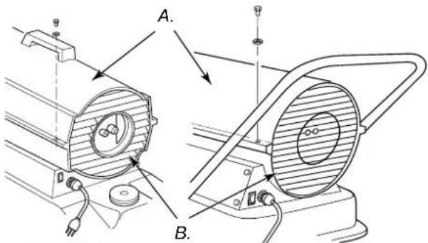
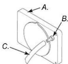
(see figure 7 e 8)
A. Upper shell, B. Fan guard.
Figure 7-8 – Upper Shell Removal.
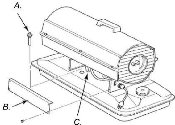
(see figure 9)
A. Fuel Filter, B. Side cover, C. Fuel line.
Figure 9 – Fuel Filter Removal, 35.000 and 70.000 Btu/Hr.
(see figure 10)
A. Fuel Filter, Bushing, and Lower Fuel Line, B. Upper fuel line, C. Side cover.
Figure 10 – Fuel Filter Removal, 100.000 Btu/Hr.
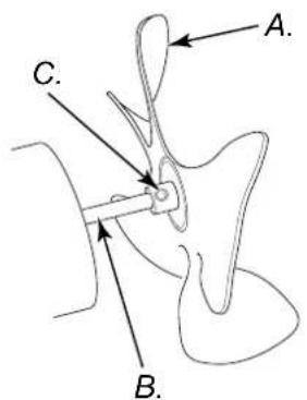
IGNITOR
- Remove upper shell and fan guard (see figure 7-8).
-
Remove fan (see page 11).
-
Remove 4 side cover screws with a 5/16" nut driver. Remove side cover (see Figure 9 or 10).
- Disconnect ignitor wires (yellow) from ignition control assembly (see Figure 11). Pull the ignitor wires up through the hole in the lower shell.
- Disconnect fuel line hose and air linehose. Remove photocell from photocell bracket (see Figure 11).
- Remove combustion chamber. Stand combustion chamber on end with nozzle adapter bracket on top (see Figure 12).
- Remove ignitor screw with a 1/4" nut driver. Carefully remove ignitor from nozzle adapter bracket.
CAUTION: Do not bend or strike ignitor element. Handle with care.
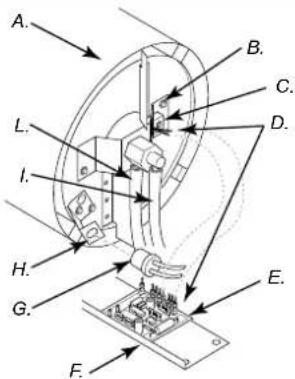
(see figure 11)
A. Combustion Chamber
B. Nozzle Adapter Bracket
C. Ignitor
D. Ignitor Wires
E. Ignition Control
Assembly
F.Side Cover
G. Photocell Assembly
H. Photocell Bracket
1.Fuel Line Hose
L.Air Line Hose
Figure 11 – Disconnecting Ignitor Wire sfrom Ignition Control Assembly.
- Carefully remove replacement ignitor from styrofoam packing.
- Carefully guide ignitor into opening in nozzle adapter bracket. Do not strike ignitor element. Attach ignitor to nozzle adapter bracket with screw using a 1/4" nut driver (see Figure 12). Torque .90 to 1.69 N-m (8 to 15 in-lbs) Do not over torque.
- Replace combustion chamber.
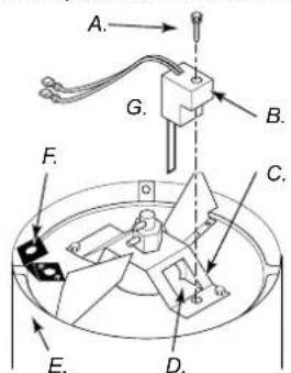
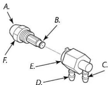
(see figure 12)
A. Ignitor Screw/Washer
Assembly
B.Ignitor
C. Nozzle Adapter Bracket
D. Nozzle Adapter Bracket
Opening
E. Combustion Chamber
F. Photocell Bracket
G.Ignitor Element
Figure 12 – Ignitor Replacement
- Route the ignitor wires back down through the hole in the lower shell. Connect wires to the ignition control assembly.
- Replace side cover (see Figure 9 or 10).
- Connect and route fuel line hose and air line hose to burner head. See Fuel and Air Line Replacement and Proper Routing, page 11.
- Replace photocell in photocell bracket. Route wires as shown in either Figure 17, 18, or 19, page 11.
- Replace fan (see page 13).
- Replace fan guard and upper shell (see figure 7-8).
SERVICE PROCEDURES
Continued
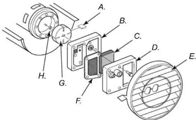
AIR OUTPUT, AIR INTAKE, AND LINT FILTERS
- Remove upper shell (see page 6).
- Remove fi Iter end cover screws using 5/16" nut-driver.
- Remove fi Iter end cover.
- Replace air output and lint filters.
- Wash or replace air intake filter (see Preventative Maintenance Schedule, page 5).
- Replace fi Iter end cover.
- Replace fan guard and upper shell.
IMPORTANT: Do not oil fi Iters.
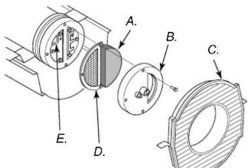
Figure 13 – Air output, air intake and lint filters, 35.000 and 70.000 Btu/Hr.
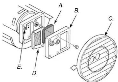
Figure 14 – Air output, air intake and lint fi Iters, 100.000 Btu/Hr.
(see figure 13 e 14)
A. Air Intake Filter, B. Filter end cover, C. fan guard
D. Air output filter, E. Lint Filter.
NOZZLE ASSEMBLY
- Remove upper shell (see page 7).
- Remove fan (see page 11).
- Remove fuel and air line hoses from nozzle assembly (see Figure 17, 18 or 19).
- Turn nozzle assembly 1/4 turn to left and pull toward motor to remove (see Figure 20).
- Place plastic hex-body into vise and lightly tighten.
- Carefully remove nozzle from the nozzle adapter using 5/8" socket wrench (see Figure 21).
- Blow compressed air through face of nozzle. This will free any dirt in nozzle area.
- Inspect nozzle seal for damage.
- Replace nozzle into nozzle adapter until nozzle seats. Tighten 1/3 turn more using 5/8" socket wrench 4.5 to 5.1 N-m (40 to 45 in-lbs). See Figure 21.
- Attach nozzle assembly to burner strap.
- Attach fuel and airline hoses to nozzle assembly. See Fuel and Airline Replacement and Proper Routing see page 9.
- Replace fan (see page 11).
- Replace fan guard and upper shell (see page 7).
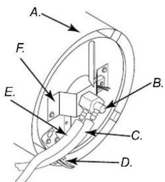
A. Combustion Chamber
B. Nozzle/Adapter Assembly
C. Fuel Line Hose
D. Air Line Hose
E. Photocell Bracket
F. Nozzle Adapter Bracket
Figure 17 – Removing air and fuel line hoses, 35.000 and 70.000 Btu/Hr Models.
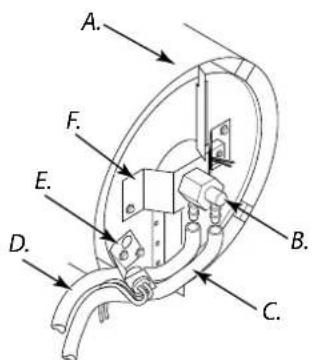
A. Combustion Chamber
B. Nozzle/Adapter Assembly
C. Fuel Line Hose
D. Photocell Bracket
E. Air Line Hose
F. Nozzle Adapter Bracket
Figure 18 – Removing air and fuel line hoses, (100.000 Btu/Hr).
A. Combustion Chamber
B. Nozzle/Adapter Assembly
C. Fuel Line Hose
D. Air Line Hose
E. Photocell Bracket
F. Nozzle Adapter Bracket
Figure 19 – Removing air and fuel line hoses (150.000 Btu/Hr).
A. Combustion Chamber
B. Nozzle/Adapter Assembly
Figure 20 - Removing nozzle/adapter assembly
A. Nozzle face
B. Nozzle seal
C. Fuel line fitting
D. Air line fi tting
E. Nozzle adapter
F. Nozzle
Figure 21 - Nozzle and nozzle adapter.
FUEL AND AIR LINE REPLACEMENT AND PROPER ROUTING
- Remove upper shell (see page 7).
- Remove side cover screws using 5/16" nut driver.
- Remove side cover.
- nspct fuel and air line hoses for cracks and/or holes. If fuel line hose is damaged, disconnect from nozzle adapter (see Figure 17, 18, or 19) and from fuel filter (see page 6). If air line hose is damaged, disconnect from nozzle adapter (see Figure 17, 18, or 19) and from barb fi tting on pump end cover (see Figure 22).
- Install new air and/or fuel line. Attach one end of air line hose to barb fi tting on pump end cover (see Figure 22) and the other end to nozzle adapter (see Figure 17, 18, or 19). Attach one end of fuel line hose to fuel fi liter (see page 6) and the other end to nozzle adapter (see Figure 17, 18, or 19).
For 35.000 and 70.000 Btu/Hr model heaters, route air and fuel lines approximately as shown in Figure 17.
Note: Hoses are not to be touching photocell bracket.
For 100.000 Btu/Hr model heater, route air and fuel lines approximately as shown in Figure 18.
Note: Hoses are not to be touching photocell bracket.
For 150.000 Btu/Hr model heater, route air and fuel lines approximately as shown in Figure 19.
Note: Hoses are not to be touching photocell bracket. - Replace side cover.
- Replace upper shell and fan guard (see page 7).
A. Pump end cover
B. Barb fi tting
C. Air hose
Figure 22 – Air hose to barb fl itting
Continued
SERVICE PROCEDURES
Continued
PUMP ROTOR
(Procedure if Rotor is Binding)
- Remove upper shell (see page 7).
- Remove fi Iter end cover screws using5/16" nut-driver.
- Remove filter end cover and air filters.
- Remove pump plate screws using 5/16"nut-driver.
- Remove pump plate.
- Remove rotor, insert, and blades.
- Check for debris in pump. If debris is found, blow out with compressed air.
- Install insert and rotor.
- Check gap on rotor. Adjust to .076/.101 mm (.003"/.004") if needed (see Figure 25).
Note: Rotate rotor one full turn to ensure the gap is .076/.101 mm (.003"/.004") at tightest position. Adjust if needed.
- Install blades, pump plate, air filters and filter end cover.
- Replace fan guard and upper shell.
- Adjust pump pressure (see page 8).
Note: If rotor is still binding, proceed as follows.
- Perform steps 1 through 6 above.
- Place fine grade sandpaper (600 grit) on flat surface. Sand rotor lightly in "fi gure 8" motion four times (see Figure 26)
- Reinstall insert and rotor.
- Perform steps 10 through 12 above.
A.Blade, B.Pump plate, C.Air intake filter, D.Filter end cover, E.Fan guard, F.Air output filter, G.Rotor, H.Insert. Figure 24 – Rotor location, 100.000 Btu/Hr.
A. gap adjusting screw
B. .076/.101 mm (.003"/.004") Gap
Measured With
Feeler Gauge
C. Blade
Figure 25 - Gap adjusting screw locations.
A.Blade, B.Pump plate, C.Air intake filter, D.Filter end cover, E.Fan guard, F.Air output filter, G.Rotor, H.Insert.
Figure 23 – Rotor location, 35.000 btu/Hr and 70.000 Btu/Hr.
Figure 26 – Sanding rotor.
FAN
IMPORTANT: Remove fan from motor shaft before removing motor from heater. The weight of the motor resting on the fan could damage the fan pitch.
- Remove upper shell (see page 7).
- Use 1/8" allen wrench to loosen setscrew which holds fan to motor shaft.
- Slip fan off motor shaft.
- Clean fan using a soft cloth moistened with kerosene or solvent.
- Dry fan thoroughly.
- Replace fan on motor shaft. Place fan hub flush with end of motor shaft (see Figure 28).
- Place setscrew on flat of shaft. Tighten setscrew firmly 4.5 to 5.6 N-m (40 to 50 in-lbs).
- Replace fan guard and upper shell.
A.Fan, B.Motor shaft, C.Set screw, D.Flush.
Figure 27 – Fan, motor shaft Figure 28 – Fan cross and setscrew location. section.
IGNITION CONTROL ASSEMBLY

WARNING: Unplug heater before servicing.
Remove Old Assembly
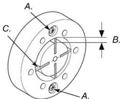
- Using the 5/16" nut driver or socket wrench, remove the four side cover screws (see Figure 29).
- Disconnect the nine wires from the ignition control assembly.
- Using needle nose pliers, squeeze the tab on the printed circuit board support and lift up on the edge of the ignition control assembly (see Figure 30). Repeat this for the other four printed circuit board supports then remove the assembly.
A. Side cover
natural_image
Technical line drawing of a mechanical device with labeled component A, showing internal components and alignment lines (no text or symbols beyond label)Figure 29 – removing cover.
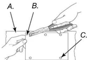
Figure 30 - Removing circuit board
A. Side cover
B. Ignition Contro | Assembly
C. Printed Circuit
Board Supports (5)
Installing the New Assembly

CAUTION: Ignition control assembly contains poststatic components. Handle the assembly by the use of the printed circuit board. Do not touch any of quick connect terminals or electronic components.
- Align the five holes in the assembly with the five printed circuit board supports in the side cover.
- Holding the assembly by the edges of the printed circuit board, apply downward pressure until all fi ve tabs on the printed circuit board supports springlock into place. Pull up on assembly to verify this (see Figure 31).
- Connect the nine wire leads to the ignition control assembly as shown in the wiring diagram on page 17.

CAUTION: Double check connections. Connecting ion control assembly wrong could result in damage to ignition control assembly and/or other components to heater assembly.
- Using the 5/16" nut driver or socket wrench reinstall side cover to heater. Tighten screws until snug. Do not over torque!
A. Unacceptable
B. Acceptable
Figure 31 - Attaching Circuit Board to Tabs.
ILLUSTRATED PARTS BREAKDOWN
35.000 and 70.000 Btu/Hr
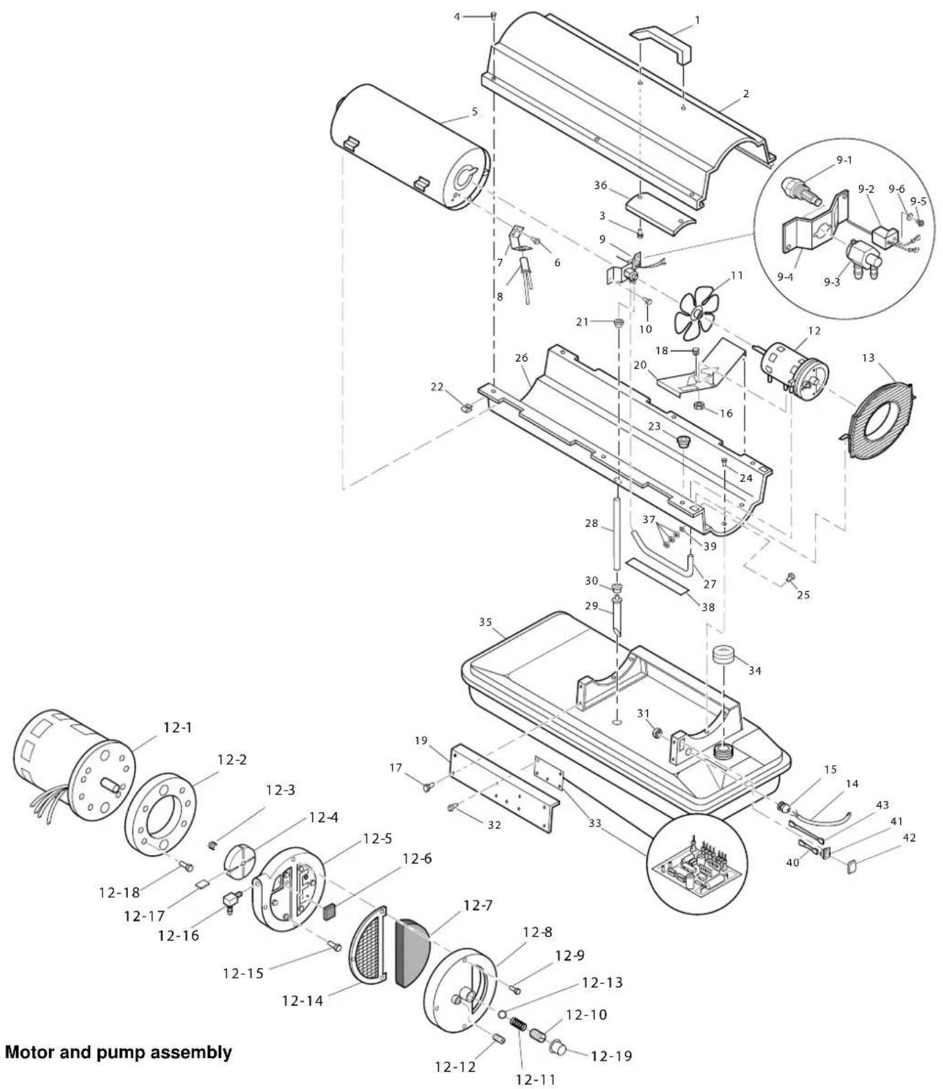
PARTS LIST
35.000 and 70.000 Btu/Hr
This list contains replaceable parts used in your heater. When ordering parts, be sure to provide the correct model and serial numbers (from the model plate), then the part number and description of the desired part.
| Ersatzteil - No Ersatzteil | - No | ||||||
| Art.-No Ver.-No Pos.-No | DESCRIPTION | Art.-No Ver.-No Pos.-No | DESCRIPTION | ||||
| 85090/85091 | 01 | 001 | Handle | 85090/85091 | 01 | 12-17 | Blade (10 kW) |
| 85090/85091 | 01 | 002 | Upper Shell | 85090/85091 | 01 | 12-18 | Blade (20 kW) |
| 85090/85091 | 01 | 003 | Screw | 85090/85091 | 01 | 12-18 | Screw (10 kW) |
| 85090/85091 | 01 | 004 | Screw/Lockwasher | 85090/85091 | 01 | 12-18 | Screw (20 kW) |
| 85090/85091 | 01 | 005 | Combustion Chamber | 85090/85091 | 01 | 12-19 | Plastic Cap |
| 85090/85091 | 01 | 006 | Screw | 85090/85091 | 01 | 013 | Fan Guard |
| 85090/85091 | 01 | 007 | Photocell Bracket | 85090/85091 | 01 | 014 | Power Cord |
| 85090/85091 | 01 | 008 | Photocell Assembly | 85090/85091 | 01 | 015 | Strain Relief Bushing |
| 85090/85091 | 01 | 009 | Burner Strap Assembly | 85090/85091 | 01 | 016 | Hex Lock Nut, 1/4-20 |
| 85090/85091 | 01 | 09-1 | Nozzle Assembly (10 kW) | 85090/85091 | 01 | 017 | Screw/Lockwasher, 1/2" |
| 85090/85091 | 01 | 09-1 | Nozzle Assembly (20 kW) | 85090/85091 | 01 | 018 | Rubber Bumper |
| 85090/85091 | 01 | 09-2 | Ignitor Kit | 85090/85091 | 01 | 019 | Side Cover |
| 85090/85091 | 01 | 09-3 | Nozzle Adapter | 85090/85091 | 01 | 020 | Motor Bracket |
| 85090/85091 | 01 | 09-4 | Nozzle Adapter Bracket | 85090/85091 | 01 | 021 | Bushing |
| 85090/85091 | 01 | 09-5 | Screw | 85090/85091 | 01 | 022 | Clip Nut |
| 85090/85091 | 01 | 09-6 | Belleville Washer | 85090/85091 | 01 | 023 | Bushing |
| 85090/85091 | 01 | 010 | Screw/Lockwasher | 85090/85091 | 01 | 024 | Screw/Lockwasher, 1/2" |
| 85090/85091 | 01 | 011 | Fan | 85090/85091 | 01 | 025 | Screw |
| 85090/85091 | 01 | 012 | Motor and Pump Assembly | 85090/85091 | 01 | 026 | Lower Shell |
| 85090/85091 | 01 | 12-1 | Motor (10 kW) | 85090/85091 | 01 | 027 | Rubber Airline |
| 85090/85091 | 01 | 12-1 | Motor (20 kW) | 85090/85091 | 01 | 028 | Fuel Line |
| 85090/85091 | 01 | 12-2 | Pump Body (10 kW) | 85090/85091 | 01 | 029 | Fuel Filter (10 kW) |
| 85090/85091 | 01 | 12-2 | Pump Body (20 kW) | 85090/85091 | 01 | 029 | Fuel Filter (20 kW) |
| 85090/85091 | 01 | 12-3 | Insert | 85090/85091 | 01 | 030 | Rubber Bushing |
| 85090/85091 | 01 | 12-4 | Rotor (10 kW) | 85090/85091 | 01 | 031 | Nylon Locknut |
| 85090/85091 | 01 | 12-4 | Rotor (20 kW) | 85090/85091 | 01 | 032 | PCB Support |
| 85090/85091 | 01 | 12-5 | Pump End Cover | 85090/85091 | 01 | 033 | Ignition Control Assembly |
| 85090/85091 | 01 | 12-6 | Lint Filter | 85090/85091 | 01 | 034 | Fuel Cap (Includes Gasket) |
| 85090/85091 | 01 | 12-7 | Intake Filter | 85090/85091 | 01 | 035 | Fuel Tank (10 kW) |
| 85090/85091 | 01 | 12-8 | Filter End Cover | 85090/85091 | 01 | 035 | Fuel Tank (20 kW) |
| 85090/85091 | 01 | 12-9 | Screw | 85090/85091 | 01 | 036 | Shell Heat-Shield |
| 85090/85091 | 01 | 12-10 | Adjusting Screw | 85090/85091 | 01 | 037 | Nut |
| 85090/85091 | 01 | 12-11 | Pressure Relief Spring | 85090/85091 | 01 | 038 | Vinyl Foam Gasket |
| 85090/85091 | 01 | 12-12 | Plug | 85090/85091 | 01 | 039 | Lockwasher |
| 85090/85091 | 01 | 12-13 | Steel Ball, 1/4" Diameter | 85090/85091 | 01 | 040 | Wire Assembly (Brown) |
| 85090/85091 | 01 | 12-14 | Output Filter | 85090/85091 | 01 | 041 | ON/OFF Switch |
| 85090/85091 | 01 | 12-15 | Screw (10 kW) | 85090/85091 | 01 | 042 | Switch Cover |
| 85090/85091 | 01 | 12-15 | Screw (20 kW) | 85090/85091 | 01 | 043 | Wire Assembly (White) |
| 85090/85091 | 01 | 12-16 | Nylon Elbow, 90° | ||||
(10 kW)=35.000 Btu/h
(20 kW)=70.000 Btu/h
ILLUSTRATED PARTS BREAKDOWN
100.000 Btu/Hr
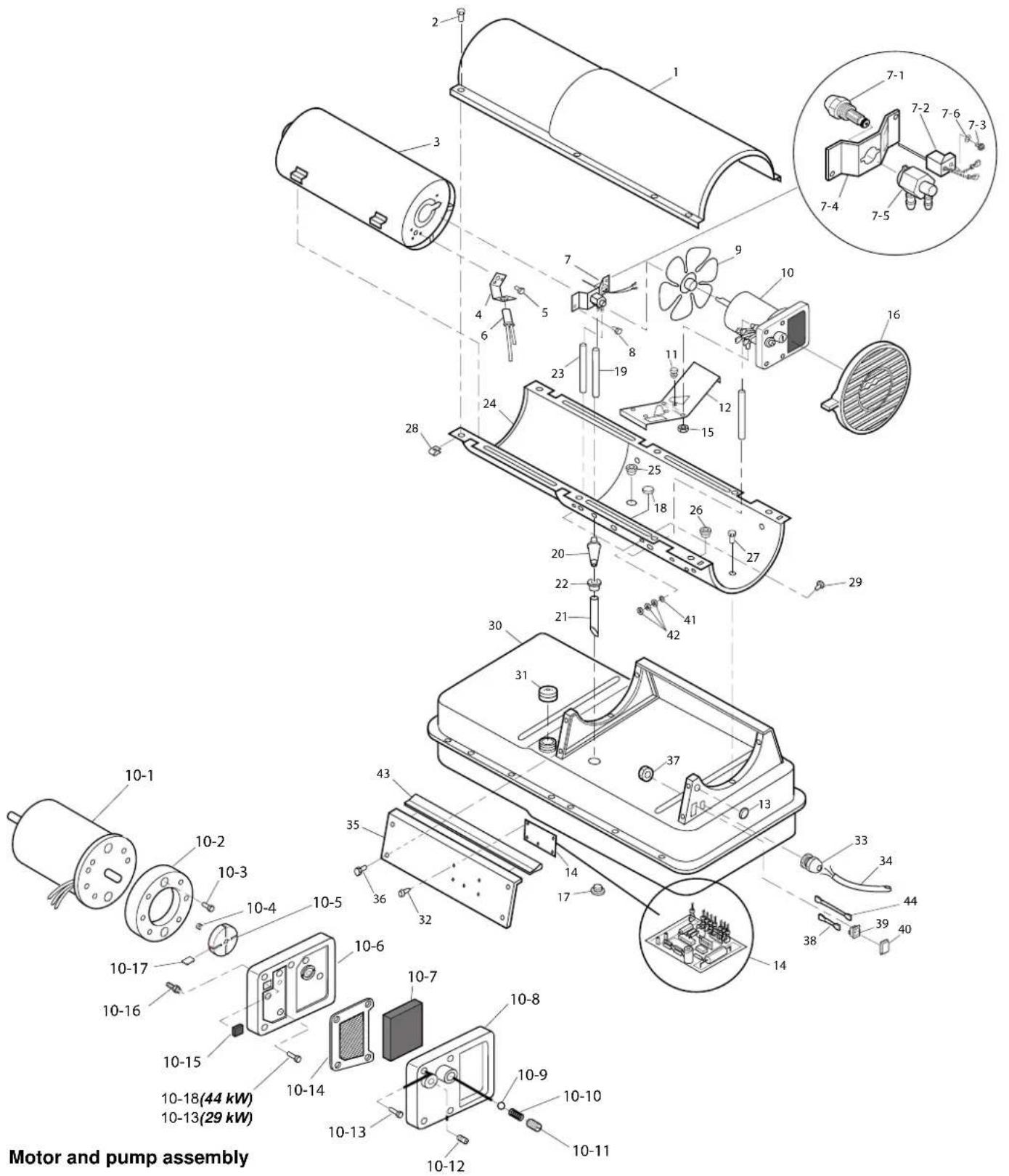
PARTS LIST
100.000 Btu/Hr
This list contains replaceable parts used in your heater. When ordering parts, be sure to provide the correct model and serial numbers (from the model plate), then the part number and description of the desired part.
| Ersatzteil - No Ersatzteil | - No | ||||||
| Art.-No Ver. | -No Pos.- | No DESCR | IPTION Art.-No Ver.-No Pos.-No | DESCRIPTION | |||
| 85092 | 01 | 001 | Upper Shell | 85092 | 01 | 012 | Motor Mounting Bracket |
| 85092 | 01 | 002 | Screw/Lockwasher, 1/2" | 85092 | 01 | 013 | Button Plug |
| 85092 | 01 | 003 | Combustion Chamber | 85092 | 01 | 014 | Igniton Control Assembly |
| 85092 | 01 | 004 | Photocell Bracket | 85092 | 01 | 015 | Hex Lock Nut, 1/4-20 |
| 85092 | 01 | 005 | Screw | 85092 | 01 | 016 | Fan Guard |
| 85092 | 01 | 006 | Photocell Assembly | 85092 | 01 | 017 | Drain Plug (Includes "o" Ring) |
| 85092 | 01 | 007 | Burner Strap Assembly | ||||
| 85092 | 01 | 07-1 | Nozzle Assembly | 85092 | 01 | 018 | Button Plug |
| 85092 | 01 | 07-2 | Ignitor Kit | 85092 | 01 | 019 | Fuel Line |
| 85092 | 01 | 07-3 | Screw | 85092 | 01 | 020 | Fuel Filter |
| 85092 | 01 | 07-4 | Nozzle Adapter Bracket | 85092 | 01 | 021 | Fuel Line Tube |
| 85092 | 01 | 07-5 | Nozzle Adapter | 85092 | 01 | 022 | Rubber Bushing |
| 85092 | 01 | 07-6 | Belleville Washer | 85092 | 01 | 023 | Airline |
| 85092 | 01 | 008 | Screw/Lockwasher, 1/2" | 85092 | 01 | 024 | Lower Shell |
| 85092 | 01 | 009 | Fan | 85092 | 01 | 025 | Bushing |
| 85092 | 01 | 010 | Motor and Pump Assembly | 85092 | 01 | 026 | Bushing |
| 85092 | 01 | 010-1 | Motor | 85092 | 01 | 027 | Screw/Lockwasher, 1/2" |
| 85092 | 01 | 010-2 | Pump Body | 85092 | 01 | 028 | Clip Nut |
| 85092 | 01 | 010-3 | Screw | 85092 | 01 | 029 | Screw |
| 85092 | 01 | 010-4 | Rotor Insert | 85092 | 01 | 030 | Fuel Tank |
| 85092 | 01 | 010-5 | Pump Rotor | 85092 | 01 | 031 | Fuel Cap (Includes Gasket) |
| 85092 | 01 | 012-6 | Pump End Cover | 85092 | 01 | 032 | P.C. Board Support |
| 85092 | 01 | 010-7 | Intake Filter | 85092 | 01 | 033 | Strain Relief Bushing |
| 85092 | 01 | 010-8 | Filter End Cover | 85092 | 01 | 034 | Power Cord |
| 85092 | 01 | 010-9 | Steel Ball, 1/4" Diameter | 85092 | 01 | 035 | Side Cover |
| 85092 | 01 | 10-10 | Relief Spring | 85092 | 01 | 036 | Screw/Lockwasher, 1/2" |
| 85092 | 01 | 10-11 | Adjusting Screw | 85092 | 01 | 037 | Nylon Locknut |
| 85092 | 01 | 10-12 | Plug | 85092 | 01 | 038 | Wire Assembly (Brown) |
| 85092 | 01 | 10-13 | Screw | 85092 | 01 | 039 | ON/OFF Switch |
| 85092 | 01 | 10-14 | Output Filter | 85092 | 01 | 040 | Switch Cover |
| 85092 | 01 | 10-15 | Lint Filter | 85092 | 01 | 041 | Lockwasher, #10 |
| 85092 | 01 | 10-16 | Barb Fitting | 85092 | 01 | 042 | Nut |
| 85092 | 01 | 10-17 | Blade | 85092 | 01 | 043 | Edge Liner |
| 85092 | 01 | 011 | Rubber Bumper | 85092 | 01 | 044 | Wire Assembly (White) |
WHEELS ANDHANDLES
100.000 Btu/Hr models
| KEY NO. | PART MUNBER | PART DESCRIPTION Q.TY. | |
| 1 | 4110.077 | Handles | 1 |
| 2 | 4110.144 | Screw | 8 |
| 3 | 4110.078 | Wheel Support Frame | 1 |
| 4 | 4110.143 | Hex Nut | 8 |
| 5 | 4110.084 | Wheel (2) | 2 |
| 6 | 4110.085 | Cap Nut | 2 |
| 7 | 4110.109 | Axle | 1 |
SPECIFICATIONS
| Output Rating (kw/Btu/h) | 10 | 20 | 29 |
| 35.000 | 70.000 | 100.000 | |
| Fuel | Use Only Kerosene or No. 1 Fuel Oil | ||
| Fuel Tank Capacity (U.S. Gal.) | 4 | 5 | 11,5 |
| Fuel Consumption (Gal x Hr) | 0,28 | 0,52 | 0,79 |
| Electric Requirements | 220-240 V /50 Hz | ||
| Amperage | 0,8 | 1 | 1,2 |
| Hot Air Output (m3/h) | 280 | 400 | 800 |
| RPM | 1425 | 2850 | 2850 |
WIRING DIAGRAM
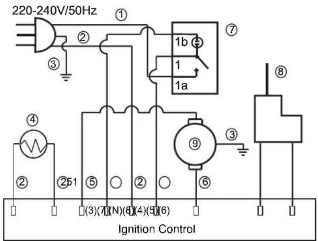
① Brown
② Blue
③ Green-yellow
④ Photocell
⑤ White
⑥ Red
⑦ ON/OFFSwitch
⑧ Ignitor
⑨ Motor
That the following Appliance complies with the appropriate basic safety and health requirements of the EC Directive based on its design and type, as brought into circulation by us.
In a case of modification of the machine, not agreed upon by us, this declaration will lose its validity.
natural_image
Four industrial lighting machines labeled GD 10 E, GD 30 IE, GD 20 IE, and a plain background (no text or symbols on the devices themselves)# 85090, 85091, 85092
CE
Güde GmbH & Co. KG
Birkichstraße 6
D-74549 Wolpertshausen
Güde Scandinavia A/S
Engelsholmvej 33
DK-8900 Randers
Guede Czech s.r.o.
P.O. Box 8
Poèernická 120
CZ-360 05 Karlovy Vary
GÜDE Slovakia s.r.o
Podtúreò-Roveò 208
SK-033 01 Liptovský
Hrádok
www.guede.com
www.guede.com
www.unicore.cz
www.guede.com
NOTES SUR LA SÉCURITÉ

AVERTISSEMENTS
(voir figure 1, e 2)
(voir fi g. 11)
(voir fi g. 12)
A. Ensemble vis/rondelle
B. Allumeur
REEMPLACEMENT ET ACHEMINEMENT CORRECT DES CONDUITES DE COMBUSTIBLE ET D'AIR
natural_image
Technical line drawing of a mechanical device with no visible text or symbolsSPÉCIFICATIONS
We herewith declare,
Güde GmbH & Co. KG
Birkichstraße 6, 74549 Wolpertshausen, Germany
That the following Appliance complies with the appropriate basic safety and health requirements of the EC Directive based on its design and type, as brought into circulation by us.
In case of modification of the machine, not agreed upon by us, this declaration will lose its validity.
Machine Description:
Applicable EC Directives:
Applicable harmonized Standards:
Lien/Place:
Position within the company:
Wolpertshausen
18.03.2008,


- SPECIFICATIONS - SPÉCIFICATIONS - TECHNISCHE DATEN - TECHNISCHE GEGEVENS - DATI TECNICI - ASPECIFICACIONES - SPECIFIKATIONER - TEKNISET TIEDOT - SPECIFIKATIONER - SPESIFIKASJONER - SPECYFIKACJE - TEXНИЧЕСКИЕ
- SICHERHEITS
- INFORMATIONEN
- WARNHINWEISE
- SAFETY INFORMATION
- ⚠️ WARNINGS
- PRODUCT IDENTIFICATION
- UNPACKING
- FUELS
- ASSEMBLY
- (for 100.000 Btu/Hr models only)
- Tools Needed
- VENTILATION
- THEORY OF OPERATION
- OPERATION
- TO START HEATER
- Extension cord wire size requirements:
- TO STOP HEATER
- TO RESET HEATER
- STORING, TRANSPORTING, OR SHIPPING
- PREVENTATIVE MAINTENANCE SCHEDULE
- TROUBLESHOOTING
- HEATER WITH FUSED OR NON-FUSED IGNITION CONTROL ASSEMBLY
- Continued
- SERVICE PROCEDURES
- UPPER SHELL REMOVAL
- FUEL FILTER
- (35.000 and 70.000 Btu/Hr Models)
- (100.000 Btu/Hr Models)
- IGNITOR
- Figure 12 – Ignitor Replacement
- AIR OUTPUT, AIR INTAKE, AND LINT FILTERS
- NOZZLE ASSEMBLY
- FUEL AND AIR LINE REPLACEMENT AND PROPER ROUTING
- PUMP ROTOR
- (Procedure if Rotor is Binding)
- FAN
- IGNITION CONTROL ASSEMBLY
- WARNING: Unplug heater before servicing.
- Remove Old Assembly
- Installing the New Assembly
- ILLUSTRATED PARTS BREAKDOWN
- PARTS LIST
- and 70.000 Btu/Hr
- WHEELS ANDHANDLES
- NOTES SUR LA SÉCURITÉ
- AVERTISSEMENTS
- REEMPLACEMENT ET ACHEMINEMENT CORRECT DES CONDUITES DE COMBUSTIBLE ET D'AIR
Brand : Güde
Model : GD 10 E
Category : Heating