
iMow 5.0 EVO - Lawn mower STIHL - Free user manual and instructions
Find the device manual for free iMow 5.0 EVO STIHL in PDF.


User questions about iMow 5.0 EVO STIHL
0 question about this device. Answer the ones you know or ask your own.
Ask a new question about this device
Download the instructions for your Lawn mower in PDF format for free! Find your manual iMow 5.0 EVO - STIHL and take your electronic device back in hand. On this page are published all the documents necessary for the use of your device. iMow 5.0 EVO by STIHL.
USER MANUAL iMow 5.0 EVO STIHL
natural_image
Black and white photo of a modern robotic car with visible wheels and safety warning symbols (no text or labels)text_image
Labeled diagram of a device with numbered components and a magnified inset showing internal structure.1 Netzstecker
natural_image
Technical illustration of a mechanical device with pins and a separate diagram showing four pins labeled '12' (no text or symbols on the devices themselves)12 Erdnagel
text_image
1 IMOW 0000098832_0011 iMOW® Ruler
text_image
1 2 3 STINHL 4 0000098833_0011 Fixiernagel
text_image
6 7 8 0000100413_001text_image
Illustration showing various objects including a soccer ball, a cross, water droplet, and a bucket with a labeled dimension 'a'natural_image
Line drawing of a robotic lawn mower on a paved path beside tall grass and trees (no text or symbols)text_image
0000098825_001 atext_image
0000098842_001 1 Wi-Fitext_image
Diagram illustrating four different types of metal cutting tools: a saw, a tool with crosshair, a tool with flat blade, and a tool with flat blade.text_image
90° 1 a 000009845_001text_image
Technical diagram illustrating a mechanical or fluid system with labeled components and directional arrows, including annotations 'a', 'b', and 'c'.text_image
Diagram showing a device with cable and connector, including a magnified inset highlighting internal components with arrows.natural_image
Illustration of a manual push-button press device with a magnified inset showing the handle (no text or symbols present)text_image
1 000098854_001text_image
Technical diagram of a mechanical assembly with numbered components and directional arrows indicating motion or forcenatural_image
Technical diagram of a mechanical assembly with arrows indicating motion or force direction (no text or symbols present)natural_image
Technical illustration of a mechanical device with pins and a numbered component (no text or symbols present)text_image
Technical diagram showing mechanical assembly with labeled parts and a magnified inset highlighting a component detail.text_image
Technical diagram showing a vehicle's seatbelt mechanism with labeled parts 1, 3, and 4, including a magnified inset view.text_image
Diagram showing a mechanical device with labeled parts and a wire spool, likely illustrating a cable or cable connection.text_image
Diagram of a mechanical device with labeled parts and connection, including a spool and lever mechanismtext_image
Diagram of a mechanical device with labeled parts and wiring, showing connections between a spring and a spool.text_image
Diagram showing cable connection with labeled parts and magnified detail viewtext_image
Technical diagram showing a mechanical assembly with numbered components and an inset close-up of a device labeled '4'text_image
Technical diagram showing mechanical assembly with labeled parts and a magnified inset highlighting a component detail.text_image
Technical diagram showing a vehicle's seatbelt mechanism with labeled parts 1, 3, and 4, including a magnified inset view.text_image
Technical diagram showing a mechanical assembly with labeled components and directional arrows, including parts labeled 1 and 3.text_image
1 a b 2 c 000009843_001text_image
a 0000100053_001text_image
0000100058_001 atext_image
Diagram showing a vehicle with a road, a brain icon, a skull, and a cross symbol, possibly representing a road or navigation system.text_image
Diagram illustrating a mechanical setup with labeled components and a magnified view of a cutting tool tip.natural_image
Line drawing of a robotic car on a paved surface next to a wall with brick barriers (no text or symbols)text_image
a 0000100082_001text_image
a 0000100063_001text_image
a a 1 b 0000100055_001text_image
Diagram illustrating a mechanical or structural assembly with directional arrows and labeled points, likely from an engineering or physics context.text_image
1 b a 1 b 00000100085_001text_image
1 4 3 4 5 000010/1523_001natural_image
Line drawing of a car on a path with trees and an arrow indicating direction (no text or symbols)text_image
a b c 000010088_001text_image
Technical diagram showing a mechanical assembly with labeled parts including a brush, wire spool, and tool holder.text_image
5 1 000010245_001text_image
STINL 1 6 0000100246_001text_image
Diagram showing mechanical components and a magnified view of a component labeled '1' and '2', with a watermark at the bottom.text_image
Diagram illustrating a mechanical or electrical procedure with labeled components including a tool, switch, and wire spool.text_image
Technical diagram showing a mechanical assembly with labeled components and a close-up of a tool interacting with a device labeled 1, 2, and 3.text_image
Technical diagram illustrating a sewing or drafting procedure with labeled components and a magnified view of the tool's working principle.text_image
STINL 1 6 0000100246_001text_image
Technical diagram of a mechanical assembly with labeled parts and directional arrows, including a magnified inset showing component 2.text_image
Technical diagram showing mechanical assembly with labeled parts and a spool, likely illustrating a cable or fiber connection.text_image
Technical diagram showing a mechanical assembly with numbered components and a spool, likely illustrating a gear or component assembly.text_image
Technical diagram showing mechanical assembly steps with numbered components and checkmark indicatorstext_image
1 8 8 0000100231_001text_image
Technical diagram showing a tool being adjusted into a mechanical component with labeled parts 1 and 2.text_image
Technical diagram showing a tool in a mechanical assembly with labeled parts and a checkmark indicating inspection or confirmation.text_image
R 1 L 3 0000*00250_001natural_image
Mechanical component diagram showing a highlighted part labeled '4' (no text or symbols beyond label)text_image
1 2 3 0000089971_001text_image
STIL 0000100254_001natural_image
Line drawing of a person using a device to adjust or install a device (no text or symbols visible)text_image
Diagram of a vacuum cleaner with labeled parts and a magnified inset showing internal componentstext_image
Diagram showing a device with labeled parts and an inset magnified view of its internal components.natural_image
Mechanical device with a highlighted component and arrow indicator (no text or symbols)text_image
Diagram illustrating a device with arrows indicating process, including an inset showing hand positioning and a page number.text_image
1 2 3 4 10_0_0101010000natural_image
Technical line drawing of a mechanical assembly with hands and components, no visible text or symbolsnatural_image
Technical line drawing of a mechanical component with concentric rings and a labeled inset (no text or symbols)natural_image
Technical line drawing of a robotic lawn mower with labeled component (no text or symbols present)text_image
Technical diagram of a robotic car with labeled parts 1 and 2, showing internal components and motion indicators.text_image
7 7 7 0000-100284_001natural_image
Technical diagram of a mechanical component with numbered parts (no text or symbols)text_image
a 0000100242_001text_image
Technical diagram showing mechanical assembly steps with labeled components and checkmark indicators– LTE-Cat-M1: B1, B2, B3, B4, B5, B8, B12, B13, B20, B28, B66
- UMTS, HSDPA, HSPA+: B1, B2, B4, B5, B6, B8, B19
– GSM, GPRS, EDGE: 850 MHz, 900 MHz, 1800 MHz, 1900 MHz
Robert Olma, Vice President, Regulatory Affairs & Global Governmental Relations
27 Open Source Software
27.1 Open Source Software
6 Preparing the Mowing Area and Robot Mower for Operation.... 61
7 Positioning the docking station.... 62
8 Installing the Perimeter Wire....68
9 Completing the Perimeter Wire Installation 75
10 Installing Guide Wire....78
11 Electrically connecting the docking station 79
12 Charging the Robot Mower.... 81
13 Closing Bluetooth® Radio Interface......81
14 Light patterns on the robot mower and charging station....82
15 Operating and Adjusting the Robot Mower 82
16 Stopping the robot mower and activating the device lock.... 83
17 Transporting....83
18 Storing....84
19 Cleaning....85
20 Maintenance.... 86
21 Repairing....87
22 Troubleshooting.... 88
23 Specifications....88
24 Spare Parts and Accessories....90
25 Disposal....90
26 EC Declaration of Conformity.... 90
27 UKCA Declaration of Conformity.... 91
28 Open Source Software....92
1 Introduction
Dear Customer,
Thank you for choosing STIHL. We develop and manufacture our quality products to meet our customers' requirements. The products are designed for reliability even under extreme conditions.
STIHL also stands for premium service quality. Our dealers guarantee competent advice and instruction as well as comprehensive service support.
STIHL expressly commit themselves to a sustainable and responsible handling of natural resources. This user manual is intended to help you use your STIHL product safely and in an environmentally friendly manner over a long service life.
We thank you for your confidence in us and hope you will enjoy working with your STIHL product.
Dr. Nikolas Stihl
IMPORTANT! READ BEFORE USING AND KEEP IN A SAFE PLACE FOR REFERENCE.
2 Guide to Using this Manual
2.1 Applicable documents
The local safety regulations apply.
▶ In addition to this User Manual, you should also read, understand and retain the following documents:
- Safety information for STIHL batteries and products with built-in battery: www.stihl.com/safety-data-sheets
Additional information on STIHL robotic mowers, compatible accessories and FAQs can be found at support.stihl.com, info.myimow.stihl.com or is available at a STIHL authorized dealer.
The Bluetooth® mark designation and Bluetooth® logos are registered trademarks owned by Bluetooth SIG, Inc. These word marks and logos are used by STIHL under license.
The robotic mower is equipped with a Bluetooth ^® radio interface, a radio network interface and a cellular interface. Local operating restrictions (in aircraft or hospitals, for example) must be observed.
3 Overview English
2.2 Warning Notices in Text

DANGER
■ This notice refers to risks which result in serious or fatal injury.
- Serious or fatal injuries can be avoided by taking the precautions mentioned.

WARNING
■ This notice refers to risks which can result in serious or fatal injury.
- Serious or fatal injuries can be avoided by taking the precautions mentioned.
NOTICE
■ This notice refers to risks which can result in damage to property.
▶ Damage to property can be avoided by taking the precautions mentioned.
2.3 Symbols in Text

This symbol refers to a chapter in this instruction manual.
3 Overview
3.1 Robot mower
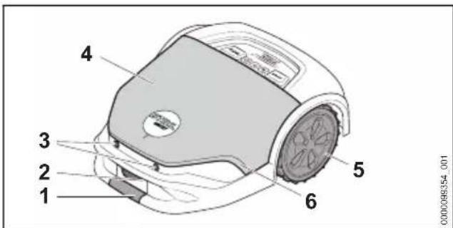
text_image
0000098354_0011 Front grip surface
Lift and transport the robot mower by simultaneously gripping it at the front and rear grip surface.
2 Charging contacts
The charging contacts connect the robot mower with the docking station.
3 Ultrasound sensors
The ultrasound sensors detect obstacles.
4 Hood
The hood is spring-mounted and features a bump sensor to detect obstacles on the mowing area.
5 Drive wheels
The drive wheels drive the robot mower.
6 Light strip
The light strip shows the robot mower's status.
text_image
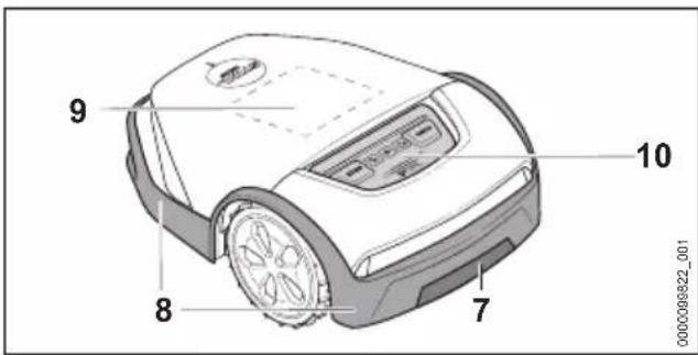
9 8 7 10 000000822_0017 Rear grip surface
Lift and transport the robot mower by simultaneously gripping it at the front and rear grip surface.
8 Protective strip
The protective strip protects the user against ejected objects and contact with the blades.
9 Matrix display
The matrix display shows the robot mower's status.
10 Control panel
The control panel features pushbuttons and a rain sensor.
3.2 Control panel
text_image
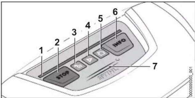
1 2 3 4 5 6 7 STOP INFO SPF/HL1 Light strip
The light strip shows the robot mower's status and signals which key combination to press for a certain action.
2 STOP pushbutton
The pushbutton stops the robot mower and mowing unit. The pushbutton also activates the device lock.
3 LOCK pushbutton
This pushbutton unlocks the robot mower in conjunction with a displayed key combination.
4 START pushbutton
This pushbutton starts mowing operations.
English 3 Overview
5 HOME pushbutton
This pushbutton makes the robot mower return to the docking station or cancels the current mowing job if the robot mower is in the docking station.
6 INFO pushbutton
This pushbutton starts voice output about the current status of the robot mower.
7 Rain sensor
The rain sensor reacts to moisture. Depending on the setting, the robot mower can take weather conditions into account for the mowing plan.
3.3 Mowing unit
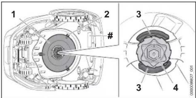
text_image
1 2 # 3 4 0000089827_0011 Blade disk
The blade disk serves to attach the blades.
2 Blades
The blades mow the lawn.
3 Levers
The levers secure the nut.
4 Nut
The nut secures the blade disk.
# Rating plate with the machine number
3.4 Docking station and power supply
text_image
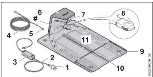
Labeled diagram of a device with numbered components and a magnified inset showing internal wiring or connections.1 Mains plug
The mains plug connects the connecting cable to a socket.
2 Connecting cable
The connecting cable connects the power supply to the mains plug.
50 0458-012-9601-A
3 Power supply
The power supply supplies the docking station with energy.
4 Charging cable
The charging cable connects the power supply to the docking station.
5 Plug
The plug connects the charging cable to the docking station.
6 Hood
The hood covers the docking station and protects the internal electronics.
7 LED
The LED indicates the status of the docking station.
8 Charging contacts
The charging contacts connect the docking station with the robot mower.
9 Base plate
The base plate is the base for the docking station.
10 Cable duct
The guide wire is routed in the middle cable duct.
11 Cable duct
The perimeter wire is routed in the outer cable ducts.
# Rating plate with the machine number
natural_image
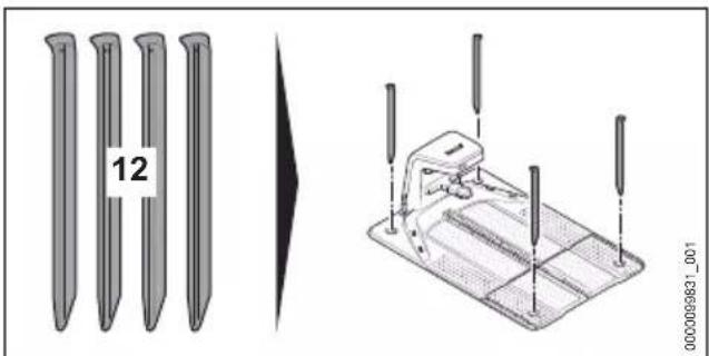
Technical illustration of a mechanical device with pins and a separate view of a pin assembly (no text or symbols)12 Ground peg
The four ground pegs secure the docking station to the ground.
4 Safety Precautions English
3.5 iMOW® Ruler and Installation Kit
iMOW® Ruler
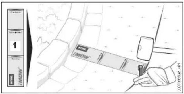
text_image
1 STEL IMOW 000098832_0011 iMOW® Ruler
The ruler makes it easier to install wires and serves to maintain the correct distance.
Installation Kit
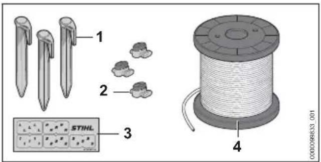
An installation kit is required to commission the robot mower; it is not included in the scope of delivery of the robot mower. Appropriate installation kits are available as accessories for different garden sizes.
text_image
1 2 3 STIHL 4 000098833_0011 Fixing pin
The fixing pin secures the perimeter wire and guide wire to the ground.
2 Wire connector
The wire connector connects wire ends to each other.
3 Cable markers
The cable markers serve to mark wire ends on the inside of the docking station. They facilitate the assignment of the wire ends when connecting to the correct terminal.
4 Wire coil
The wire coil is required to install the perimeter wire and guide wire.
3.6 Symbols
Meanings of symbols on the robot mower, docking station, power supply or installed battery:

This symbol shows the diameter of the blade disk.

This symbol indicates the direction for unlocking the blade carrier when changing blades.

This symbol indicates the direction for locking the blade carrier when changing blades.

Protection class 2, double insulated.

Do not dispose of the product with domestic waste.

The information next to this symbol indicates the energy content of the battery according to the cell manufacturer's specification. The energy content available during use is lower.
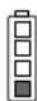

1 LED lights up red. The battery is too warm or too cold.


4 LEDs flash red. There is a fault in the battery.
4 Safety Precautions
4.1 Warning symbols
Meanings of warning symbols on the robot mower, docking station, power supply or installed battery:

Observe safety instructions and take the necessary precautions.

Read and understand the User Manual and keep it in a safe place.

[Non-Text]

Comply with the safety instructions concerning ejected objects and take the necessary precautions.
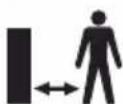
Maintain a safe distance.
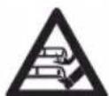
Do not touch rotating blade disk with blades.
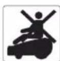
Do not climb or sit on the robot mower.

Stop the robot mower and activate the device lock during transport, storage, cleaning, servicing, repair or when there is changed or unusual behavior.

Keep children away from the robot mower and mowing area.

Keep animals away from the robot mower and mowing area.

Do not immerse the battery in liquids.

Protect battery against heat and fire.
4.2 Intended Use
The STIHL iMOW ^® 5.0 EVO, 6.0 EVO, 7.0 EVO robot mower is designed for mowing and mulching grass.
The STIHL docking station and supplied power supply DM160X-420X or DM210X-420X charge the STIHL iMOW® 5.0 EVO, 6.0 EVO, 7.0 EVO robot mower.
The robotic mower, docking station and power supply can be used in the rain.
A STIHL AAI battery supplies the robotic mower with power. The battery has been installed in the robotic mower and may only be removed by a STIHL authorized dealer.
The robotic mower can be configured and operated via the MY iMOW ^® app.
WARNING
- Docking stations, power supply units and batteries not explicitly approved for the STIHL robotic mower may cause a fire or explosion. Persons may be seriously or fatally injured, and property may be damaged.
▶ Use the robotic mower with the STIHL AAI installed battery.
▶ Charge the STIHL iMOW® 5.0 EVO, 6.0 EVO, 7.0 EVO robot mower with the STIHL docking station and STIHL power supply DM160X-420X or DM210X-420X.
■ Using the robotic mower, battery, docking station or power supply other than for its intended use can result in serious injuries or death and damage to property.
▶ Use the robotic mower, docking station and power supply as described in this User Manual.
4.3 Requirements for the user
WARNING
■ Users without adequate training or instruction cannot recognize or assess the risks involved in using the robot mower, docking station and power supply. The user or other persons may sustain serious or fatal injuries.

- Read and understand the User Manual and keep it in a safe place for reference.
▶ If you pass the robot mower, docking station or power supply on to another person: Always give them the User Manual.
▶ Make sure that the user meets the following conditions:
- The user is rested.
- The user is physically, sensorially and mentally able to use and operate the robot mower, docking station and power supply. If the user is able to operate the equipment but is physically, hearing, visually or mentally impaired, the user may only use the robot mower under the supervision of or after receiving instruction from a responsible person. This includes all work with and on the robot mower, docking station, power supply, charging cable, guide wire and perimeter wire.
- The user can recognize and assess the risks involved in using the robot mower, docking station and power supply.
- The user is an adult or is being trained in an occupation under supervision according to national regulations.
- The user has received instruction from a STIHL authorized dealer or other experienced user before using the robot mower, docking station and power supply for the first time.
- The user is not under the influence of alcohol, medication or drugs.
- During installation, operation, cleaning, maintenance and transportation of the robot mower, keep your balance, provide secure footing and do not run.
- The terms "operation", "use" and "usage" include all work on the robot mower, docking station, power supply, charging cable, guide wire and perimeter wire as well as all iMow® accessories.
4 Safety Precautions English
▶ If you are unsure: Consult a STIHL authorized dealer.
4.4 Clothing and Equipment
WARNING
■ During the routing of the perimeter wire or guide wire and attaching the docking station, objects may be thrown at high speed by driving a fixing pin or earth staple into the ground. This may result in injury to the user.
▶ Wear close-fitting safety glasses. Suitable safety glasses are tested in accordance with EN 166 or national regulations and available commercially with the corresponding marking.
▶ Wear work gloves made of robust material.
■ Objects can be ejected at high speed during the mowing operation. This may result in injury to the user.
▶ If the mowing area is entered during the mowing operation:
- Wear long pants made of robust material.
- Wear sturdy, closed-toed footwear with high-grip soles.
■ Unsuitable clothing may get caught in wood, undergrowth and in the robot mower. Users not wearing suitable clothing may be seriously injured.
▶ Wear close-fitting clothing.
▶ Remove scarves and jewelry.
■ The user may come into contact with the blades during cleaning, maintenance or transport. This may result in injury to the user.
▶ Wear work gloves made of robust material.
■ Wearing unsuitable footwear may cause the user to slip. This may result in injury to the user.
▶ If the mowing area is entered during the mowing operation: Wear sturdy, closed-toed footwear with high-grip soles.
4.5 Work Area and Surroundings
4.5.1 Robot mower and mowing area
WARNING
■ Bystanders, children and animals cannot be aware of nor assess the dangers of the robot mower and objects being thrown into the air. This may result in serious injury to bystanders, children and animals and damage to property.
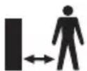
- Keep bystanders, children and animals away from the mowing area during the mowing operation.
▶ If the robot mower is used in publicly accessible areas: Close off mowing area and set up signs with warning text "Warning! Automatic lawn mower! Keep children and animals away and supervise them!" Comply with local regulations.
▶ Make sure that children cannot play with the robot mower.
- With the help of the perimeter wire, define the mowing area as described in this User Manual. Using the perimeter wire, mark off designated areas that the robot mower must not mow or navigate from the mowing area.
- Do not operate the robot mower on gravel or crushed stone.
■ People can trip over the perimeter wire, guide wire or the fixing pins. This may result in injury to people and damage to property.
- Route the perimeter wire and guide wire flat on the ground.
- Drive the fixing pins completely into the ground.
If a gardening tool is used in the mowing area, the tool can strike and damage the perimeter wire, guide wire or fixing pins. Objects can be ejected at high speed. This may result in injury to people and damage to property.
- Do not use a gardening tool around the perimeter wire or guide wire.
■ The robot mower's electrical components can produce sparks. Sparks may cause fires and explosions in highly flammable or explosive environments. Persons may be seriously or fatally injured, and property may be damaged.
- Do not operate the robot mower in highly flammable or explosive environments.
■ As a result of a storm, the robot mower can be damaged, or foreign objects may be on the mowing area. The robot mower may be in an unsafe condition, and objects may be ejected at high speed during the mowing. Persons may be seriously or fatally injured, and property may be damaged.
▶ After a storm, check that the robot mower is in a safe condition.
▶ Check the condition of the mowing area and remove any foreign objects from it.
4.5.2 Battery
The battery has been installed in the robot mower and must only be removed by a STIHL authorized dealer.
WARNING
■ Bystanders, children and animals cannot recognize or assess the dangers of the battery. Bystanders, children and animals may be seriously injured.
- Keep bystanders, children and animals away from the work area.
▶ Do not leave the battery unattended.
▶ Make sure that children cannot play with the battery.
■ The battery is not protected against all ambient conditions. If the battery is exposed to certain ambient conditions, the battery may catch fire, explode or be irreparably damaged. This may result in serious injury to people and damage to property.

▶ Protect battery from heat and fire.
▶ Do not throw the battery into a fire.
- Do not charge, use and store the battery outside of the specified temperature limits, 23.6.

- Do not immerse the battery in liquids.
- Keep battery away from small metal parts.
- Do not expose the battery to high pressure.
- Do not expose the battery to microwaves.
- Protect the battery against chemicals and salts.
4.5.3 Docking station and power supply
WARNING
■ Bystanders, children and animals are not aware of and cannot assess the dangers of the docking station or power supply. Bystanders, children and animals may be seriously or fatally injured.
- Keep bystanders, children and animals away from the work area.
▶ Make sure that children cannot play with the docking station or power supply.
■ The docking station and the power supply are not protected against all environmental conditions. If the docking station and power supply are exposed to certain environmental conditions, they may catch fire or explode. This may result in serious injury to people and damage to property.
- Do not operate the docking station and power supply in a flammable environment or explosive environment.
- Do not use or store the docking station and power supply outside of their specified temperature limits, 123.6.
- Disconnect the power supply before a storm or when there is a risk of a lightning strike.
■ People can trip over the docking station, charging cable, power supply or connecting cable. People can be injured, and the docking station, charging cable, power supply or connecting cable can be damaged.
▶ Set up the docking station and power supply in a clearly visible area.
- Route the connecting cable and charging cable flat on the ground.
■ The housing of the power supply can get very hot in direct sunlight. There is a risk of burn injuries.
▶ Do not touch a hot power supply.

4.6 Safe Condition
4.6.1 Robot mower
The robot mower is in a safe condition if the following conditions are met:
– The robot mower is undamaged.
- The controls function properly and have not been modified.
- The blades are properly installed and are undamaged.
- Original STIHL accessories designed for this robot mower are installed.
- The accessories are correctly installed.
WARNING
■ If not in safe condition, components may no longer operate correctly and safety devices may be rendered ineffective. There is a risk of serious or fatal injury.
▶ Operate an undamaged and functioning robot mower.
▶ Do not modify the robot mower.
▶ If the control panel is not functioning: Do not operate the robot mower.
▶ Install original STIHL accessories designed for this robot mower.
- Install the blades as described in this User Manual.
▶ Install accessories as described in this User Manual or in the User Manual for the accessories.
- Do not insert objects in the robot mower's openings.
4 Safety Precautions English
- Do not bridge charging contacts with metallic objects (short circuit).
- Replace worn or damaged labels.
▶ If you are unsure: Consult a STIHL authorized dealer.
4.6.2 Blades
The blades are in a safe condition if the following conditions are met:
- The blades, blade disk and blade carrier are undamaged.
– The blades are not deformed. - The blades are properly installed.
WARNING
■ If they are in an unsafe condition, parts of the blades may come off and be ejected at high speed. People may be seriously injured.
▶ Work with undamaged blades and an undamaged blade disk and blade carrier.
▶ Install blades correctly.
▶ If you are unsure: Consult a STIHL authorized dealer.
4.6.3 Battery
The battery has been installed in the robot mower and must only be removed by a STIHL authorized dealer.
The battery is in a safe condition if the following points are observed:
- Battery is undamaged.
- The battery is clean and dry.
- Battery functions properly and has not been modified.
WARNING
■ A battery that is not in a safe condition cannot operate safely. Persons may be seriously injured.
▶ Never work with a damaged battery.
▶ Never attempt to charge a damaged or defective battery.
▶ If the battery is dirty: Clean the battery.
▶ If the battery is moist or wet: Allow the battery to dry.
▶ Never attempt to modify the battery.
- Never insert objects in the battery's openings.
▶ Never bridge the battery's contacts with metallic objects (short circuit).
▶ Do not open the battery.
- Replace worn or damaged labels.
■ Fluid may leak from a damaged battery. If that liquid comes into contact with the skin or eyes, the skin or eyes may be irritated.
- Avoid contact with the liquid.
▶ If skin contact occurs: Wash affected areas of skin with plenty of water and soap.
▶ In the event of contact with eyes: Rinse eyes with plenty of water for at least 15 minutes and consult a doctor.
■ A damaged or defective battery may smell unusual, emit smoke or burn. Persons may be seriously or fatally injured, and property may be damaged.
▶ If the battery smells unusual or emits smoke: do not use the battery and keep it away from combustible substances.
▶ If the battery catches fire: Attempt to extinguish the battery with a fire extinguisher or water.
4.6.4 Docking station, charging cable, power supply and connecting cable
The docking station, charging cable, power supply, connecting cable and plug connections are in a safe condition if the following conditions are met:
- The docking station, charging cable, power supply, connecting cable and plug connections are undamaged.
- The docking station, charging cable, power supply, connecting cable and plug connections are clean.
- Original STIHL accessories designed for this docking station are installed.
– The accessories are correctly installed. - Docking station and power supply are not covered during operation.
WARNING
■ If not in a safe condition, components may no longer operate safely and safety devices may be rendered ineffective. There is a risk of serious or fatal injury.
▶ Use an undamaged docking station, charging cable, power supply, connecting cable and plug connections.
▶ If the docking station, power supply or plug connections are dirty: Clean them.
▶ Do not modify the docking station, charging cable, power supply, connecting cable and plug connections.
- Do not insert objects into the openings of the docking station and power supply.
▶ Do not bridge the electrical contacts of the docking station, power supply and plug connections with metallic objects (short circuit).
- Do not open the docking station and power supply.
- Do not cover the docking station and power supply.
English 4 Safety Precautions
- Do not bury the power supply in the ground.
▶ Do not sit on the docking station. - Do not stand on the base plate of the docking station.
4.7 Mowing operation
WARNING
■ The blades on the rotating blade disk can cut the user. This may result in serious injury to the user.
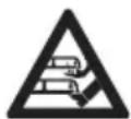
- Do not touch rotating blade disk and blades.
▶ If the user approaches the robot mower during the mowing operation or before they want to make adjustments on the device: Press the STOP pushbutton.
▶ Do not tilt or lift the robot mower during the mowing operation.
▶ If the blade disk or blades are blocked by an object: Stop the robot mower and activate the device lock. Only then remove the object.
- Keep children away from the robot mower and mowing area.

- Keep animals away from the robot mower and mowing area.

▶ Do not climb or sit on the robot mower. Do not transport children, animals or objects on the robot mower.
■ If the behavior of the robot mower changes during operation or feels unusual, it may no longer be in a safe condition. This may result in serious injury to people and damage to property.
- Press the STOP pushbutton and activate the device lock. Contact a STIHL authorized dealer.
If the blades hit a foreign object during the mowing operation, the blades or parts of them can be damaged or ejected at high speed. This may result in injury to people and damage to property.
- Remove foreign objects from the mowing area.
- Remove broken off blades or parts of blades from the mowing area.
■ When the STOP pushbutton is pressed, the blade disk with the blades will continue to rotate for a short time. People may be seriously injured.
- Wait until the blade disk is no longer rotating.
■ If the blades hit a hard object during the mowing operation, sparks can be produced and the blades can be damaged. Sparks can cause fires in a flammable environment. Persons may be seriously or fatally injured, and property may be damaged.
▶ Do not use in a flammable environment.
▶ Make sure that the blades are in a safe condition.
DANGER
■ If the robot mower is operating near live electric cables, the blades can come in contact with the cables and damage them. There is a risk of serious or fatal injury.
- Do not operate the robot mower in the vicinity of live cables.
4.8 Charging
WARNING
■ A damaged or defective power supply may produce an unusual smell or emit smoke during the charging process. This may result in injury to people and damage to property.
- Disconnect the mains plug from the wall socket.
■ The power supply can overheat and cause a fire if heat dissipation is inadequate. Persons may be seriously or fatally injured, and property may be damaged.
▶ Do not cover the power supply.
4.9 Connecting to the power supply
Contact with live components may occur for the following reasons:
- The connecting cable or the extension cord is damaged.
- The mains plug of the connecting cable or extension cord is damaged.
- The socket is not properly installed.
DANGER
■ Contact with live parts may result in electric shock. This may result in serious or fatal injury to the user.
▶ Check that the wires and their mains plugs are undamaged.
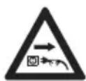
If the connecting cable or the extension cord is damaged:
▶ Do not touch the damaged area.
- Disconnect the mains plug from the wall socket.
e your hands are dry before touching es and their mains plugs.
4 Safety Precautions English
- Insert mains plugs only in a properly installed and fused wall socket.
▶ If the wall socket is outside of a building: Make sure that the socket is approved for outdoor use.
▶ Install the power supply with a fault current circuit breaker (30 mA, 30 ms).
▶ If the connecting cable or extension cable is connected or disconnected, always grip the plug and do not pull on the cable.
■ A damaged or unsuitable extension cable can result in electric shock. There is a risk of serious or fatal injury.
▶ Use an extension cable with the correct cable cross-section, ☐23.5.
▶ Use a splash water protected extension cable approved for outdoor use.
▶ Protect plug connection between the power supply and extension cable against water.
▶ Use an extension cable with the same specifications as the power supply's connecting cable.
WARNING
■ An incorrect line voltage or mains frequency can result in an overvoltage in the power supply. The power supply may be damaged.
- Make sure the line voltage and mains frequency match the data on the power supply's rating label.
■ If the power supply is connected to a power strip, electrical components may be overloaded during the charging process. The electrical components may overheat and cause a fire. Persons may be seriously or fatally injured, and property may be damaged.
▶ Ensure that the technical specifications for the power strip are not exceeded by the information on the rating plate of the power supply and of all electrical devices connected to the power strip.
■ An improperly routed connecting cable, extension cable or charging cable can be damaged and cause people to trip over them. This may result in serious injury to people and damage to property.
- Route the wires and charging cable so that they are outside of the mowing area.
▶ Route and mark the wires and charging cable so that they will not be damaged by work with a gardening device or tool. -
Route and mark the wires and charging cable in such a way that people cannot trip over them.
-
Route the wires and charging cable in such a way that they are not under tension or tangled.
- Route the wires and charging cable in such a way that they will not be damaged, bent, crushed or will not chafe.
- Protect the wires and charging cable from heat, oil and chemicals.
- Route the wires and charging cable so that they are not on a permanently wet surface.
■ If electrical wiring and conduits are routed in the wall, they may be damaged if the power supply is mounted on the wall. Contact with wiring can result in electric shock. This may result in serious injury to people and damage to property.
▶ Make sure there is no electrical wiring or conduits in the wall at the proposed mounting site.
▶ Mount the power supply on a wall as described in this User Manual.
■ If the power supply is connected to a generator, the electricity supply cannot be permanently ensured and the robot mower may not function properly. The power supply may be damaged by fluctuations in the electricity supply.
▶ Only connect the power supply to a properly installed socket.
4.10 Transporting
4.10.1 Robot mower
WARNING
■ The robot mower may tip over or move during transport. This may result in injury to people and damage to property.
- Stop the robot mower and activate the device lock.
- Secure the robot mower with lashing straps, belts or a net so that it cannot tip over or move.
4.10.2 Battery
The battery has been installed in the robot mower and must only be removed by a STIHL authorized dealer.
WARNING
■ The battery is not protected against all environmental conditions. The battery may be damaged if it is exposed to certain ambient
English 4 Safety Precautions
conditions, and damage to property may occur.
▶ Never transport a damaged battery.
■ The battery may turn over or shift during transport. Persons may be injured, or property may be damaged.
- Pack the battery in packaging in such a way that it cannot move.
- Secure the packaging so that it cannot move.
4.10.3 Docking station and power supply
WARNING
■ The docking station or power supply may tip over or move during transport. This may result in injury to people and damage to property.
- Disconnect the mains plug from the wall socket.
- Remove the robot mower from the docking station.
- Secure the docking station and power supply with lashing straps, belts or a net to ensure that they cannot tip over or move.
■ The connecting cable and charging cable are not intended to carry the weight of the power supply or docking station. The connecting cable, power supply, charging cable or docking station may be damaged.
- Disconnect the charging cable from the power supply and docking station and coil it.
▶ Grip the docking station by the base plate and hold it firmly.
- Wind up the connecting cable and attach it to the power supply.
▶ Grip the power supply by the housing and hold it firmly.
4.11 Storing
4.11.1 Robotic Mower
WARNING
■ Children are not aware of and cannot assess the dangers of the robot mower. Children may be seriously injured.

- Stop the robot mower and activate the device lock.
- Store the robot mower out of the reach of children.
■ Moisture may cause the electrical contacts on the robot mower and metal components to corrode. The robot mower may be damaged.
- Store the robot mower in a clean and dry condition.
■ The robot mower may start unintentionally and begin to move if its device lock is not activated before storage. This may result in serious injury to people and damage to property.
- Stop the robotic mower and activate the device lock.
■ The hood and handles are not intended to be used to hang up the robotic mower. Safety devices may be rendered inoperative, and the robot mower may be damaged.
- Store the robotic mower as described in this User Manual.
4.11.2 Battery
The battery has been installed in the robot mower and must only be removed by a STIHL authorized dealer.
WARNING
■ Children are not aware of and cannot assess the dangers of the battery. Children may be seriously injured.
- Store the battery out of the reach of children.
■ The battery is not protected against all ambient conditions. If the battery is exposed to certain ambient conditions, the battery may be irreparably damaged.
- Store the battery in a clean and dry condition.
- Store the battery in an enclosed space.
▶ Do not store the battery outside of the specified temperature limits, 23.6.
4.11.3 Docking station and power supply
WARNING
■ Children are not aware of and cannot assess the dangers of a docking station or power supply. Children can be seriously injured or killed.
- Remove the robot mower from the docking station.
- Store the docking station and power supply out of the reach of children.
■ The docking station and the power supply are not protected against all environmental conditions. If the docking station and power supply are exposed to certain environmental conditions, they may be damaged.
- Remove the robot mower from the docking station.
5 Description of Operation English
▶ If the power supply is hot: Allow the power supply to cool down.
- Store the docking station and power supply in a clean and dry condition.
- Store the docking station and power supply in an enclosed space.
- Do not store the power supply outside of the specified temperature limits, 123.6.
■ The connecting cable and charging cable are not intended to carry the weight of the power supply or docking station. The connecting cable, power supply, charging cable or docking station may be damaged.
- Disconnect the charging cable from the power supply and docking station and coil it.
▶ Grip the docking station by the base plate and hold it firmly. - Wind up the connecting cable and attach it to the power supply.
▶ Grip the power supply by the housing and hold it firmly.
4.12 Cleaning, maintenance and repair
WARNING
■ The robot mower may start unintentionally if the device lock is not activated during cleaning, maintenance or repair operations. This may result in serious injury to people and damage to property.

- Stop the robot mower and activate the device lock.
■ Harsh detergents or cleaning with a high pressure washer or sharp metallic objects can damage the robot mower. If the robot mower is not cleaned correctly, components may no longer function properly or safety devices may be rendered inoperative. People may be seriously injured.
- Clean the robot mower as described in this User Manual.
■ Harsh detergents or cleaning with a high pressure washer or sharp metallic objects can damage the docking station, power supply, connecting cable, charging cable and plug connections. If the docking station, power supply, connecting cable, charging cable or their plug connections are not cleaned correctly, components may no longer function properly or safety devices may be rendered inoperative. People may be seriously injured.
- Disconnect the power supply's mains plug from the wall socket.
- Clean the docking station, power supply, connecting cable, charging cable and their plug connections as described in this User Manual.
■ If the robot mower, docking station or power supply are not serviced or repaired correctly, components may no longer function properly or safety devices may be rendered inoperative. There is a risk of serious or fatal injury.
- Do not service or repair the robot mower, docking station and power supply yourself.
▶ If the robot mower, docking station or power supply require servicing or repairs: Contact a STIHL authorized dealer. - Maintain the blades as described in this User Manual.
■ The user can be cut by the sharp cutting edges of the blades while cleaning or servicing the mowing unit. This may result in injury to the user.
▶ Wear work gloves made of robust material.
■ If the power supply's connecting cable is faulty or damaged:
▶ Replace power supply.
■ If the plug of the diagnostic socket on the bottom of the robot mower does not fit correctly, moisture and dirt can penetrate the robot mower. The robot mower may be damaged.
▶ Check the fit of the plug during each cleaning and blade change.
- Do not operate the robot mower with a missing or damaged plug.
5 Description of Operation
5.1 Functional Description
flowchart
graph TD
    A["1"] --> B["2"]
    B --> C["3"]
    C --> A
    style A fill:#f9f,stroke:#333
    style B fill:#ccf,stroke:#333
    style C fill:#cfc,stroke:#333
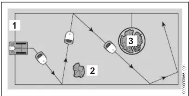
The robot mower mows the grass in randomly selected paths. It is necessary to route a perimeter wire (1) so the robot mower can identify the boundaries of the mowing area.
The perimeter wire (1) transmits a signal to the robot mower. The signal is generated by the docking station.
English 5 Description of Operation
The robot mower identifies fixed obstacles (2) in the mowing area using ultrasound sensors and a bump sensor.
If the robot mower identifies a fixed obstacle (2), it will slow down, bump into the fixed obstacle and then continue to move in a different direction.
Areas (3) the robot mower must not navigate and obstacles it must not come into contact with must be blocked off from the remaining mowing area with the help of the perimeter wire (1).
If the robot mower identifies a blocked-off area (3), it will slow down and then continue to move in a different direction.
In mowing operation, the robotic mower leaves the docking station by itself and mows the lawn.
The robotic mower is operated by the MY iMOW® app and the buttons in the control panel on the robotic mower. Light strips and the matrix display on the robotic mower as well as an artificially generated voice output provide information about the current status of the robotic mower.
flowchart
graph TD
    A["Vehicle"] --> B{Decision}
    B -->|Yes| C["Car"]
    B -->|No| D["Circular Object"]
    C --> E["Arrow to Car"]
    D --> F["Arrow to Car"]
    style D stroke-dasharray: 5 5
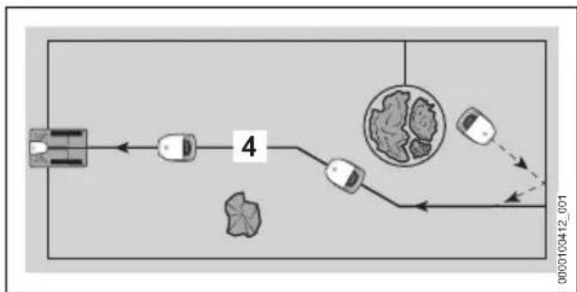
If the battery's state of charge is low, the robotic mower will search for the nearest guide wire (4) during the mowing operation. If a guide wire (4) is recognized, the robotic mower will return to the docking station by itself. The docking station recharges the battery. At least one guide wire (4) must be installed in the mowing area. A maximum of three guide wires can be installed. If the mowing operation is canceled or the battery must be charged, the robotic mower can be sent directly back to the docking station using the MY iMOW® app or HOME pushbutton.
flowchart
graph TD
    A["Start"] --> B["Step 5"]
    B --> C["Step 4"]
    C --> D["Step 4"]
    D --> E["Step 5"]
    style A fill:#f9f,stroke:#333
    style B fill:#ccf,stroke:#333
    style C fill:#cfc,stroke:#333
    style D fill:#fcc,stroke:#333
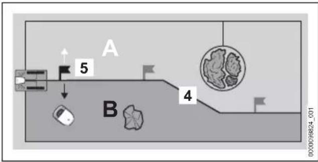
Up to three starting points (5) can be specified on a guide wire (4). The robotic mower can move specifically to the respective starting point and start mowing from there.
The mowing area can be divided into several zones (example: A and B) by the guide wire (4). The zones are defined by a starting point (5). The robotic mower can be directed from the selected starting point to the left or right into the desired zone. The robotic mower can then mow specifically in the selected zone. The starting points and zones are managed in the MY iMOW® app and can be taking into account in the mowing plan.
flowchart
graph TD
    A["Start"] --> B["Step 6"]
    B --> C["Step 7"]
    C --> D["Step 8"]
    D --> E["End"]
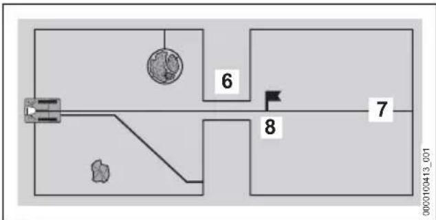
If there is a confined section (6) in the mowing area, the robotic mower navigates the confined area, provided that a particular minimum width is maintained between the perimeter wires. If the minimum distance cannot be maintained, a guide wire (7) must be routed through the confined section (6). The guide wire (7) then guides the robotic mower directly through the confined section (6) to a starting point (8). From the starting point (8), the robotic mower can mow the mowing area behind the confined section (6). The frequency at which the robotic mower returns to the starting point (8) can be managed by the MY iMOW® app and taken into account in the mowing plan.
6 Preparing the Mowing Area and Robot Mower for Operation
6.1 Planning and preparing mowing areas
Plan and prepare the mowing area prior to commissioning the robot mower. This enables a robust installation and smooth operation and eliminates potential sources of faults.
Planning mowing surfaces
▶ Familiarize yourself with the descriptions about the docking station and wire routing in the following sections.
▶ Transfer the information to your own garden:
– Outline of the mowing area
- Position of the docking station
- Routing of the perimeter wire (note described distances to the edges and wire routing cases)
- Routing of the guide wire(s) (at least one, maximum of three)
Preparing mowing areas
text_image
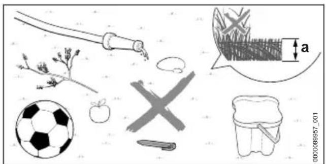
Illustration showing various objects and symbols including a soccer ball, apple, pencil, brush, and a cross symbol with an arrow labeled 'a'▶ Remove any objects lying around.
- Remove metals, magnetic materials and materials that conduct electricity as well as old perimeter wires.
▶ Mow lawns with a lawn mower to the cutting height that will later be set for the operation of the robot mower. The default setting for the cutting height on the robot mower is a = 6 cm.
▶ Level out holes and rough, uneven patches.
▶ Where ground is hard and dry, slightly moisten the mowing area to make driving the anchoring stakes easier.
natural_image
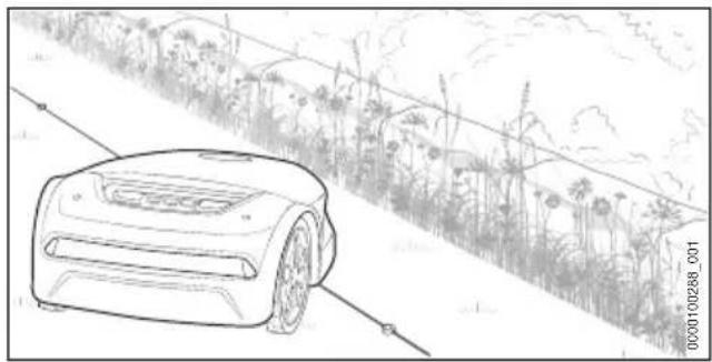
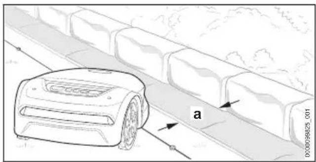
Line drawing of a robotic lawn mower on a road with grassy background (no text or symbols)As a result of its design, the robot mower leaves a strip with unmown lawn along unnavigable areas. This strip can be used, for example, to sow flower seeds and create areas with blossoming vegetation for insects.
text_image
a 000009825_001▶ If you want to mow without leaving an edge along inaccessible areas: Install edging stones or flagstones with a minimum width of a = 24 cm along these areas.
6.2 Preparing the robot mower for operation
- Remove the packaging material and transport locks.
- Ensure that the following components are in a safe condition:
- Robot mower, 04.6.1
- Blades, 24.6.2
- Battery, 4.6.3
- Docking station and power supply, 4.6.4
▶ Positioning the docking station, 📄 7
- Installing the perimeter wire, 18
- Completing the perimeter wire installation, 9.1
- Installing the guide wire, 10.1
▶ Electrically connecting the docking station, 11.1
▶ Charging the robot mower, 12.1
- Locking the Bluetooth® radio interface, 13.1
▶ If you cannot carry out these steps: Do not use the robot mower and contact a STIHL authorized dealer for assistance.
7 Positioning the docking station
7.1 General requirements
text_image
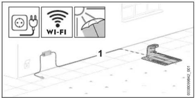
000009842_001 1 WI-FI▶ Choose the docking station location so that the following conditions are met:
- The charging cable (1) can be installed outside of the mowing area to connect to a suitable wall socket.
- The docking station and power supply are positioned in a clearly visible area.
- The docking station is in the mowing area that is the largest or most frequently mowed.
- If possible, protect the location against adverse weather conditions and direct sunlight.
- If possible, the docking station is within range of a wireless network (WLAN connection).
- If possible, in a mowing area with a slope, the docking station is in the lower area of the slope.
text_image
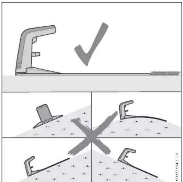
Diagram illustrating three different types of tool positioning: check, cross, and planar, with labeled parts and a watermark.- Align the docking station so that the following conditions have been met:
- The docking station has been positioned on a level surface.
- The opening of the docking station is facing forward toward the mowing area.
- The docking station has been aligned horizontally and is not tilted to the side, the front or the rear.
- The base plate does not sag and lies flat on the ground.
7.2 Positioning the docking station
The correct position of the docking station depends on the planned location and its surroundings.
▶ Select the location and set up the docking station as described.
Positioning the docking station within the mowing area
text_image
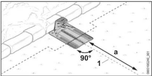
90° 1 a 0000100240_001The docking station is at the edge of the mowing area by a wall and the guide wire (1) can be routed for a =2 m in a straight line from the docking station to the mowing area.
text_image
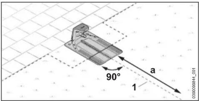
90° a 1 000009844_001The docking station is at the edge of the mowing area. The adjacent area is navigable and the guide wire (1) can be routed for a =2 m in a straight line from the docking station to the mowing area.
7 Positioning the docking station English
text_image
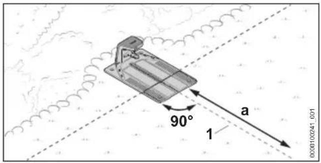
90° a 1 0000100241_001The docking station is partially in a bed and partially on the mowing area and the guide wire (1) can be routed for a =2 m in a straight line from the docking station to the mowing area.
text_image
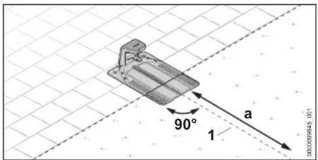
90° 1 a 000009845.00-1The docking station is partially in the mowing area and the guide wire (1) can be routed for a =2 m in a straight line from the docking station to the mowing area.
▶ Prepare the docking station, 17.3.
▶ Setting up the docking station in a mowing area, ☐7.4.
Setting up the docking station outside the mowing area
text_image
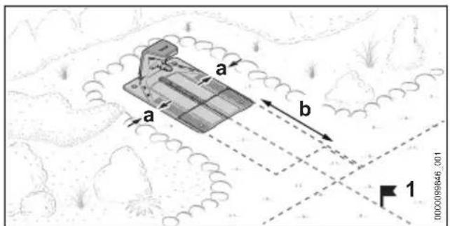
a a b 1 0000089646_001The docking station is outside the mowing area.
The minimum lateral distance toward adjacent areas must be at least a = 15 cm.
The minimum distance between the front edge of the docking station and the mowing area must be at least b = 2 m.
With this variant, it is mandatory to define a starting point (1) within the mowing area at the conclusion of commissioning. The robotic mower then starts mowing from this point and not
directly from the docking station. Starting points can be set using the MY iMOW® app. The approach frequency of the starting point (1) must be set in the app at 100%.
▶ Prepare the docking station, 7.3.
▶ Setting up the docking station outside the mowing area, ☐7.5.
Setting up the docking station in the center of the mowing area
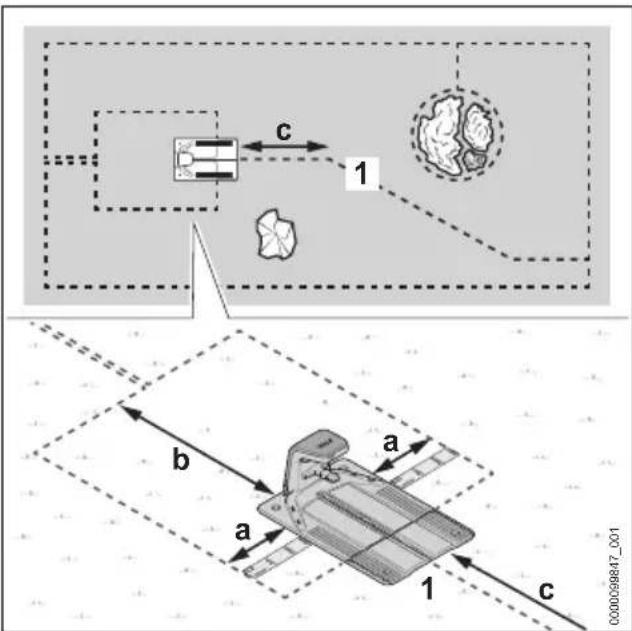
text_image
Technical diagram illustrating a mechanical or fluid system with labeled components and directional arrows, including annotations 1 and c.The docking station is positioned as an island in the center of the mowing area.
With this variant, the perimeter wire is routed around the docking station toward the rear and the edge of the mowing area. The guide wire is routed toward the front to the edge of the mowing area.
The minimum lateral distance to adjacent areas must be at least a = 37 cm (length: 1x iMOW® Ruler).
The minimum distance between the rear edge of the docking station and the edge of the mowing area must be b = 2 m.
It must be possible to route the guide wire (1) for c = 2 m in a straight line from the docking station to the mowing area.
▶ Prepare the docking station, 7.3.
▶ Set up the docking station in the center of the mowing area, 17.6.
English 7 Positioning the docking station
7.3 Preparing the docking station
Connecting the charging cable.
NOTICE
In assembled condition, the plug connections of the charging cable are protected against contamination, e.g. dust and dirt. Contamination of the plug connections may result in breakdowns of the docking station.
- Protect open plug connections against contamination.
- Clean the contaminated plug connections as described in this User Manual.
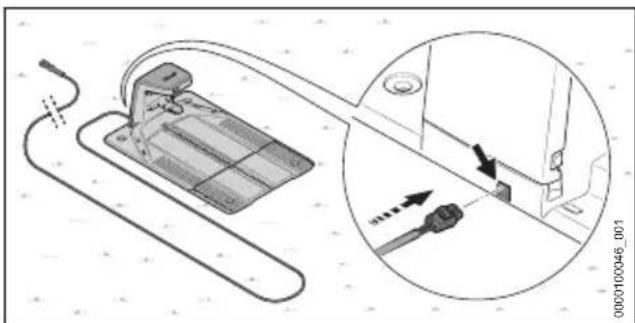
natural_image
Diagram showing a device with cable and connector, connected to a close-up view of a mechanical component (no text or symbols present)Normally the charging cable is connected from the rear.
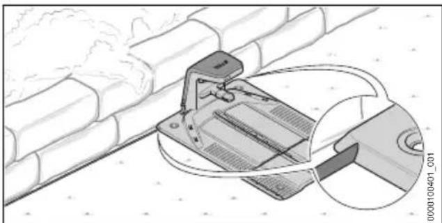
natural_image
Diagram of a mechanical device with a handle and cable, showing internal components and a magnified inset (no text or symbols)If the docking station has been positioned directly against a wall, it is also possible to install the charging cable under the base plate. The charging cable can be routed out of the base plate to the left or right.

text_image
1 000098854_001▶ Slightly bend the hood (1) toward the outside on both sides and remove it upward.
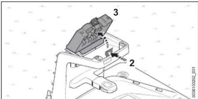
text_image
Technical diagram of a mechanical assembly with labeled components 2 and 3, showing internal components and directional arrows.▶ Press the retaining latch (2) and open the cover (3).
text_image
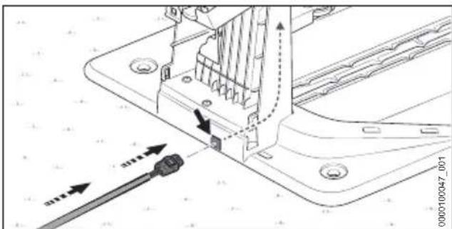
Technical diagram showing mechanical assembly with labeled components and directional arrows indicating movement or force▶ If you intend to connect the docking station from the rear:
▶ Insert the plug (4) into the conduit (5) and feed the charging cable (6) through. Push the charging cable (6) upward inside the docking station.
text_image
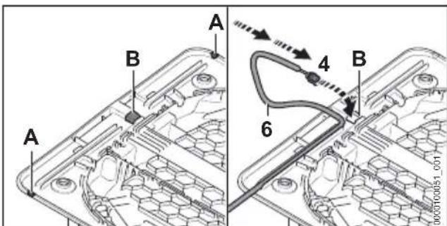
A B A 4 B 6 1000000000-09▶ If the docking station has been positioned directly against a wall or you want to route the charging cable underneath the base plate toward the side:
▶ Open the edge and deburr it on the desired side of the base plate at position (A).
▶ Cut out and deburr an opening in the center of the base plate (B).
- Insert the plug (4) into the opening (B) and feed the charging cable (6) through.
Push the charging cable (6) upward inside the docking station.
7 Positioning the docking station English
text_image
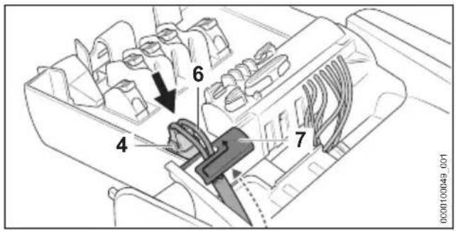
Technical diagram of a mechanical device with numbered components and directional arrows indicating flow or movement.- Secure the charging cable (6) in the cable holder (7).
▶ Insert the plug (4). The plug (4) audibly and noticeably engages on both sides.
Securing the docking station
natural_image
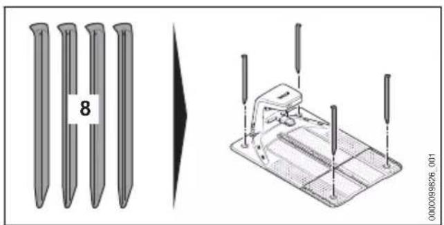
Technical illustration of a mechanical device with pins and a separate view showing a pin labeled '8' (no text or symbols on the devices themselves)- Secure the docking station on the ground with four ground pegs (8).
Feeding the perimeter wire
text_image
10 9 C0008968_001- Insert the beginning of the wire (9) into the right conduit (10) and feed it through. Push the perimeter wire (9) upward inside the docking station.
text_image
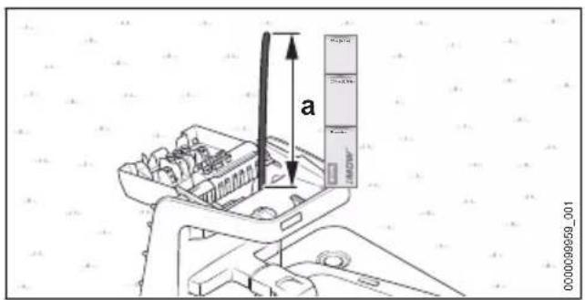
a 0000099959_001▶ Feed the perimeter wire through until it protrudes upward for a = 37 cm (length: 1x iMOW® Ruler).
text_image
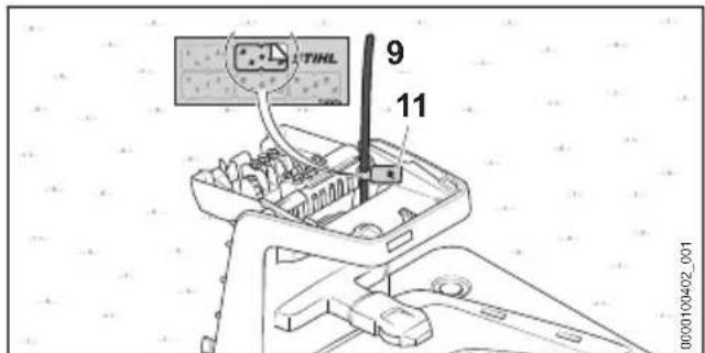
9 11 0000100402_001▶ Using the appropriate cable marker (11), mark the beginning of the wire (9) near the housing. Marking will facilitate the subsequent connection to the correct terminal.
7.4 Positioning the docking station within the mowing area
text_image
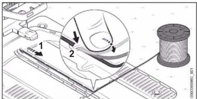
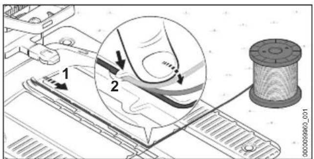
Technical diagram showing mechanical assembly with labeled parts and a magnified detail view of a fiber or fiber connection.▶ Install the perimeter wire (1) in the base plate so that the guide wire lies flat in the cable duct and is secured by the hook (2).
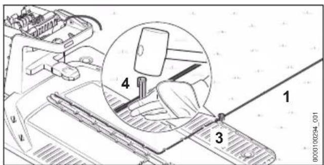
text_image
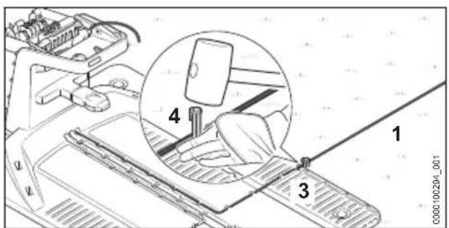
1 2 3 4 0000100294_001- Attach the perimeter wire (1) directly on the base plate (3) with a fixing pin (4).
If the docking station is against a wall:
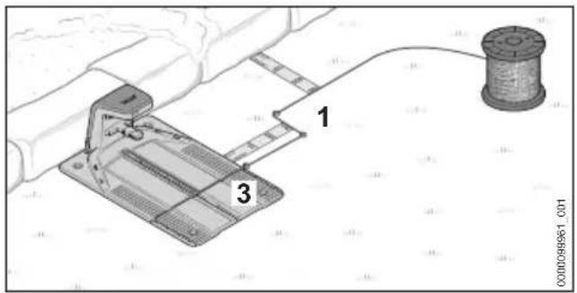
text_image
1 3 00005961_001- Route the perimeter wire (1) 37 cm (length: 1x iMOW® Ruler) away from the base plate (3) toward the side.
- Route the perimeter wire (1) in parallel to the base plate (3) toward the edge of the mowing area and maintain a distance from the wall of 37 cm (length: 1x iMOW® Ruler).
- Route the perimeter wire (1) clockwise around the mowing area, 8.
If the docking station is in an adjacent, navigable area:
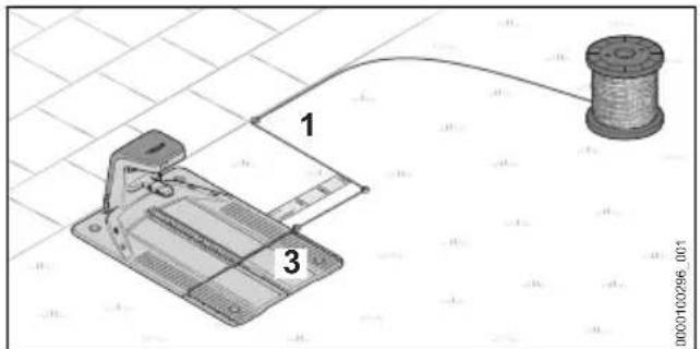
text_image
1 3 000010296_001- Route the perimeter wire (1) 37 cm (length: 1x iMOW® Ruler) away from the base plate (3) toward the side.
- Route the perimeter wire (1) in parallel to the base plate (3) toward the edge of the mowing area.
- Route the perimeter wire (1) clockwise around the mowing area, 8.
If the docking station is partly positioned in a bed and partly in the mowing area:
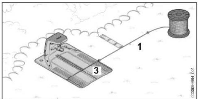
text_image
Diagram of a mechanical device with labeled parts and connection points, including a wire spool and coil.- Route the perimeter wire (1) away from the base plate (3) toward the side and maintain a distance of 37 cm (length: 1x iMOW® Ruler) in parallel to the bed.
- Route the perimeter wire (1) clockwise around the mowing area, 8.
If the docking station has been positioned partly in a navigable area and partly in the mowing area:
text_image
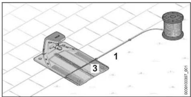
Diagram of a mechanical device with labeled parts 1, 2, and 3, connected to a spool on a grid background.- Route the perimeter wire (1) away from the base plate (3) toward the side and along the navigable area.
- Route the perimeter wire (1) clockwise around the mowing area, 8.
7.5 Setting up the docking station outside the mowing area
text_image
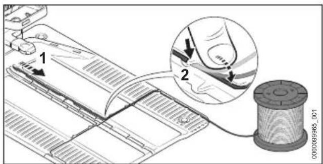
1 2 000089565_001▶ Install the perimeter wire (1) in the base plate so that the guide wire lies flat in the cable duct and is secured by the hook (2).
text_image
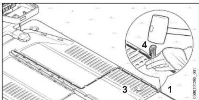
Technical diagram showing a mechanical assembly with numbered components and an inset view of a hand holding a device labeled 4.▶ Attach the perimeter wire (1) directly on the base plate (3) with a fixing pin (4).
7 Positioning the docking station English
text_image
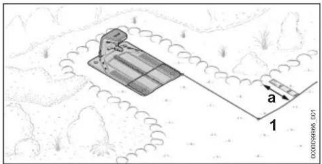
a 1 000009866_001- Route the perimeter wire (1) toward the front to the mowing area.
The correct distance to the edge of the mowing area depends on whether the edge of the mowing area is navigable, or a distance of a = 37 cm (length: 1x iMOW® Ruler) needs to be maintained. - Route the perimeter wire (1) clockwise around the mowing area, 8.
7.6 Setting up the docking station in the center of the mowing area
text_image
Technical diagram showing mechanical assembly with labeled parts and a magnified inset highlighting a component detail.▶ Install the perimeter wire (1) in the base plate so that the guide wire lies flat in the cable duct and is secured by the hook (2).
text_image
Technical diagram showing a mechanical assembly with numbered components and a magnified inset view labeled 4- Attach the perimeter wire (1) directly on the base plate (3) with a fixing pin (4).
text_image
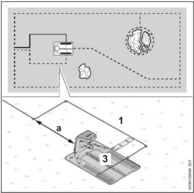
Technical diagram showing a mechanical assembly with labeled components and a schematic of a device with parts 1 and 3.- Route the perimeter wire (1) at least 37 cm (length: 1x iMOW® Ruler) away from the base plate (3) toward the side.
▶ Route the perimeter wire (1) at least a = 2 m behind the base plate (3). - Route the perimeter wire (1) in the center behind the docking station toward the edge of the mowing area.
Maintain the correct distance to the edge of the mowing area depending on the adjacent area. - Route the perimeter wire (1) clockwise around the mowing area, 8.
8 Installing the Perimeter Wire
8.1 General requirements
Checking routing of perimeter wire and guide wire in the mowing area
text_image
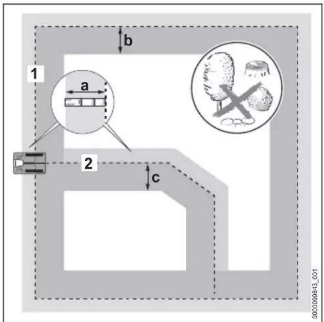
1 a b 2 c 000009843_001▶ Make sure that the mowing area along the perimeter wire and the guide wire is flat and clear of obstacles as far as possible along the following widths:
Perimeter wire (1)
- Toward the outside: a = 37 cm (length: 1x iMOW® Ruler)
- Toward the inside: b = 1.2 m
Guide wire (2)
- Toward the right in the direction of travel toward the docking station: a = 37 cm (length: 1x iMOW® Ruler)
- Toward the left in the direction of travel toward the docking station: c = 1.2 m
Installing the Perimeter Wire
▶ Install the perimeter wire clockwise starting at the docking station.
- Do not kink, cut, put tension on or cross the perimeter wire.
▶ Make sure that the perimeter wire does not cross over a guide wire.
▶ Exception: When installing a corridor, the guide wire must cross the perimeter wire.
- Keep a minimum distance of 1 m to perimeter wires of adjacent robot mower installations.
▶ Make sure that the length of the perimeter wire does not exceed 850 m.
- Do not route the perimeter wire and guide wire at different depths in the soil.
Attaching perimeter wire and guide wire
text_image
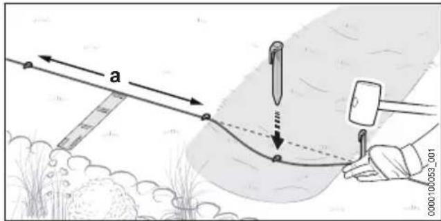
a 0000:10/053_001▶ Use anchoring stakes to secure the perimeter wire and guide wire so that the following conditions are met:
- The maximum distance between fixing pins must not exceed a = 1 m.
- The perimeter wire and guide wire lie flat on the ground in all areas.
- The anchoring stakes are sunk completely into the ground.
Installing Wire Reserves
Wire reserves make it easier to correct installed wire and give some leeway for future adaptations.
Examples:
- A bed is extended and blocked off.
- Bushes and shrubbery grow and the perimeter wire must be installed around the plants in a larger arc.
- The perimeter wire was cut too short at the docking station and cannot be connected.
One or several wire reserves can be planned and installed.
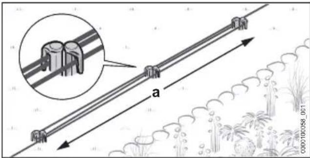
text_image
a C000100356_001▶ Route a = 1 m of perimeter wire in parallel and closely together around 2 fixing pins without the perimeter wires crossing over each over.
- Secure the wire reserve at the center using two additional fixing pins.
8 Installing the Perimeter Wire English
8.2 Planning guide wire and routing connection point in the perimeter wire
Carefully plan the routing of one or several guide wires in advance. Take into account the position of all guide wires when installing the perimeter wire. At least one guide wire must be installed; three guide wires may be installed.
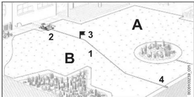
text_image
A 2 3 B 1 4 0000100239_001A guide wire (1) fulfills the following functions:
– Orientation for returning to the docking station (2)
- Moving toward a starting point (3)
– Splits the mowing area into zones (A and B)
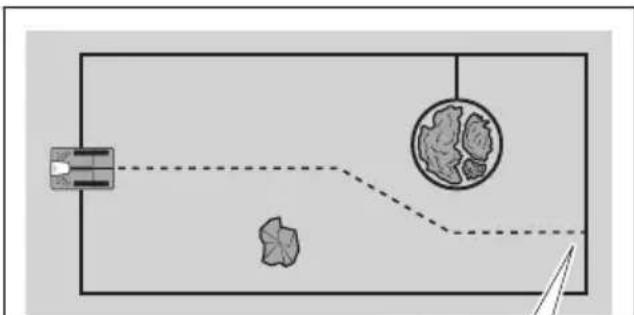
Starting at the docking station (2), install the guide wire (1) across the mowing area and connect it to a point on the circumferential perimeter wire (4) that is as far away as possible.
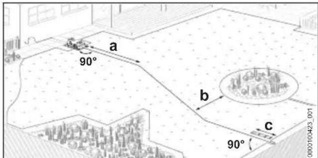
text_image
a 90° b c 90° 0000100423_001▶ Plan the guide wire so that the following conditions are met:
- Route the guide wire for a =2 m in a straight line from the docking station to the mowing area.
- The minimum distance between the guide wire and the circumferential perimeter wire is b = 27.5 cm
- Route the guide wire with a minimum distance c = 37 cm (length: 1x iMOW® Ruler) in a straight line and at a right angle to the perimeter wire and connect it.
text_image
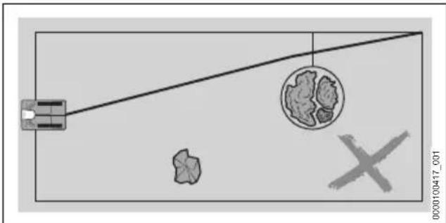
000010417_001- The guide wire must not cross over a blocked-off area connection.
- The guide wire must not be connected to the perimeter wire in a corner.
- The guide wire must not cross over a perimeter wire.
Exception: When installing a corridor, the guide wire must cross the perimeter wire. - The guide wire must not be kinked or under tension, and it must not cross over itself.
flowchart
graph TD
    A["Input Source"] --> B["Process Node"]
    B --> C["Output"]
    style A fill:#f9f,stroke:#333
    style C fill:#bbf,stroke:#333
text_image
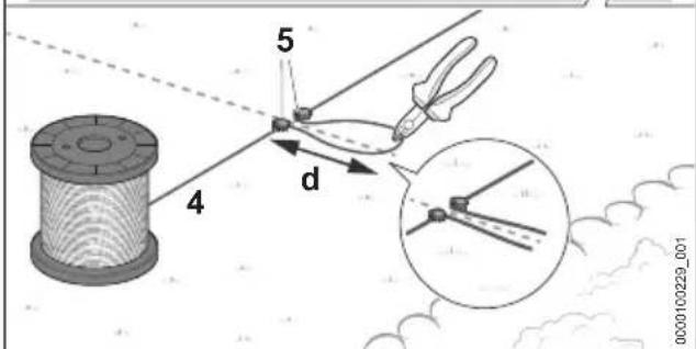
5 4 d 0000100229_001The connection point for the guide wire must be installed during the installation of the circumferential perimeter wire (4).
- Secure the perimeter wire (4) at the intended areas using a fixing pin (5).
▶ Place the perimeter wire (4) in a loop with a length of a = 15 cm and secure with another fixing pin (5).
▶ Cut the perimeter wire (4) at the end of the wire loop, such as with a wire cutter. The wire ends are connected to the guide wire at the completion of the installation. 10 - Continue to install the perimeter wire (4) around the mowing area.
English 8 Installing the Perimeter Wire
8.3 Corners
Corners with a 90° angle
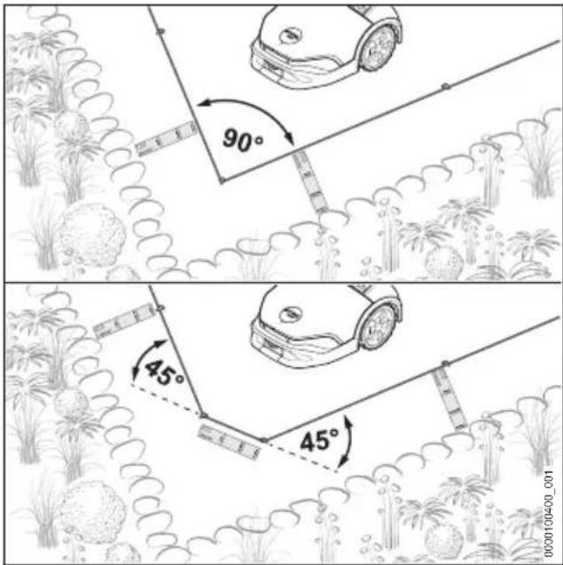
Corners with a 90^ angle can be split into two corners with a 45^ angle. Consequently, the robot mower changes its direction more smoothly and with less jerking in this area.
text_image
90° 45° 45° 0000100400_001- Route the perimeter wire in corners for at least 37 cm (length: 1x iMOW® Ruler) across the area.
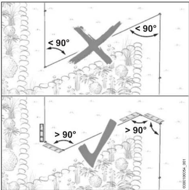
Tapered corners with an angle < 90^
Divide tapered corners with an angle < 90^ into two corners. As a result, the robot mower changes its direction more smoothly and with less jerking in this area.
text_image
< 90° > 90° > 90° 000100054_001▶ Make sure that tapered corners are not at an angle less than 90^ .
▶ If the angle is less than 90^ : Split the angle.
▶ Design one corner with an angle greater than 90°. Then route the perimeter wire in a straight line for at least 37 cm (length: 1x iMOW® Ruler).
- Then design a corner with an angle greater than 90^ . Subsequently route the perimeter wire in a straight line for at least 37 cm (length: 1x iMOW® Ruler).
8.4 Navigable area
The robot mower is able to navigate areas directly adjacent to the mowing area if the difference in height between the navigable area and the mowing area is no more than 1.5 cm. The ground must be solid and there must not be any obstacles.
Examples:
- Patio
- Paved path
- Edging stones or flagstones
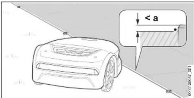
Edgeless mowing is enabled by maintaining a short distance between the perimeter wire and the navigable area.
text_image
< a 0.0010057_001▶ Route the perimeter wire parallel to and without any distance from the navigable area. The maximum difference in height between the navigable area and the mowing area is a = 1.5 cm
8.5 Unnavigable area
An area is unnavigable if obstacles close to the ground protrude into the mowing area, the ground is not solid or is very uneven and if the difference in height between the mowing area and the adjacent area is more than 1.5 cm.
Examples:
- Wall or fence
- Hedge or shrubbery with branches that grow close to the ground
- Stone garden or gravel path
- Heavily rooted or uneven ground
8 Installing the Perimeter Wire English
natural_image
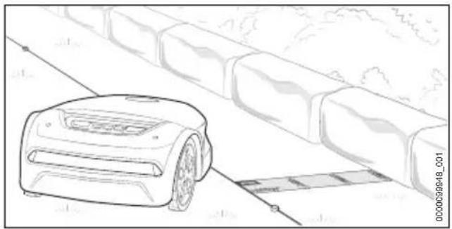
Line drawing of a robotic lawn mower on a paved path with adjacent brick barriers (no text or symbols)- Route 37 cm (length: 1x iMOW® Ruler) of perimeter wire parallel to the unnavigable area.
▶ If the unnavigable area is within the mowing area: Block off the unnavigable area with a restricted area.
8.6 Water areas
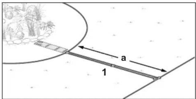
An increased wire distance must be maintained to water areas if the water area has not been blocked off from the mowing area by a fixed obstacle with a minimum height of 10 cm.
Examples:
- Garden pond
- Pool
- Stream or watercourse

text_image
a 0000100062_D01- Route the perimeter wire at a distance of a = 1 ~m in parallel to the bank area.
▶ If the water area is within the mowing area: Block off the water area with a restricted area.
8.7 Drop-off edge
Keep an increased wire distance to drop-off edges if the drop-off edge has not been blocked from the mowing area by a fixed obstacle with a minimum height of 10 cm.
Examples:
- Stairs
- Retaining wall
- Tiered slope
text_image
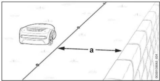
10000100063 a 10000100063▶ Route the perimeter wire at a distance of a = 1 m parallel to the drop-off edge.
8.8 Restricted area
Areas within the mowing area that must not or cannot be navigated by the robot mower must be blocked by a restricted area.
Examples:
- Bed without a fixed border with a minimum height of 10 cm
- Garden pond or pool without a fixed border with a minimum height of 10 cm
- Obstacles that the device must not come into contact with:
- Obstacles that are not strong enough
- Obstacles below a height of 10 cm
To ensure a robust mowing operation, restricted areas must not have any inwardly curved shapes.
text_image
a 1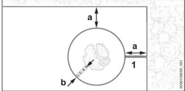
text_image
a a 1 b 0000100055.001English 8 Installing the Perimeter Wire
▶ Route the perimeter wire (1) away from the edge toward the restricted area. Make sure that the following dimensions are maintained for the restricted area:
- Minimum distance to other perimeter wires a = 55 ~cm
- Wire distance b = 37 cm (length: 1x iMOW® Ruler) (for water areas and drop-off edges, b = 1 m)
- Minimum diameter of the restricted area: 74 cm
flowchart
graph TD
    A["Cell Cycle"] --> B{Directional Flow}
    B -->|Yes| C["Path to Cell"]
    B -->|No| D["Path to Survival"]
    C --> E["Final Path"]
    D --> F["Final Survival"]
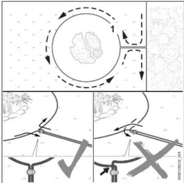
- Route the perimeter wire (1) around the area to be blocked off.
▶ Route the perimeter wire (1) parallel and close together back to the edge without the perimeter wires crossing each other.
8.9 Fixed obstacle
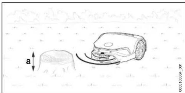
A fixed obstacle within the mowing area does not have to be blocked off by a restricted area if the obstacle is at least 10 cm high. The obstacle is identified by the ultrasound sensors and the bump sensor.
natural_image
Line drawing of a robotic arm with a tree stump and curved arm, no text or symbols present▶ A fixed obstacle with a minimum height of a = 10 cm does not need to be blocked off.
8.10 Confined section
text_image
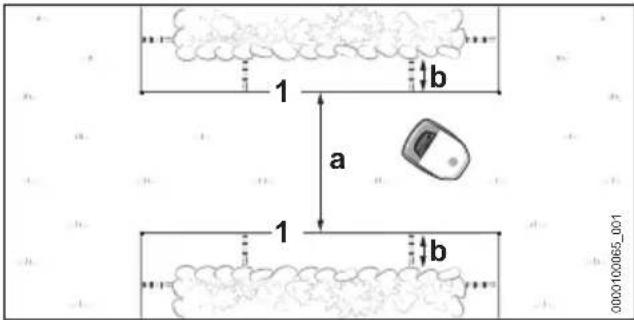
1 a 1 b 0000100065_001The robot mower navigates all confined areas, provided that a minimum width (a) is maintained between the perimeter wires (1).
- Route the perimeter wire (1) as illustrated and make sure that the following dimensions have been maintained:
- Minimum distance between the perimeter wires (1) in the confined section: a = 2 ~m
- If the confined section is restricted by side obstacles: Include an additional distance of b = 37 cm (length: 1x iMOW® Ruler)
▶ If the minimum distance a = 2 m between the perimeter wires (1) cannot be maintained: Route a guide wire through the middle of the confined section.
Confined section with guide wire
text_image
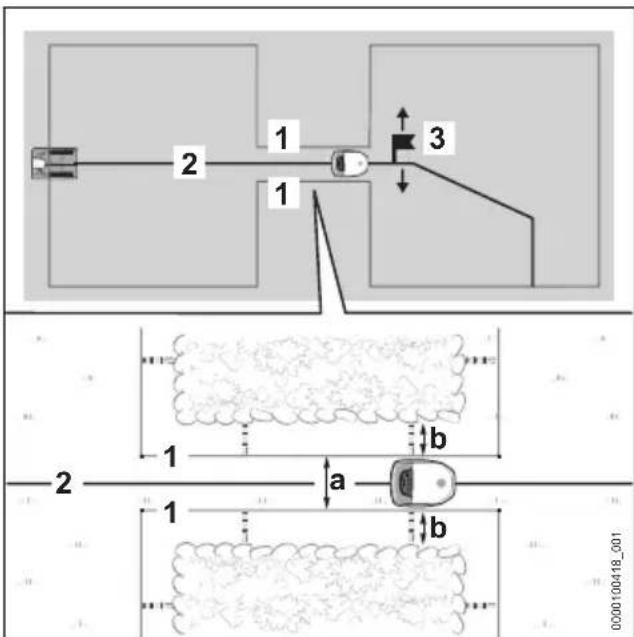
1 2 3 1 2 a b 1 b 0000100418_001A guide wire (2) directs the robot mower through the confined area, provided that a minimum width (a) is maintained between the perimeter wires (1).
On completing commissioning, it is mandatory to place a starting point (3) behind the confined section and the starting point's approach frequency. Otherwise, the robotic mower will not
8 Installing the Perimeter Wire English
find its way through the confined section. Starting points can be set using the MY iMOW® app.
- Route the perimeter wire (1) as illustrated and make sure that the following dimensions have been maintained:
- Minimum distance between the perimeter wires (1) in the confined section: a = 55 ~cm
- If the confined section is restricted by side obstacles: Include an additional distance of b = 37 cm (length: 1x iMOW® Ruler)
- Route the guide wire (2) in the middle of the confined section.
If the side distance b = 37 cm (length: 1x iMOW® Ruler) is not possible: Install a corridor to be able to guide the robot mower to another mowing area ☐8.11 or block off the confined section from the mowing area.
8.11 Corridor
Functional Description
flowchart
graph TD
    A["Block A"] -->|1| B["Block B"]
    A -->|2| A
    A -->|3| A
    B -->|00000100068_003| B
    style A fill:#f9f,stroke:#333
    style B fill:#bbf,stroke:#333
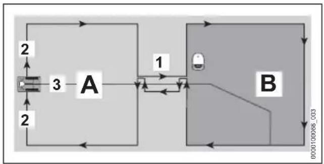
Use a corridor (1) to overcome confined sections in a precise way or to define passageways. The corridor divides the mowing area into a main mowing area (A) and another mowing area (B).
The perimeter wire (2) is routed without interruptions. It forms a corridor at the transition from the main mowing area (A) to the other mowing area (B).
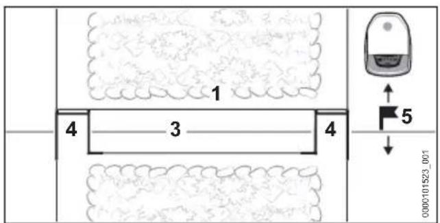
text_image
1 4 3 4 5 0000101523_001Wire loops (4) indicate to the robotic motor when a corridor starts or ends.
A guide wire (3) must be installed in the middle of the corridor.
A corridor must be followed by a starting point (5) within the mowing area (B). Otherwise, the robotic mower will not find its way from the main mowing area (A) through the corridor to the other mowing area (B). Starting points and their approach frequency can be set using the MY iMOW® app.
There is no mowing within a corridor.
General requirements
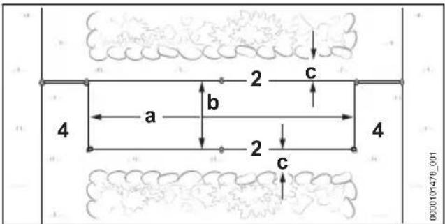
text_image
2 c a b 2 c 4 4 0000101478_001▶ Make sure that the following conditions are fulfilled:
- The minimum distance between the wire loops (4) must be at least a = 74 cm .
- The distance between the perimeter wires (2) must be at least b = 55 cm .
- The distance to side obstacles must be at least c = 15 cm.
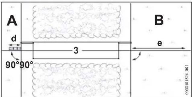
text_image
A d 90°90° 3 B e 0000101524_001▶ Make sure that the following conditions are fulfilled:
- The guide wire (3) can be routed before the corridor for a length of at least d = 37 cm (length: 1x iMOW® ruler) in a straight line and at a right angle ( 90^ ) to the corridor.
- The guide wire (3) can be routed after the corridor for a length of at least e = 2 m in a straight line and at a right angle ( 90^ ) from the corridor into the mowing area (B).
▶ If the distances and lengths cannot be complied with, the mowing area (B) must be separated from the main mowing area (A) and a side area must be installed.
Installing a corridor
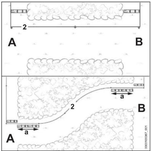
text_image
2 A B a 2 A B 0000100067_001▶ Guide the perimeter wire (2), as illustrated, from the main mowing area (A) to the mowing area (B).
If the corridor is to be installed in an arc: Route the perimeter wire (2) for a length of a = 74 cm (length: 2x iMOW® ruler) at the start and end of the corridor and at a right angle (90^) to the mowing area.
- Route the perimeter wire (2) clockwise around the mowing area (B) and back to the corridor.
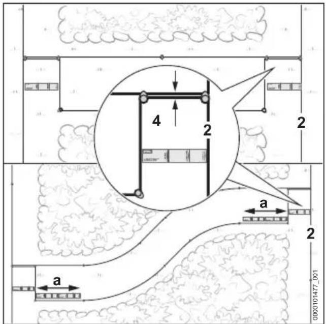
text_image
4 2 a a 0000101477_001- Route the perimeter wire (2) parallel and closely together for 37 cm (length: 1x iMOW® ruler) without the perimeter wires crossing over each other.
-
Route the perimeter wire (2) parallel at a distance of at least 55 cm toward the main mowing area (A).
-
Route the perimeter wire (2) parallel and closely together for 37 cm (length: 1x iMOW® ruler) to the main mowing area (A) without the perimeter wires crossing over each other.
If the corridor is to be installed in an arc: Route the perimeter wire (2) for a length of a = 74 cm (length: 2x iMOW® ruler) at the start and end of the corridor and at a right angle (90^) to the mowing area.
▶ Complete the routing of the wire on the main mowing area (A).
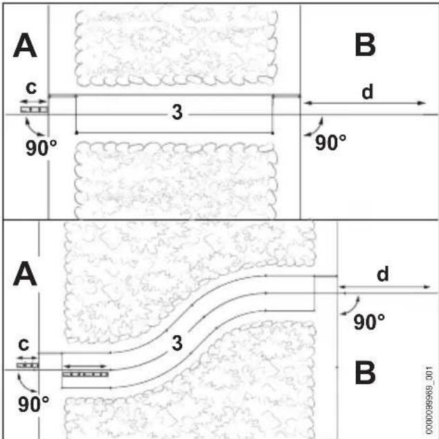
text_image
A c 90° 3 B d 90° A c 90° 3 B d 90° C000038968_001- Route the guide wire (3) on the main mowing area (A) for a length of at least c = 37 cm (length: 1x iMOW® ruler) in a straight line and at a right angle (90°) to the corridor.
- Route the guide wire in the center of the corridor.
▶ Route the guide wire (3) after the corridor for a length of at least d = 2 m in a straight line and at a right angle (90°) into the mowing area (B).
8.12 Inclines/slopes
The robot mower can navigate and mow inclines up to 45%. With the Upgrade Kit 10, iMOW ^® traction wheels gradients of up to 60 % can be driven and mowed. The Upgrade Kit 10 is available as a special accessory.
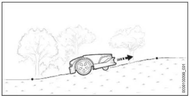
natural_image
Line drawing of a car on a dirt path with trees and an arrow indicating direction (no text or symbols)▶ If there is an incline/slope up to 27% within the mowing area: Install perimeter wire normally.
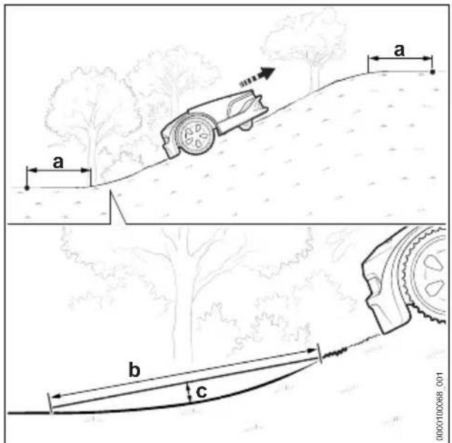
text_image
a b c 0000100068_001▶ If there is an incline/slope of more than 27% within the mowing area: Install the perimeter wire with a minimum distance a = 1.20 m before and after the incline/slope.
So that the robot mower can navigate the transition between level ground and the incline/slope, the radius of the transition must be such that for b = 1 m the distance to the ground c = 10 cm must not be exceeded.
8.13 Side Area
The robot mower cannot reach an adjacent area by itself. The customer must place the robot mower in the adjacent area.
A guide wire must not be installed in an adjacent area.
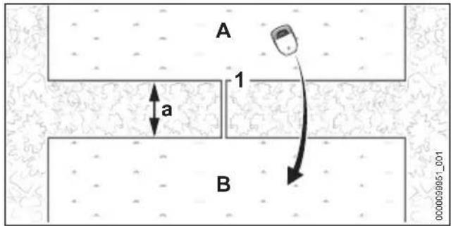
text_image
A 1 a B 0000039951_001- Route the perimeter wire (1) from the main area (A) to the adjacent area (B).
Minimum distance to the perimeter wires a = 74 cm
▶ Make sure that the length of the perimeter wire (1) does not exceed 850 m.
▶ Route the perimeter wires (1) in parallel and close to each other back to the mowing area (A) without the perimeter wires crossing.
8.14 Small Mowing Area
The STIHL AKM 100 small area module must be used for a small mowing area where less than 20 m of perimeter wire is required.
The STIHL AKM 100 stabilizes the wire signal and is incorporated into the perimeter wire by means of wire connectors.
9 Completing the Perimeter Wire Installation
9.1 Completing the routing of the perimeter wire
Docking station on the edge of the mowing area, docking station on the edge of the lawn area
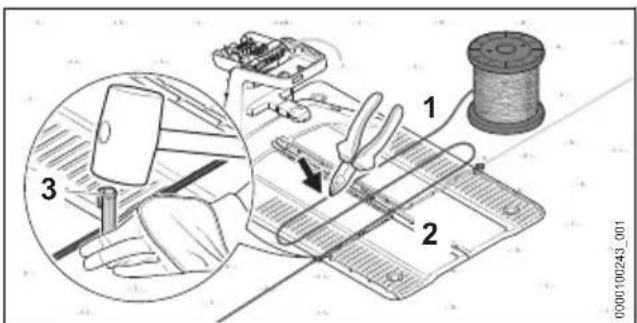
text_image
Technical diagram illustrating a sewing process with labeled parts and a magnified inset showing hand-cranking technique.- Attach the perimeter wire (1) directly on the base plate (2) with a fixing pin (3).
▶ Use the perimeter wire (1) to measure two times the width of the base plate (2) and then cut the perimeter wire (1) to length with a wire cutter.
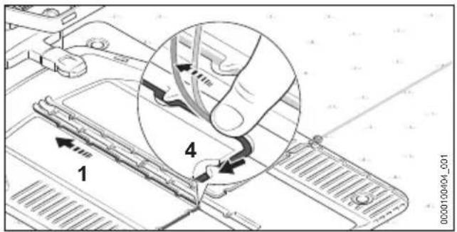
text_image
1 4 0000100404_001▶ Install the perimeter wire (1) in the base plate so that the guide wire lies flat in the cable duct and is secured by the hook (4).
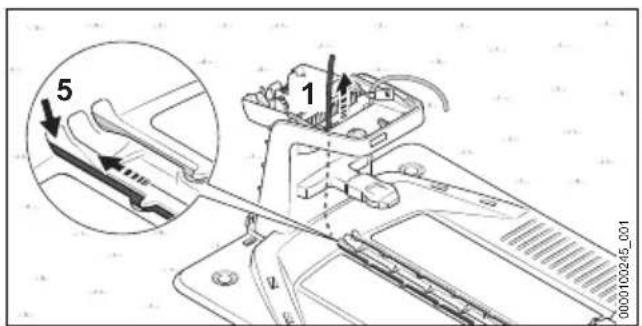
text_image
Technical diagram showing mechanical assembly with labeled parts and a magnified inset view of a component with arrows indicating motion or force.- Insert the perimeter wire (1) into the left conduit (5) and feed it through.
Push the wire end (1) upward inside the docking station.
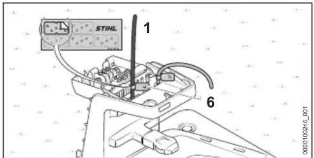
text_image
STIHL 1 6 0000100246_001▶ Mark the wire end (1) near the housing using the matching cable marker (6).
Docking station outside the mowing area
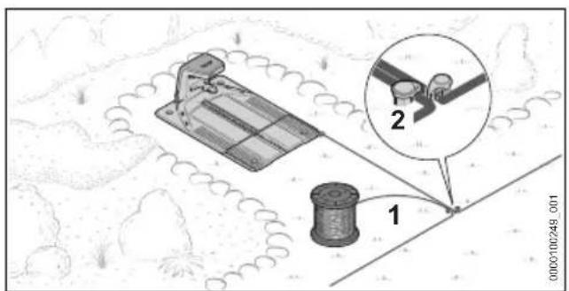
text_image
Diagram showing mechanical components and a magnified view of a component labeled '1' and '2', with a watermark at the bottom.▶ Route the perimeter wire (1) close to the already routed perimeter wire and secure with a fixing pin (2).
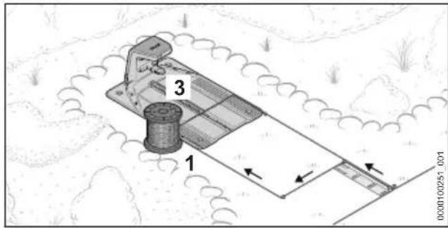
text_image
3 1 0000100251_001- Route the perimeter wire (1) parallel and closely to the other perimeter wire for 37 cm (length: 1x iMOW® Ruler) back to the docking station without crossing over the perimeter wires.
▶ Route the perimeter wire (1) back to the edge and further toward the base plate (3).
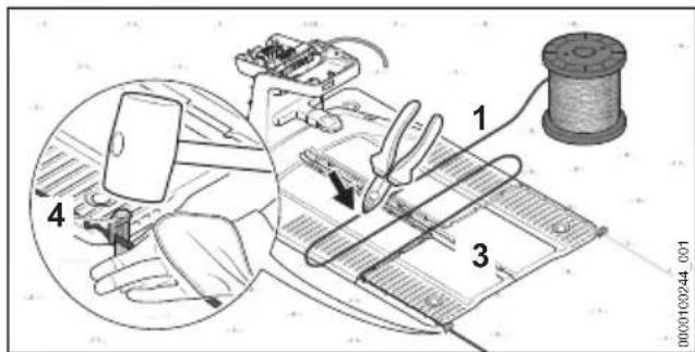
text_image
Diagram illustrating a mechanical or electrical procedure with labeled components including a tool, switch, and wire spool.▶ Attach the perimeter wire (1) directly on the base plate (3) with a fixing pin (4).
▶ Use the perimeter wire (1) to measure two times the width of the base plate (3) and then cut the perimeter wire (1) to length with a wire cutter.
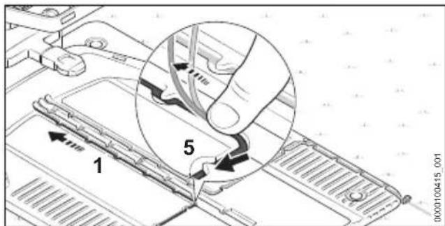
text_image
1 5 0000100445_001▶ Install the perimeter wire (1) in the base plate so that the guide wire lies flat in the cable duct and is secured by the hook (5).
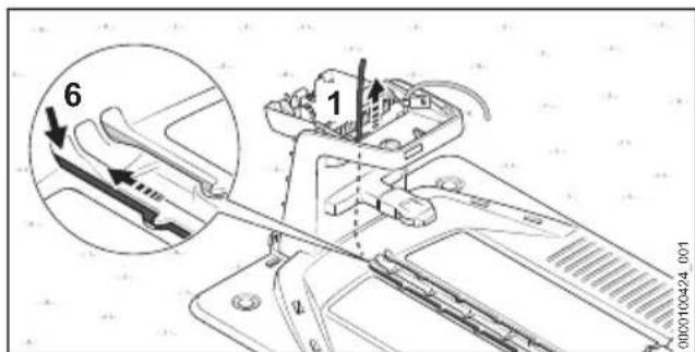
text_image
6 1 0000100424_0019 Completing the Perimeter Wire Installation English
▶ Insert the perimeter wire (1) into the left conduit (6) and feed it through.
Push the wire end (1) upward inside the docking station.
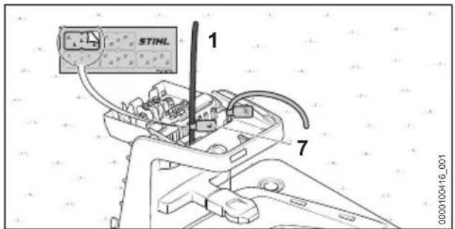
text_image
STINL 1 7 0000100416_001▶ Mark the wire end (1) near the housing using the matching cable marker (7).
It is mandatory to define a starting point within the mowing area at the conclusion of commissioning. Otherwise, the robotic mower will not find its way to the mowing area. Starting points and their approach frequency can be set using the MY iMOW® app.
Setting up the docking station in the center of the mowing area
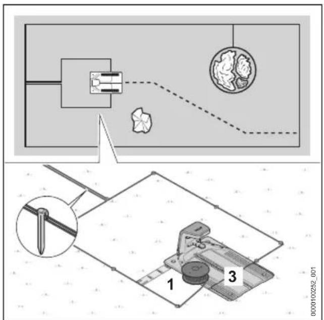
text_image
Technical diagram showing a mechanical assembly with labeled components and a close-up of a tool or device with parts numbered 1, 2, and 3.- Route the perimeter wire (1) close to the already routed perimeter wire.
- Route the perimeter wire (1) parallel and close to the other perimeter wire back to the docking station without crossing over the perimeter wires.
- Route the perimeter wire (1) toward the front around the base plate (3) at a distance of 37 cm (length: 1x iMOW® Ruler).
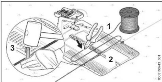
text_image
Technical diagram showing a sewing machine setup with labeled parts and a magnified view of the tool's cutting process.- Attach the perimeter wire (1) directly on the base plate (2) with a fixing pin (3).
▶ Use the perimeter wire (1) to measure two times the width of the base plate (2) and then cut the perimeter wire (1) to length with a wire cutter.
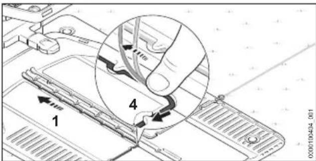
text_image
1 4 0300100404_001▶ Install the perimeter wire (1) in the base plate so that the guide wire lies flat in the cable duct and is secured by the hook (4).
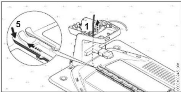
text_image
5 1 000100245 001- Insert the perimeter wire (1) into the left conduit (5) and feed it through.
Push the wire end (1) upward inside the docking station.
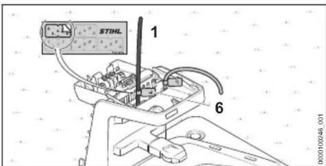
text_image
STINL 1 6 0000100246 001▶ Mark the wire end (1) near the housing using the matching cable marker (6).
10 Installing Guide Wire
10.1 Installing guide wire
Take into account the position of all guide wires when installing the perimeter wire.
▶ Take into account the general guidelines for installing the guide wire 8.2.

text_image
Technical diagram of a mechanical assembly with labeled parts and an inset showing a tool interacting with a component.- Insert the beginning of the guide wire (1) into the middle conduit (2) and feed the wire through. Push the guide wire (1) upward inside the docking station.
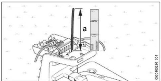
text_image
a 0000100296_001▶ Feed the guide wire (1) through until it protrudes upward for a = 37 cm (length: 1x iMOW® Ruler).
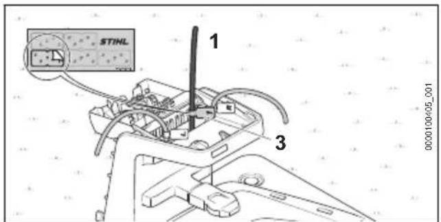
text_image
STIML 1 3 0000100-05_001▶ Using the appropriate cable marker (3), mark the guide wire (1) near the housing. Marking will facilitate the subsequent connection to the correct terminal.
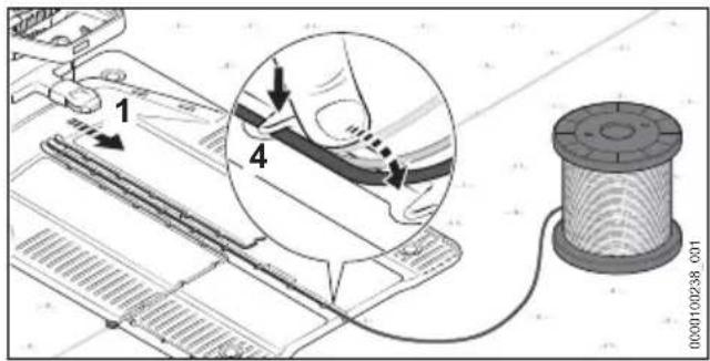
text_image
Technical diagram showing mechanical assembly with labeled parts and a spool, likely illustrating a cable or wire connection.▶ Install the guide wire (1) in the base plate so that the guide wire lies flat in the cable duct and is secured by the hook (4).
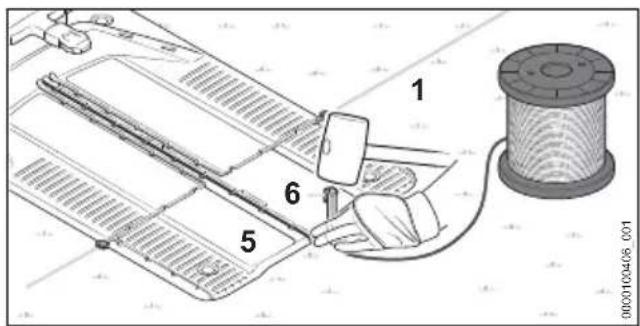
text_image
Technical diagram showing a mechanical assembly with numbered components and a spool, likely illustrating a gear or motor mechanism.- Attach the guide wire (1) directly at the base plate (5) with a fixing pin (6).
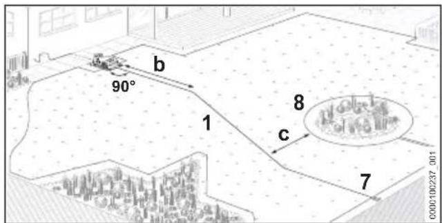
text_image
b 90° 1 8 c 7 0000100237_001- Route the guide wire (1) for b = 2 m in a straight line and at a right angle ( 90^ ) from the docking station to the mowing area. - Route the guide wire (1) to the wire loop (7) at the edge of the mowing area. The distance to circumferential perimeter wire (8) must be at least c = 27.5 cm .
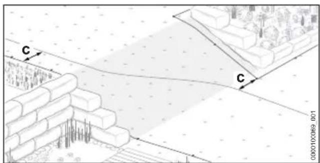
text_image
C C 0000100069 001- Route the guide wire diagonally on inclines. The distance to the perimeter wire must be at least c = 27.5 cm .
11 Electrically connecting the docking station English
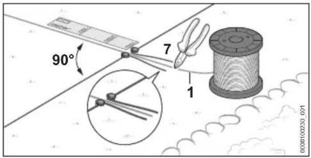
text_image
90° 7 1 0000100230.001▶ Route guide wire (1) for at least e = 37 cm (length: 1x iMOW® Ruler) in a straight line and at a right angle (90°) to the wire loop (7).
- Route the guide wire (1) through the center of the wire loop (7).
▶ Using a wire cutter, cut through the guide wire (1) at the end of the wire loop (7) and make all wire ends the same length.
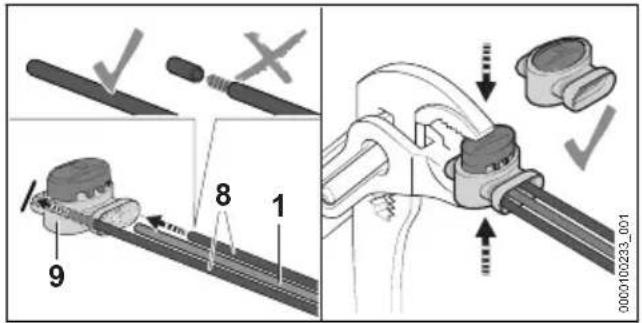
text_image
Technical diagram showing mechanical assembly steps with numbered components and checkmark indicators- Insert the ends of the perimeter wires (8) and the guide wire (1) into the wire connector (9) up to the limit stop. Do not strip the wire ends.
▶ Press the wire connector (1) together up to the limit stop with a pair of pliers.
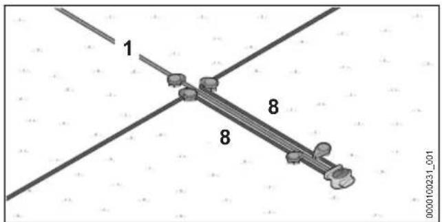
text_image
1 8 8 0000100231_001- Route the perimeter wires (8) and guide wire (1) in parallel and close to each other without the wires touching.
- Secure the wires using additional fixing pins.
11 Electrically connecting the docking station
11.1 Connecting perimeter wire and guide wire
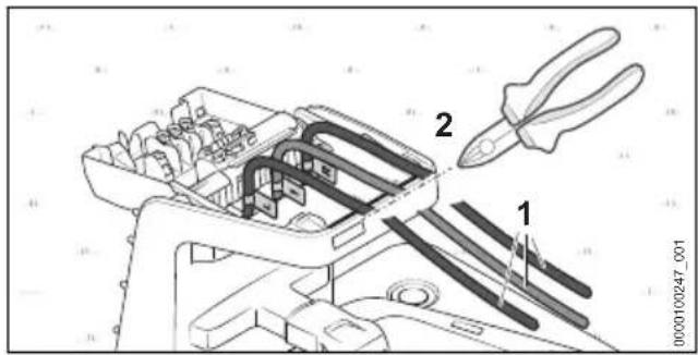
text_image
Technical diagram showing a tool being inserted into a mechanical component with labeled parts 1 and 2.▶ Slightly tension the wire ends (1) and cut to length along the edge (2) with a wire cutter.
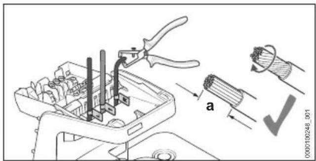
text_image
Technical diagram showing a pliers tool in a mechanical assembly with labeled parts and a checkmark indicating inspection.▶ Strip a = 10 mm of the wire ends.
- Twist wire strands so that no individual strands stick out.
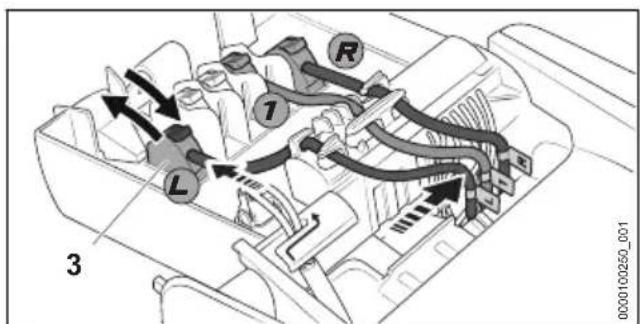
text_image
R 1 L 3 0000100250_001- Assign the labeled wire ends to the respective terminals.
▶ Fold the lever of the corresponding terminal (3) backward.
- Insert the insulated wire end into the corresponding terminal (3) and fold the lever forward again to close.
- Secure the perimeter wires and guide wire in the cable holders as shown and press toward the right.
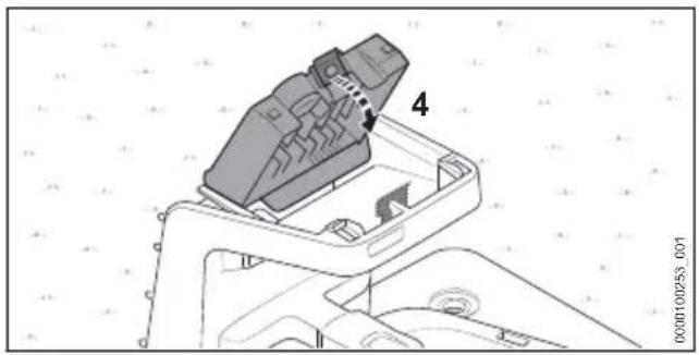
natural_image
Technical diagram of a mechanical component with numbered part (4), no readable text or symbols present▶ Fold the cover (4) toward the front. The cover (4) engages with an audible and noticeable click.
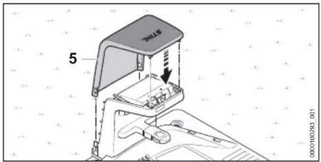
text_image
5 HILLS▶ Put on the hood (5). The hood (5) engages with an audible click.
11.2 Routing the charging cable and connecting the power supply
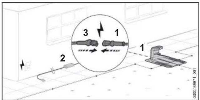
text_image
1 2 3 0000089971_001- Route the charging cable (1) to the location of the power supply (2).
▶ Choose the power supply (2) location so that the following conditions are met:
- The power supply (2) and the connecting cable are outside of the mowing area.
- A suitable wall socket is within reach of the power supply (2).
- The power supply (2) rests on a flat and not permanently wet surface.
- The power supply (2) is installed elevated above the ground in case it is exposed to more protracted wet conditions.
- If possible, protect the location against adverse weather conditions and direct sunlight.
- Route the charging cable so that the following conditions are met:
- The charging cable (1) is outside of the mowing area.
- The charging cable (1) is routed so that people cannot trip over it.
- The charging cable (1) is not under tension or tangled.
- The charging cable (1) is completely unwound and is not under the docking station.
- The charging cable (1) is not on a permanently wet surface.
- Connect charging cable (1) with the plug (3) of the power supply (2).
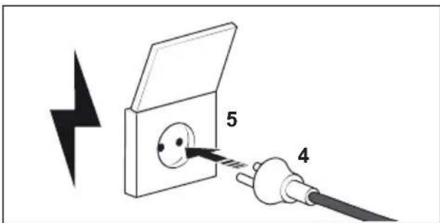
text_image
5 4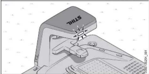
natural_image
Diagram of a computer mouse with a 'STILK' label, showing the handle and control panel (no readable text or symbols beyond label)▶ Plug the mains plug (4) into a correctly installed socket (5).
The LED on the docking station lights up green.
11.3 Mounting the power supply on a wall
The power supply can be mounted on a wall.
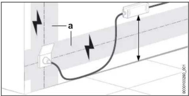
text_image
a 0000100290_00112 Charging the Robot Mower English
▶ Mount the power supply so that the following conditions are met:
- Suitable fixing materials.
- The power supply is level.
Following distances are complied with:
- The power supply is outside of the range (a) of possible electrical installations.
- A suitable socket is within reach of the power supply.
- If possible, protect the location against adverse weather conditions and direct sunlight.
12 Charging the Robot Mower
12.1 Charging the robotic mower
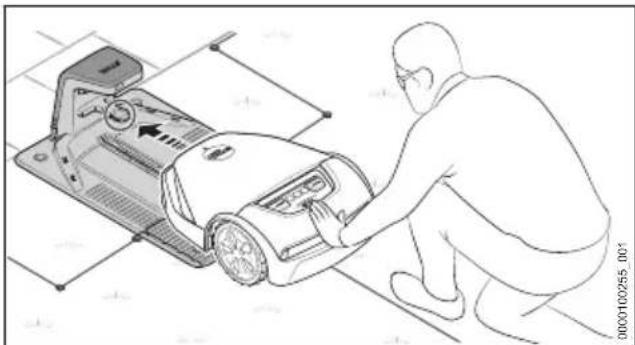
natural_image
Line drawing of a person using a robotic device to adjust or install a vehicle (no text or symbols visible)▶ Push the robot mower into the docking station up to the limit stop.
The robot mower carries out a system start and begins charging.
The charging time depends on various factors, e.g. the battery temperature or the ambient temperature. For optimum performance, note the recommended temperature ranges, 23.7.
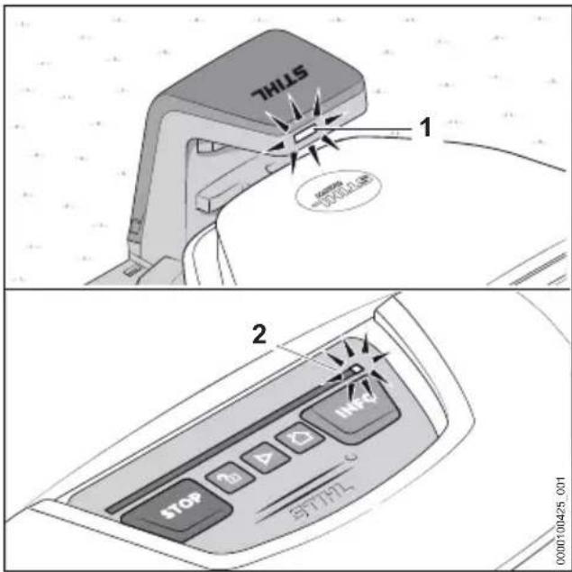
text_image
STHL 1 2 STOP 3D D INFA 3YT17L-001The LED (1) on the docking station lights up white. An LED (2) lights up white on the light strip of the robot mower.
After the first charging, the robotic mower will charge automatically in the future as soon as it returns to the docking station after a mowing job.
Energy efficient charging
In order to charge the robotic mower's battery with a minimum amount of energy, all of the robotic mower's and docking station's unnecessary extra features besides the charging function can be deactivated.
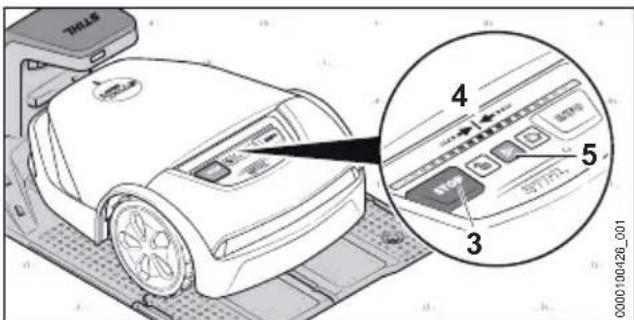
text_image
7THLS 4 5 3 000010026_001▶ If the theft protection function in the MY iMOW® app is activated, deactivate the theft protection.
Press the following key combination one after the other:
▶ Press STOP (3).
The robot mower is stopped and locked
▶ Press and hold STOP (3) until the light strip (4) fully lights up red.
▶ Press STOP (1).
The light strip (4) flashes twice. The device lock of the robot mower is activated.
▶ Press and hold STOP (3) until the light strip (4) fully lights up red and finally flashes red twice.
"Energy efficient charging" mode is activated.
The robot mower's battery is fully charged. All extra functions are deactivated.
After charging is complete, the robot mower must be activated so that it is operational again:
▶ Press START (5).
The robotic mower is operational.
13 Closing Bluetooth® Radio Interface
13.1 Setting up the Bluetooth ^® -radio interface
The robotic mower regularly emits a Bluetooth ^® signal in order to be able to connect with a
mobile device. In delivered condition, the radio interface is not password protected.
Download the MY iMOW® in the app store of your mobile device and create an account.
- Add the robotic mower to the account.
▶ Follow the instructions on the screen and secure the Bluetooth ^® radio interface with a password.
After the password is assigned, the mobile device is authorized to control and configure the robot mower.
An additional mobile device can only be authorized by entering the selected password. In this way, the robot mower is secured against unauthorized access.
14 Light patterns on the robot mower and charging station
14.1 Light strips on the robot mower
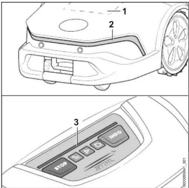
text_image
Technical diagram showing three views of a robotic device with labeled parts: front view, interior control panel, and rear view.The matrix display (1) and the light strips (2 and 3) indicate the robot mower's status and faults.
White light pattern:
- No active mowing.
Green light pattern:
- Mowing is active.
Blue light pattern:
- The robot mower is receiving a system update or the system is restarting.
Red light pattern:
– Device lock is active.
- Fault message.
14.2 LED on the docking station
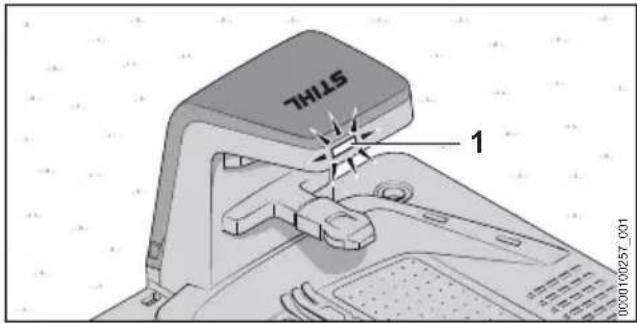
text_image
STILL 1The LED (1) indicates the docking station status and faults.
LED (1) lights up white:
- The docking station is operational.
- The robot mower is in the docking station without active mowing.
- The robot mower is charging without active mowing.
The LED (1) lights up green.
- The robot mower is being partially recharged during mowing.
LED (1) lights up red.
- There is a fault.
LED (1) lights up blue:
- Communication with the robot mower.
15 Operating and Adjusting the Robot Mower
15.1 Control Panel
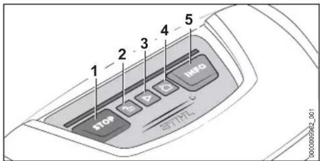
text_image
1 2 3 4 5 STOP B D INFO ST7H7L 0000099362_001Use the pushbuttons (1 to 5) to operate the robotic mower's basic functions. The full scope of functions is available in the MY iMOW® app.
Starting the Mowing Process
▶ Press START (3).
The robot mower starts mowing and later automatically returns to the docking station.
Stopping the mowing process and locking the robot mower
▶ Press STOP (1).
The robot mower and the mowing unit stop. The robot mower is locked.
Sending the robot mower to the docking station
▶ Press HOME (4).
The robot mower returns to the docking station.
Unlocking the robot mower
▶ Press LOCK (2).
▶ Press the displayed key combination.
Accessing information
▶ Press INFO (5).
The robotic mower reports audible information about the current status.
15.2 The MY iMOW®
The MY iMOW® app is required for the convenient use of the robotic mower. The robotic mower can be operated and configured via the MY iMOW® app. The robotic mower can be connected to a mobile device via a wireless network connection (WLAN) and mobile phone connection or Bluetooth®. The robotic mower can be operated and configured from a desktop computer using the MY iMOW® web app.
Main functions:
- Starting and stopping the mowing process
-
Mowing plan
-
Configuring mowing times (with an assistant or manually)
-
Configuring starting points (optional)
– Selecting zones (optional) -
Setting the cutting height
- Remote access to the robotic mower via a wireless network connection (WLAN)
- Remote access to the robotic mower via a mobile phone connection.
- Support
16 Stopping the robot mower and activating the device lock
16.1 Stopping the robot mower and activating the device lock


WARNING
■ The robot mower may unintentionally be switched on if the robot mower is not stopped and shut down by activating the device lock as described in this User Manual. This may result in serious injury to people and damage to property.
- Stop the robot mower and activate the device lock during transport, storage, cleaning, servicing and repair or when there is changed or unusual behavior.
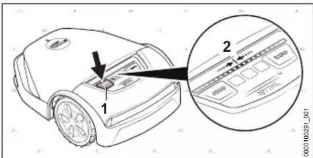
text_image
Diagram of a robotic device with labeled parts and an inset showing internal control panel layout▶ Press STOP (1).
The robot mower is stopped and locked.
▶ Press and hold STOP (1) until the light strip (2) fully lights up red.
▶ Press STOP (1).
The light strip (2) flashes twice. The device lock of the robot mower is activated. The robot mower can be transported, stored, cleaned or serviced.
17 Transporting
17.1 Transporting the robot mower
- Stop the robot mower and activate the device lock.
Carrying the robot mower
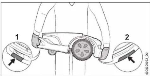
text_image
1 2 0000000003_001▶ Wear work gloves made of robust material.
- Carry the robot mower at the front grip surface (1) and the rear grip surface (2).
Transporting the robot mower in a vehicle
- Secure the robot mower so that it does not tip over and cannot move.
17.2 Transporting the Battery
The battery has been installed in the robot mower and must only be removed by a STIHL authorized dealer.
▶ Check that the battery is in a safe condition.
- Pack the battery in packaging in such a way that it cannot move inside the packaging.
- Secure the packaging so that it cannot move.
The battery is subject to the Carriage of Dangerous Goods regulations. The battery is classified as UN 3480 (lithium ion batteries) and has been tested pursuant to UN Manual Tests and Criteria Part III, Subsection 38.3.
The transport regulations can be found at www.stihl.com/safety-data-sheets.
18 Storing
18.1 Preparing the robotic mower for storage
STIHL recommends when the robotic mower is not used for longer periods of time, e.g., winter break, to put it into "hibernation". Hibernation deactivates all unnecessary extra functions of the robotic mower and ensures a low discharge of the battery.
▶ If the theft protection function in the MY iMOW ^® app is activated, deactivate the theft protection.
If the robotic mower's state of charge is below 50%: charge the robotic mower until its state of charge exceeds 50%.
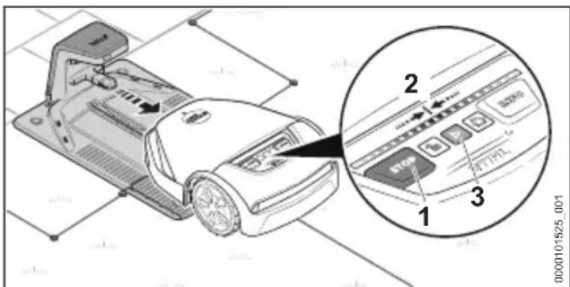
text_image
Diagram of a device with labeled parts and an inset showing a control panel with buttons and indicators.- Remove the robotic mower from the docking station.
Press the following key combination one after the other:
▶ Press STOP (1).
The robot mower is stopped and locked.
▶ Press and hold STOP (1) until the light strip (2) fully lights up red.
▶ Press STOP (1).
The light strip (2) flashes twice. The device lock of the robot mower is activated.
- Press and hold STOP (1) until the light strip (2) fully lights up red and finally flashes red twice.
The hibernation mode is activated. All extra functions are deactivated.
After the winter break, the robot mower must be activated so that it is operational again:
▶ Move robot mower to the mowing area.
▶ Press START (3).
The "hibernation" mode is deactivated and the robotic mower is once again operational.
18.2 Storing the robotic mower
- Store the robotic mower so that the following conditions have been met:
- The robot mower is out of the reach of children.
- The robotic mower is clean and dry.
- The robotic mower is in an enclosed space.
– The robotic mower's battery is charged. - Do not store the robotic mower outside of the specified temperature limits, 23.6.
- The robotic mower cannot tip over.
- The robotic mower cannot roll away.
- The robot mower is horizontal on its wheels.
- No objects are placed on the robot mower.
The robot mower can also be stored on a wall holder. The wall holder is available as an accessory.
NOTICE
■ If the robotic mower is not stored as described in this User Manual, the battery may become deeply discharged and irreparably damaged.
- Charge the battery of the robotic mower before storage.
18.3 Storing the docking station, charging cable and power supply
During longer periods of non-use, e.g. in winter, the docking station, charging cable and power supply may remain in the mowing area.
- Disconnect the power supply's mains plug from the wall socket.
- Protect the mains plug against weather conditions.
▶ Clean all components.
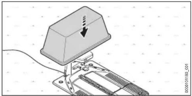
natural_image
Mechanical device with a highlighted component and arrow indicator (no text or symbols)▶ Cover the docking station, e.g., with a large pail or a mortar bucket.
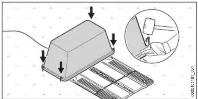
text_image
Diagram showing a device with arrows indicating force application, alongside an inset image of a hand pressing a component.- Secure the pail or mortar bucket to the ground with pegs.
Dismantling the docking station, charging cable and power supply
To store the wall holder available as an accessory, or if covering is not possible, the docking station, charging cable and power supply can also be removed.
- Disconnect the power supply's mains plug from the wall socket.
▶ Clean all components. - Disconnect the charging cable from the docking station and power supply and coil it.
- Remove power supply and coil up connecting cable.
- Disconnect perimeter wire and guide wire from the docking station.
▶ Grease wire ends to protect against corrosion and weather conditions.
▶ Remove the docking station.
19 Cleaning
19.1 Cleaning the Robot Mower

WARNING
■ The cutting edges of the blades are sharp. There is a risk of cutting oneself.
▶ Wear work gloves made of robust material.
- Stop the robot mower and activate the device lock.
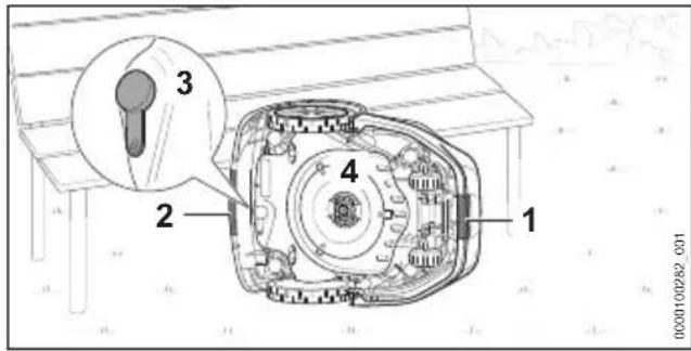
text_image
1 2 3 4 0000100282 001▶ Grip the robotic mower at the front grip surface (1) and the rear grip surface (2).
▶ Place the robot mower on its side and secure it against falling over.
▶ Check the plug (3) of the diagnostic socket for damage and tight fit.
▶ If the blade disk (4) is heavily soiled, remove the blade disk (4).
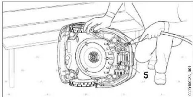
natural_image
Technical line drawing of a mechanical assembly with hands and a numbered component (no readable text or symbols)▶ Remove the dirt with a wooden rod or a soft brush. If necessary, use a ph-neutral detergent. STIHL recommends STIHL Multiclean.
- Rinse off loose dirt with a gentle water jet.
- Clean the underside of the robotic mower with a damp cloth.
▶ Clean the charging contacts (5) with a damp cloth.
- Clean the hood and control panel with a damp cloth.
19.2 Cleaning the docking station, power supply, charging cable and plug connections
- Disconnect the power supply's mains plug from the wall outlet.
- Clean the docking station, power supply and charging cable with a damp cloth.
▶ If necessary, remove built-up dirt with a soft brush. - Clean plug connections with a dry lint-free cloth.
▶ If necessary, remove built-up dirt with a brush.
20 Maintenance
20.1 Visual Inspection
▶ Regularly check the robot mower:
– Cleanliness of the charging contacts
- Check the hood and protective strip for damage
- Check that the wheels run smoothly
- Check the blades for damage, wear, cracks and smooth running
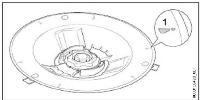
natural_image
Technical line drawing of a mechanical component with a circular housing and internal components, no visible text or symbols.- Check the blade disk for damage and wear.
- If the wear marks (1) are worn through, creating a hole, replace the blade disk.
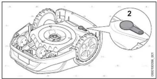
natural_image
Technical line drawing of a robotic lawn mower with labeled component '2' (no text or symbols beyond label)- Check the plug (2) of the diagnostic socket for damage and tight fit.
20.2 Replacing blades

WARNING
■ The cutting edges of the blades are sharp. There is a risk of cutting oneself.
▶ Wear work gloves made of robust material.
- Stop the robot mower and activate the device lock.
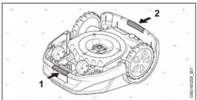
text_image
Technical diagram of a robotic arm with labeled parts 1 and 2, showing internal gears and housing structure.▶ Grab the robot mower at the front grip surface (1) and the rear grip surface (2).
▶ Turn the robot mower on its back.
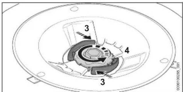
text_image
3 4 3 0000100285_001▶ Press and hold the lever (3).
▶ Rotate the nut (4) counterclockwise until it can be removed.
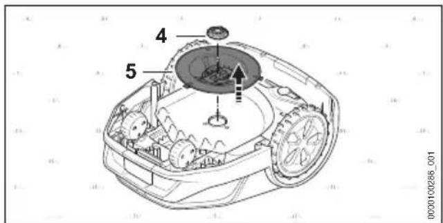
text_image
4 5 0000100286_001▶ Push the blade carrier (6) in the direction indicated by the arrow ♂
The blade carrier (6) is unlocked.
▶ Remove the blade carrier (6).
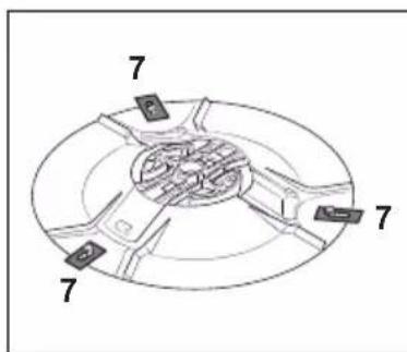
text_image
7 7 7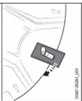
text_image
Diagram showing a car interior with directional arrows and vehicle labels, likely indicating movement or navigation.▶ Detach all old blades (7).
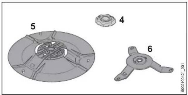
natural_image
Technical illustration of a mechanical component with numbered parts (no text or symbols)▶ Clean, blade disk (5), blade carrier (6) and nut (4).
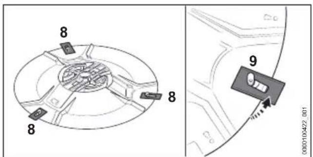
text_image
8 8 8 9 0000100422_001- Attach new blades (8). Insert only one blade per pin (9).
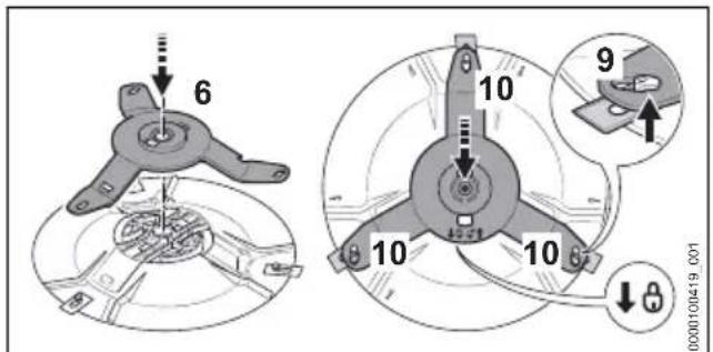
text_image
6 10 9 10 10 000100419_001▶ Put on the blade carrier (6).
▶ Push the blade carrier (6) in the direction of the arrow and make sure that all three arms (10) underneath the pins (9) are positioned.
The blade carrier (6) is locked.
▶ Position the blade disk (5) on the robot mower.
▶ Press and hold the lever (3).
▶ Turn the nut (4) clockwise.
▶ Release the lever (3) and tighten nut (4) securely clockwise.
The levers (3) engage audibly.
21 Repairing
21.1 Repairing the robot mower, battery, blades, docking station and power supply
Users cannot repair the robot mower, battery, docking station and power supply themselves.
Damaged or worn blades can be replaced.
▶ If the robot mower, battery, docking station, charging cable, power supply or connecting cable is damaged: Do not use the robot mower, battery, docking station, charging cable, power supply or connecting cable and contact a STIHL authorized dealer.
▶ If a blade is damaged or worn:
- Stop the robot mower and activate the device lock.
- Replace all blades. The blades cannot be re-sharpened.
▶ If warning labels are illegible or damaged: Have the warning labels replaced by a STIHL authorized dealer.
21.2 Extending or repairing perimeter wire or guide wire
The perimeter wire or guide wire can be extended or repaired using wire connectors.
Wire connectors are filled with gel to prevent premature wear or corrosion of the wire ends.
▶ Make sure that the overall length of the perimeter wires does not exceed the maximum length of 850 m.
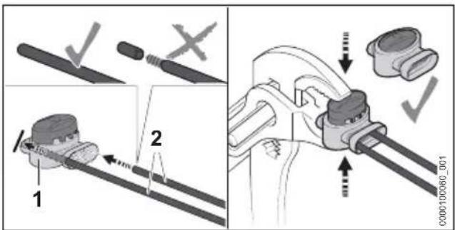
text_image
Technical diagram showing mechanical assembly steps with labeled components and checkmark indicators- Insert the wire ends (2) into the wire connectors (1).
Do not strip the wire ends.
▶ Press the wire connector (1) together up to the limit stop with a pair of pliers.
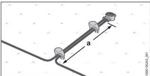
text_image
a 0000100242_001▶ Route perimeter wires at least for a length of a = 5 cm parallel and close together without the perimeter wires crossing over each other.
22 Troubleshooting
22.1 Troubleshooting the robotic mower
Most faults are indicated in the MY iMOW ^® app and by red light patterns on the robotic mower or docking station.
Proceed as follows for troubleshooting:
▶ Follow the instructions in the MY iMOW ^® app.
or
- Press the INFO pushbutton on the control panel and follow the audible instructions.
| Fault Light strips on the robot mower or docking station | on | Cause Remedy | |
| The robot mower stops on the way back to the docking station. | The battery is discharged. | Make sure that the length of the perimeter wire does not exceed 850 m.Optimize routing of the guide wire.Install another guide wire within the mowing area.Carry the robot mower to the docking station for charging.If possible, in a mowing area with a slope, position the docking station in the lower area of the slope. | |
| The robot mower fails to start the mowing process as expected. | Illuminated strips light up blue. | The robot mower is restarting. | Wait until the restart has been completed.The robot mower then automatically starts the mowing process. |
| Light strips light up red.The LED on the docking station lights up red. | There is a fault on the perimeter wire or guide wire. | Make sure that the perimeter wire or guide wire is undamaged.Make sure that the perimeter wire or guide wire is correctly connected to the docking station.Make sure that the perimeter wire and guide wire are correctly connected to the wire connector.Follow the instructions in the MY iMOW®app. | |
| The robotic mower is not charging. | Light strips light up red.The LED on the docking station lights up red. | There is a fault in the robot mower, battery, power supply or docking station. | Make sure that the charging contacts on the docking station and robotic mower are clean.Follow the instructions in the MY iMOW®app.If the fault persists: Do not attempt to further charge the robotic mower, remove the mains plug of the connecting cable from the socket outlet and contact a STIHL authorized dealer. |
23 Specifications
23.1 STIHL iMOW® 5.0 EVO, 6.0 EVO, 7.0 EVO Robotic Mower
Specifications
– Cutting width: 28 cm
– Cutting height - electric: 20 mm to 60 mm
– Speed of the blade disk: 2400 rpm
- Mowing speed
- iMOW® 5.0 EVO: 0.5 m/s
- iMOW® 6.0 EVO: 0.5 m/s
- iMOW® 7.0 EVO: 0.5 m/s
- Dimensions:
- Height: 291 mm
- Width: 525 mm
- Length: 705 mm
- Weight:
23 Specifications English
- iMOW ^® 5.0 EVO: 15 kg
- iMOW® 6.0 EVO: 15 kg
- iMOW® 7.0 EVO: 16 kg
- Protection class: III
– Degree of protection: IP56
– Maximum mowing area: - iMOW® 5.0 EVO: 1500 m²
- iMOW® 6.0 EVO: 3000 m²
- iMOW® 7.0 EVO: 5000 m²
- Active time 1000m^2 (per week)
- iMOW ^® 5.0 EVO: 35 h
- iMOW® 6.0 EVO: 30 h
- iMOW® 7.0 EVO: 20 h
– Maximum length of the perimeter wire: 850 m
– Maximum gradient: 45%
Bluetooth®
- Data connection: Bluetooth® 5.1. The mobile device must be compatible with Bluetooth® Low Energy 5.0 and support Generic Access Profile (GAP).
– Frequency band: ISM band 2.4 GHz
– Maximum RF power transmitted: 1 mW - Signal range: approx. 10 m. The signal strength depends on the ambient conditions and the mobile device. The signal range can vary greatly depending on local conditions and the receiver used. The range may be perceptibly reduced inside enclosed rooms and through metal barriers (such as walls, shelves or cases).
- Requirements for the operating system of the mobile device: See info.myimow.stihl.com
Radio network (WLAN)
– Network standard: IEEE 802.11b/g/n
– Frequency band: 2.4 GHz
– Maximum RF power transmitted: 100 mW
Mobile phone connection
- Format of the SIM card: eSIM
- Frequency bands
– LTE-Cat-M1: B1, B2, B3, B4, B5, B8, B12, B13, B20, B28, B66
- UMTS, HSDPA, HSPA+: B1, B2, B4, B5, B6, B8, B19
– GSM, GPRS, EDGE: 850 MHz, 900 MHz, 1800 MHz, 1900 MHz
– Radiated maximum transmission power: 2 W
– Average data volume per month: see FAQs at https://support.stihl.com
23.2 Blades
– Number of blades: 3
23.3 STIHL AAI battery
The battery has been installed in the robot mower and must only be removed by a STIHL authorized dealer.
– Battery technology: lithium-ion
- Voltage: 36 V
– Capacity in Ah: see rating label
– Energy content in Wh: see rating label
– Weight in kg: see rating label
23.4 Docking station and power supply
Docking station
- Protection class: III
– Degree of protection: IPX5
- Weight: 4.0 kg
- Perimeter wire and guide wire
– Voltage: 42 V DC
– Frequency range: 1.4 kHz to 20 kHz
Power supply
– Market-dependent versions:
- DM160E-420A
- DM160E-420AS
- DM160K-420A
- DM160S-420A
- DM210E-420A
- DM210E-420AS
- DM210K-420A
- DM210S-420A
- Weight:
- Version 160 W: 1.6 kg
- Version 210 W: 2.0 kg
– Rated voltage: See rating plate
– Frequency: see rating plate
– Rated power: see rating plate
– Charging current: See rating plate
– Protection class: II
– Degree of protection: IP 67
23.5 Extension Cords
If an extension cord is used, the cross sectional area of its conductors must meet the following minimum requirements – depending on the line voltage and length of the extension cord:
If rated voltage on the rating label is 220V to 240V:
- Cord length up to 20 m: AWG 15 / 1.5 mm ^2
English 24 Spare Parts and Accessories
- Cord length 20 m up to 50 m: AWG 13 / 2.5 mm ^2
If rated voltage on the rating label is 100V to 127V:
– Cord length up to 10 m: AWG 14 / 2.0 mm ^4
- Cord length 10 m up to 30 m: AWG 12 / 3.5 mm ^2
23.6 Temperature limits

WARNING
■ The battery in the robot mower is not protected against all environmental conditions. If the battery is exposed to certain environmental conditions, it may catch fire or explode. This may result in serious injury to people and damage to property.
- Do not charge the battery below 5°C or above 40°C.
- Do not use the robot mower below 5°C or above 40°C.
- Do not use the docking station and power supply below 5°C or above 40°C.
- Do not store the robot mower below 0°C or above 40°C.
- Do not store the docking station and power supply below - 20°C or above 60°C.
23.7 Recommended temperature ranges
For optimum performance of the battery installed in the robot mower and of the docking station and power supply, observe the following temperature ranges:
- Charging: 5°C to 40°C
- Use: 5°C to 40°C
– Storage of robot mower: 0°C to 40°C - Storage of docking station and power supply: - 20°C to 60°C
If the battery is charged, used or stored outside the recommended temperature ranges, performance may be reduced.
23.8 Noise values
The K value for the sound power level is 2 dB(A).
– Sound power level measured according to 2000/14 EC: 59 dB(A).
– Sound power level guaranteed according to 2000/14 EC: 61 dB(A).
23.9 REACH
REACH is an EC regulation and stands for the Registration, Evaluation, Authorisation and Restriction of Chemical substances.
For information on compliance with the REACH regulation see www.stihl.com/reach.
24 Spare Parts and Accessories
24.1 Spare parts and accessories
STIHL These symbols indicate original STIHL spare parts and original STIHL accessories.
STIHL recommends the use of original STIHL spare parts and accessories.
Despite ongoing market observation, STIHL is unable to judge the reliability, safety and suitability of other manufacturers' spare parts and accessories; accordingly, STIHL cannot warrant for the use of those parts.
Original STIHL spare parts and original STIHL accessories are available from STIHL dealers.
25 Disposal
25.1 Disposal of the robot mower
Contact local authorities or a STIHL authorized dealer for information on disposal.
Improper disposal can be harmful to health and pollute the environment.
The robot mower contains a built-in rechargeable battery, which must be disposed of separately.
- Return the robot mower to a STIHL authorized dealer for disposal.
The STIHL authorized dealer will remove the built-in battery from the robot mower for separate disposal.
▶ Take STIHL products including packaging to a suitable collection point for recycling in accordance with local regulations.
▶ Do not dispose with domestic waste.
26 EC Declaration of Conformity
26.1 STIHL iMOW ^® 5.0 EVO, 6.0 EVO, 7.0 EVO Robotic Mower
declares under our sole responsibility that Designation: Robotic mower
- Manufacturer's brand: STIHL
- Type: iMOW® 5.0 EVO, 6.0 EVO, 7.0 EVO
- Serial number: IA01
Designation: Docking station
– Manufacturer's brand: STIHL - Type: Docking station
- Serial number: IA01
conforms to the specifications of the Directives 2006/42/EC, 2011/65/EU, 2006/66/EC, 2014/53/EU and has been developed and built in compliance with the versions of the following standards valid at the production date: EN 50636-2-107, EN 60335-1 Ed 5, EN 55014-1, EN 55014-2, EN 61000-3-2, EN 61000-3-3, EN 62311, ETSI EN 301 489-1 V2.2.3 (2019-11), ETSI EN 301 489-3 V 2.1.2 (2021-03), ETSI EN 303 447 V1.3.1 (2022-07), ETSI EN 301 489-52 V1.2.1 (2021-11), ETSI EN 301 511 V12.5.1 (2017-03), ETSI EN 303 413 V1.2.1 (2021-04), ETSI EN 301 489-17 V3.2.4 (2020-09), ETSI EN 301 489-19 V2.2.1 (2022-09), ETSI EN 300 328 V2.2.2 (2019-07), ETSI EN 301 908-1 V13.1.1 (2019-11), ETSI EN 301 908-13 V13.1.1 (2019-11).
Participating notified body: VDE Prüf- u. Zertifizierungsinstitut GmbH, No. 0366, has verified the conformity in accordance with Annex III Module B of the Directive 2014/53/EU and has issued the following EU type examination certificate: 40055521.
The technical documents are stored at ANDREAS STIHL AG & Co. KG Product Approval.
The year of construction, the country of manufacture and the machine number are shown on the robotic mower.
Waiblingen, 2023-02-16
Robert Olma, Vice President, Regulatory Affairs & Global Governmental Relations
27 UKCA Declaration of Conformity
27.1 STIHL iMOW® 5.0 EVO, 6.0 EVO, 7.0 EVO Robotic Mower

declares under our sole responsibility that
Designation: Robotic mower
– Manufacturer's brand: STIHL
- Type: iMOW® 5.0 EVO, 6.0 EVO, 7.0 EVO
- Serial number: IA01
Designation: Docking station
- Manufacturer's brand: STIHL
– Type: Docking station
- Serial number: IA01
conforms to the specifications of the UK regulations The Restriction of the Use of Certain Hazardous Substances in Electrical and Electronic Equipment Regulations 2012, Supply of Machinery (Safety) Regulations 2008, Electromagnetic Compatibility Regulations 2016 and has been developed and built in compliance with the versions of the following standards valid at the production date: EN 50636-2-107, EN 60335-1 Ed 5, EN 55014-1, EN 55014-2, EN 61000-3-2, EN 61000-3-3, EN 62311, ETSI EN 301 489-1 V2.2.3 (2019-11), ETSI EN 301 489-3 V 2.1.2 (2021-03), ETSI EN 303 447 V1.3.1 (2022-07), ETSI EN 301 489-52 V1.2.1 (2021-11), ETSI EN 301 511 V12.5.1 (2017-03), ETSI EN 303 413 V1.2.1 (2021-04), ETSI EN 301 489-17 V3.2.4 (2020-09), ETSI EN 301 489-19 V2.2.1 (2022-09), ETSI EN 300 328 V2.2.2 (2019-07), ETSI EN 301 908-1 V13.1.1 (2019-11), ETSI EN 301 908-13 V13.1.1 (2019-11).
The technical documents are stored at ANDREAS STIHL AG & Co. KG.
The year of construction, the country of manufacture and the machine number are shown on the robotic mower.
Waiblingen, 2023-02-16
Robert Olma, Vice President, Regulatory Affairs & Global Governmental Relations
28 Open Source Software
28.1 Open source software
This product contains copyright protected open source software that has been published by the respective copyright holders under certain license terms such as GNU General Public License (GPL), GNU Lesser General Public License (LGPL), Apache License or similar licenses. If copyright protected notes, terms of use or license terms are contained in this User Manual that contradict the terms of an applicable open source license, they are not used in the User Manual. The use and dissemination of the contained open source software is subject exclusively to the respective open source license. Insofar as the applicable license grants you the right to the source code of this software and/or other additional data, you can obtain the source code from us during a period of three years after our last delivery of the product and if the license terms require it for as long as we offer customer support for the product. To obtain the complete corresponding source code from us, you can send your request with information of the product name, serial number and version of the corresponding software to the following address: ANDREAS STIHL AG & Co. KG, Open Source Team/Officer, Postfach 17 71, 71307 Waiblingen, Germany. We reserve the right to charge you the costs of the data carrier as well as shipping costs. You can find additional information at the following website: https://open-source.stihl.com
Table des matières
2.1 Documents applicables
text_image
9 8 7 10 000009822_0017 Poignée arrière
text_image
1 2 3 4 5 6 STOP INFO STIRL 7 000099355_0011 Bandeau lumineux
text_image
Labeled diagram of a device with numbered components and a magnified inset showing internal structure1 Fiche secteur
natural_image
Technical illustration showing a row of five identical metal tools and a mechanical device with pins (no text or symbols present)12 Baïonnette
text_image
6 7 8 9000100413_001text_image
Illustration showing various objects including a soccer ball, a cross, a bucket, and a broken structure with dimension 'a'natural_image
Line drawing of a robotic lawn mower on a road with grassy background (no text or symbols)text_image
a 000009825_001natural_image
Simple line drawing of a tool with a checkmark indicating selection (no text or symbols)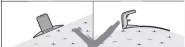
natural_image
Two abstract geometric shapes: a gray tower-like shape and a curved bracket, both on a textured surface (no text or symbols)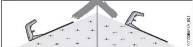
natural_image
Diagram showing two tool holders with a pointed tip and a triangular load, no text or symbols presenttext_image
Diagram showing a device connected to a wall-mounted panel, with an inset close-up highlighting the component's direction and movement.natural_image
Technical illustration of a mechanical device with a magnified inset showing a close-up view (no text or symbols)text_image
1 000009854_001text_image
Technical diagram of a mechanical assembly with numbered components and directional arrows indicating motion or movement.natural_image
Technical diagram of a mechanical assembly with arrows indicating motion or force direction (no text or symbols present)text_image
Technical diagram of a mechanical component with numbered parts and directional arrows indicating assembly or flow.natural_image
Technical illustration of a mechanical device with pins and a separate view showing a pin arrangement (no text or symbols)text_image
a 000009859_001text_image
Technical diagram showing mechanical assembly with labeled parts and a magnified inset highlighting a component detail.text_image
Technical diagram showing a vehicle interior with labeled parts 1, 3, and 4, including a magnified inset view of the component.text_image
Diagram showing a mechanical device with labeled parts and a spool, likely illustrating a cable or cable connection.text_image
Diagram of a mechanical device with labeled parts and a wire spool, showing components 1 and 3 on a grid background.text_image
Diagram of a mechanical device with labeled parts and connection point, showing motion path and cable specificationtext_image
Technical diagram showing a cable connection with labeled parts and a magnified detail view of the cable being inserted.text_image
Technical diagram showing a mechanical assembly with numbered components and an inset magnified view of a hand holding a device.text_image
Technical diagram showing mechanical assembly with labeled parts and a magnified detail view of a componenttext_image
Technical diagram showing a mechanical assembly with numbered components and a magnified inset view labeled 4text_image
Technical diagram showing a mechanical assembly with labeled components and directional arrows, including parts 1 and 3.text_image
a 000010058_001text_image
Diagram showing a vehicle with a road, a brain icon, a skull, and a cross symbol, possibly representing a road or navigation system.text_image
Diagram illustrating a mechanical or optical setup with labeled components and a magnified view of the process.8.4 Surface praticable
natural_image
Line drawing of a robotic car on a paved surface next to a brick wall (no text or symbols)text_image
a 0000100062_001text_image
0000100063_001 atext_image
a a 1 b 0000100055_001text_image
Diagram illustrating a mechanical or structural process with labeled components and directional arrows, including symbols like 'X' and directional arrows.natural_image
Line drawing of a robotic vacuum cleaner next to a rubber dome, with no text or symbols present.natural_image
Line drawing of a car driving on a dirt path with trees in the background (no text or symbols)text_image
Technical diagram illustrating a sewing or sewing process with labeled components and a magnified view of the tool's cutting tool.text_image
5 1 000010245_001text_image
Diagram illustrating a mechanical or agricultural setup with labeled components and a magnified inset showing component 2.text_image
3 1 0000:00254_001text_image
Technical diagram illustrating a sewing process with labeled parts including a sewing machine, spool, and fabric strips.text_image
1 5 0000100415_001text_image
Technical diagram showing a mechanical assembly with labeled components and a close-up of a tool interacting with a device labeled 1 and 3.text_image
Technical diagram showing a sewing machine setup with labeled parts and a magnified view of the tool's cutting process.text_image
Technical diagram of a mechanical assembly with labeled parts and an inset showing a disassembled component.text_image
a 0000100236_001text_image
Technical diagram showing mechanical assembly with labeled parts and a wire spool, likely illustrating a cable or fiber connection.text_image
Technical diagram showing mechanical assembly steps with numbered components and checkmark indicatorstext_image
Technical diagram showing a tool being cut into a mechanical component with labeled parts 1 and 2.text_image
Technical diagram showing a mechanical assembly with labeled parts and a checkmark indicating approval or confirmation.text_image
R 1 L 3 0000:00250_001natural_image
Mechanical component diagram showing a housing with labeled part 4 (no readable text or symbols)natural_image
Illustration of a computer mouse with a 'STILL' label, showing internal components and motion lines (no readable text or symbols)natural_image
Line drawing of a person using a handheld device to press or install a device (no text or symbols visible)text_image
1 2 3 STOP 20 ▶ Cl INFO STI HLtext_image
Diagram of a robotic vacuum cleaner with labeled parts and a magnified inset showing internal components.text_image
1 2 0000099953_001text_image
Diagram of a printer with labeled parts and an inset showing a device with buttons and labels 1, 2, and 3.natural_image
Mechanical device with a highlighted component and wiring, no visible text or symbolstext_image
Diagram showing a device with arrows indicating force application, alongside an inset image of a hand using a device.natural_image
Line drawing of hands operating a mechanical device with labeled component '5' (no text or symbols beyond label)natural_image
Technical line drawing of a mechanical component with concentric rings and a labeled section (1), no readable text or symbols present.natural_image
Technical line drawing of a robotic lawn mower with labeled component (no text or symbols present)text_image
7 7 7 0000100284_001natural_image
Technical diagram of a mechanical component with labeled parts (no text or symbols beyond labels)text_image
Technical diagram showing mechanical assembly steps with labeled components and checkmark indicatorstext_image
a 0000100242_001Robert Olma, Vice President, Regulatory Affairs & Global Governmental Relations
text_image
9 8 7 10 000008822_001text_image
Labeled diagram of a mechanical device with numbered components and a magnified inset showing component 8.1 Spina di rete
natural_image
Technical illustration showing a pair of metal tools and a mechanical device with pins (no text or symbols present)12 Picchetti
text_image
1 2 0000098832_0011 iMOW® Ruler
text_image
6 7 8 0000100413_001text_image
Illustration showing various objects including a soccer ball, a cross, a pencil, and a brush, with a speech bubble containing an 'a' and a watermark number.natural_image
Line drawing of a robotic car on a road with grassy background (no text or symbols)text_image
a 000009825_001natural_image
Illustration of a saw cutting through a tool with a checkmark indicating the blade (no text or symbols present)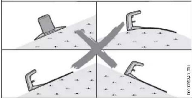
natural_image
Four-panel diagram showing a cross-shaped object with four tool-like shapes, no text or symbols present.text_image
90° a 1 0000089644_001text_image
Technical diagram illustrating a mechanical or fluid system with labeled components and directional arrows, including annotations 'a', 'b', and 'c'.text_image
Technical diagram showing a device with cable and connector, including a magnified inset view of the component's internal structure.natural_image
Diagram of a mechanical device with a lever and cable, connected to a wall (no text or symbols visible)text_image
1 000000054_001text_image
Technical diagram of a mechanical device with numbered components and directional arrows indicating assembly or movement.natural_image
Technical diagram of a mechanical assembly with arrows indicating assembly direction (no text or symbols present)text_image
Technical diagram of a mechanical component with numbered parts and directional arrows indicating assembly or flow.natural_image
Technical illustration showing a mechanical device with pins and a separate image of three vertical pins (labeled '8'), no text or symbols present.text_image
a 0000039959_0011text_image
Technical diagram showing mechanical assembly with labeled parts and a magnified inset highlighting a component detail.text_image
Diagram of a mechanical device with labeled parts and a wire spool, showing components 1 and 3.text_image
Diagram of a mechanical device with labeled parts and wiring, showing a lever mechanism and a spool.text_image
Diagram of a mechanical device with labeled parts 1, 2, and 3, connected by a wire to a spool on a grid background.text_image
Diagram showing a mechanical assembly with labeled parts and a magnified detail view of a component being inserted into a wire.text_image
1 2 3 4 C000100295_001text_image
Technical diagram showing mechanical assembly with labeled parts and a magnified inset highlighting a component detail.text_image
Technical diagram showing a mechanical assembly with labeled components and directional arrows, including parts 1 and 3.text_image
a 0000100053_001text_image
a 000010058_001text_image
Diagram showing a vehicle with a road, a brain icon, a skull, and a cross symbol, possibly representing a road or navigation system.text_image
Diagram illustrating a mechanical or optical setup with labeled components and a magnified view of a tool tip interacting with a wire.natural_image
Line drawing of a robotic lawn mower on a paved surface next to brick walls (no text or symbols)text_image
a 0000100063_001text_image
a 1 a a 1 b 0000100055_001natural_image
Diagram of a robotic arm with a labeled measurement 'a' between two circular objects on a textured surface (no text or symbols beyond the label)natural_image
Line drawing of a car driving on a path with trees and a directional arrow (no text or symbols)text_image
Technical diagram showing mechanical assembly with labeled parts and a magnified view of tool pathtext_image
Diagram illustrating a mechanical setup with labeled components and a magnified inset showing parts numbered 1 and 2.text_image
Technical diagram showing a sewing machine tool with labeled parts and a spool, including numbered callouts.text_image
1 5 0000100415_001text_image
Technical diagram of a mechanical device with labeled parts and an inset showing a component with arrows and numbered callouts.text_image
Technical diagram showing a mechanical assembly with labeled components and a close-up of a tool interacting with a device labeled 1, 2, and 3.text_image
Technical diagram showing a sewing machine setup with labeled parts and a magnified view of the tool's cutting process.text_image
5 1 0000100245_001text_image
STINL 1 6 0000100246_001text_image
Technical diagram of a mechanical assembly with labeled parts and an inset showing a disassembly or disassembly process.text_image
a 000010226_001text_image
1 4 0000100238_001text_image
Technical diagram showing a mechanical assembly with numbered components and a spool, likely illustrating a device or component layout.text_image
Technical diagram showing mechanical assembly steps with numbered components and checkmark indicatorstext_image
1 8 8 0000100231_001text_image
Technical diagram showing a tool assembly with labeled parts 1 and 2, including pliers and component layouts.text_image
Technical diagram showing a tool in a mechanical assembly with labeled parts and a checkmark indicating approval.text_image
R 1 L 3 0000100250_001natural_image
Mechanical assembly diagram showing a component labeled '4' with no visible text or symbols beyond the number and reference number.natural_image
Illustration of a person adjusting a car with a hand on the phone (no text or symbols visible)text_image
Technical diagram showing three views of a robotic device with labeled parts: front view, interior control panel, and rear view.14.2 LED sulla docking station
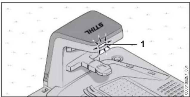
text_image
STIL 1▶ Premere "INFO" (5).
text_image
Diagram of a vacuum cleaner with labeled parts and a magnified inset showing internal componentstext_image
1 2 0000009963_001text_image
Diagram of a device with labeled parts and an inset showing a control panel with buttons and indicators.natural_image
Mechanical device with a downward arrow and connector, no visible text or symbolstext_image
Diagram showing a device with arrows indicating process, including an inset image of a hand using a device.▶ Smontare la docking station.
19 Pulizia
19.1 Pulizia del robot rasaerba

AVVERTENZA
text_image
Technical diagram of a mechanical device with numbered components and an inset highlighting a keyhole.natural_image
Technical line drawing of a mechanical device with hands operating it, no visible text or symbolsnatural_image
Technical line drawing of a mechanical component with concentric rings and a labeled section (no text or symbols)natural_image
Technical line drawing of a robotic car with visible gears and wheel assembly (no text or symbols)text_image
Technical diagram of a robotic lawn mower with labeled parts 1 and 2text_image
7 7 7 0000100284_001natural_image
Technical diagram of a mechanical component with labeled parts (no text or symbols beyond labels)text_image
Technical diagram showing mechanical assembly steps with labeled components and checkmark indicatorstext_image
a 0000100242_001Energy 5.0 e supportare Generic Access Profile (GAP).
Robert Olma, Vice President, Regulatory Affairs & Global Governmental Relations
27 Software Open Source
27.1 Software Open Source
text_image
1 2 3 4 5 6 0000099354_0011 Voorste handgreep
De ultrasoundsensoren herkennen obstakels.
4 Kap
text_image
9 8 7 10 00000059822_0017 Achterste handgreep
text_image
Labeled diagram of a device with numbered components and a cable, showing parts 1 through 11.1 Netstekker
natural_image
Technical illustration showing a row of five nail tips and a mechanical device with pins (no text or symbols)12 Grondpen
1 led brandt rood. De accu is te warm of te koud.


flowchart
graph TD
    A["Vehicle"] -->|5| B["Road marked 'B'"]
    B -->|4| C["Road marked 'A'"]
    C -->|4| D["Road marked 'B'"]
    style A fill:#f9f,stroke:#333
    style B fill:#ccf,stroke:#333
    style C fill:#cfc,stroke:#333
    style D fill:#fcc,stroke:#333
text_image
6 8 7 000100413_001text_image
Illustration showing various objects including a soccer ball, apple, pencil, brush, and a cross symbol with a speech bubble containing 'a'.natural_image
Line drawing of a robotic lawn mower on a rural path with grassy background (no text or symbols)text_image
a 000009825_001text_image
00000099842_001 1 WI-FInatural_image
Simple line drawing of a mechanical component with a checkmark indicating selection (no text or symbols)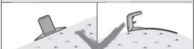
natural_image
Two abstract geometric shapes: a gray tower-like shape and a black curved form, both on a textured surface (no text or symbols)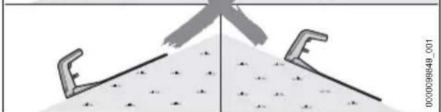
natural_image
Diagram showing two tool holders merging into a triangular pile with a central blade (no text or symbols)text_image
Technical diagram showing a device with cable and connector, including a magnified inset view of the component's internal structure.natural_image
Diagram of a mechanical device with a magnified inset showing a close-up view (no text or symbols present)text_image
Technical diagram showing a device with labeled parts and an inset magnified view of a component with directional arrows.text_image
Technical diagram of a mechanical device with numbered components and directional arrows indicating assembly or movement.natural_image
Technical diagram of a mechanical assembly with arrows indicating assembly direction (no text or symbols present)text_image
Technical diagram of a mechanical component with numbered parts and directional arrows indicating assembly or flow.natural_image
Technical illustration showing a mechanical device with pins and a separate image of three vertical pins (labeled '8'), no text or symbols present.text_image
a 0000096959_001text_image
Technical diagram showing mechanical assembly with labeled parts and a magnified detail view of a componenttext_image
Technical diagram showing a mechanical assembly with numbered components and a magnified inset view of a component.text_image
Diagram of a mechanical device with labeled parts 1, 2, and 3, connected by a wire to a spool on a grid background.text_image
Diagram of a mechanical device with labeled parts and connection points, including a spool and coil system.text_image
Diagram of a mechanical device with labeled parts 1, 2, and 3, showing a wire connection to a spool on a grid background.text_image
Technical diagram showing a cable being inserted into a component with labeled parts and a magnified inset view of the cable's internal structure.text_image
Technical diagram showing a mechanical assembly with labeled parts and a magnified inset highlighting a specific component.text_image
Technical diagram showing a mechanical assembly with numbered components and a magnified inset view labeled 4text_image
Technical diagram showing a mechanical assembly with labeled components and directional arrows, including parts 1 and 3.text_image
1 a b 2 c 000009843_001text_image
a 0000100053_001text_image
a 000010058_001text_image
Diagram showing a vehicle with a road, a brain icon, a skull, and a cross symbol, possibly representing a road or navigation system.text_image
Diagram illustrating a mechanical or optical setup with labeled components and a magnified view of the tool tip.natural_image
Line drawing of a robotic vacuum cleaner on a tiled floor next to brick walls (no text or symbols)text_image
a 0000100062_001text_image
a 0000100063_001text_image
a a 1 b 0000100055_001natural_image
Line drawing of a car driving on a path with trees and a directional arrow (no text or symbols)text_image
Technical diagram showing a sewing machine setup with labeled parts and a magnified view of the tool path.text_image
Diagram showing mechanical assembly with labeled parts and a magnified inset showing component 2text_image
Diagram illustrating a mechanical assembly process with labeled components and directional arrows, including a magnified view of the tool path.text_image
1 5 0000100415_001text_image
STINL 1 7 000010046_001text_image
Technical diagram showing a mechanical assembly with labeled components and a close-up of a tool interacting with a device labeled 1, 2, and 3.text_image
Technical diagram showing a mechanical assembly with labeled parts and a magnified inset of a hand holding a tool.text_image
5 1 0000100245_001text_image
Technical diagram of a mechanical assembly with labeled parts and a spool, showing internal components and directional arrows.text_image
a 000100236_001text_image
Technical diagram showing mechanical assembly with labeled parts and a wire spool, likely illustrating a cable or fiber connection.text_image
Technical diagram of a mechanical assembly with numbered components and a spool, likely for maintenance or assembly instructions.text_image
Technical diagram showing mechanical assembly steps with numbered components and checkmark indicatorstext_image
1 8 8 0000100231_001text_image
Technical diagram showing a tool application with labeled parts 1 and 2, including pliers and mechanical components.text_image
Technical diagram showing a mechanical assembly with labeled parts and a checkmark indicating approval or confirmation.natural_image
Mechanical component diagram showing a connector with labeled part 4 (no text or symbols beyond label)text_image
5 YILLS 000010293_001text_image
a 0000102260_001natural_image
Line drawing of a person using a car to adjust or install a vehicle (no text or symbols visible)text_image
1 2 3 4 5 STOP INFO STTRL-000009962_001text_image
Diagram of a robotic vacuum cleaner with labeled parts and a zoomed-in view showing internal components.▶ Druk op „STOP“ (1).
De maairobot wordt gestopt en vergrendeld.
▶ Druk op „STOP“ (1) en houd de knop net zolang ingedrukt totdat de lichtstrook (2) volledig rood brandt.
▶ Druk op „STOP“ (1).
text_image
Diagram of a device with labeled parts and an inset showing a control panel with buttons and a timer.natural_image
Mechanical device with a downward arrow indicating force or motion, no visible text or symbolstext_image
Diagram showing a device with arrows indicating force application, alongside an inset image of a hand pressing a component.natural_image
Technical line drawing of a mechanical device with hands operating it, no visible text or symbolsnatural_image
Technical line drawing of a mechanical component with concentric rings and a labeled section (1), no readable text or symbols present.natural_image
Technical line drawing of a robotic arm with visible gears and housing, showing internal components and a close-up inset (no text or symbols)text_image
Technical diagram of a robotic lawn mower with labeled parts 1 and 2text_image
7 7 7 0000100284_001natural_image
Technical illustration of a mechanical component with labeled parts (no text or symbols beyond labels)text_image
Technical diagram showing mechanical assembly steps with labeled components and checkmark indicatorstext_image
a 0000100242_001– Maximale helling: 45%
Bluetooth®
- LTE-Cat-M1: B1, B2, B3, B4, B5, B8, B12, B13, B20, B28, B66
- UMTS, HSDPA, HSPA+: B1, B2, B4, B5, B6, B8, B19
– GSM, GPRS, EDGE: 850 MHz, 900 MHz, 1800 MHz, 1900 MHz
Robert Olma, Vice President, Regulatory Affairs & Global Governmental Relations
Robert Olma, Vice President, Regulatory Affairs & Global Governmental Relations
28 Open Source-software
28.1 Open Source-software
text_image
Image displaying a vertical column of evenly spaced black horizontal lines on white background, resembling a barcode or pattern.0458-012-9601-A