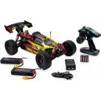
Virus 4.0 6S Brushless - Remote control toy Carson - Free user manual and instructions
Find the device manual for free Virus 4.0 6S Brushless Carson in PDF.


| Product type | Remote-controlled off-road car |
| Brand | Carson |
| Model | Virus 4.0 6S Brushless |
| Motorization | Brushless motor |
| Power supply | LiPo 6S battery (22.2 V) not included |
| Dimensions (approx.) | 500 x 300 x 200 mm |
| Weight (approx.) | 3.5 kg |
| Scale | 1/8 |
| Drivetrain | 4-wheel drive (4WD) |
| Radio frequency | 2.4 GHz |
| Radio range | Up to 100 m |
| Maximum speed (est.) | Up to 80 km/h |
| Functions | Forward, reverse, brake, proportional steering |
| Spare parts | Available from Carson dealers or online |
| Maintenance | Clean after use, check screws and nuts, lubricate bearings |
| Safety | Do not use on public roads, keep distance, check before each use |
| Certifications | CE, compliance with European directives |
| Warning | This product is not a toy; use under adult supervision for children under 14 years |
Frequently Asked Questions - Virus 4.0 6S Brushless Carson
User questions about Virus 4.0 6S Brushless Carson
0 question about this device. Answer the ones you know or ask your own.
Ask a new question about this device
Download the instructions for your Remote control toy in PDF format for free! Find your manual Virus 4.0 6S Brushless - Carson and take your electronic device back in hand. On this page are published all the documents necessary for the use of your device. Virus 4.0 6S Brushless by Carson.
USER MANUAL Virus 4.0 6S Brushless Carson
Before using your product for the first time or ordering any spare parts, check that your manual is fully up-to-date.
This manual contains the technical appendices, important instructions for correct start-up and use and product information, all fully up-to-date before going to press.
The contents of this manual and the technical data of the product can change without prior notice.
For the latest version of your manual, see: www.carson-modellsport.com
FR // Remarque importante
natural_image
Four identical cylindrical batteries with plus and minus signs, arranged horizontally (no text or symbols beyond the plus/minus signs)natural_image
Simple line drawing of a rectangular object with three horizontal lines extending from its top, resembling a connector or cable (no text or symbols)natural_image
Line drawing of a hand using a tool to cut a car wheel (no text or symbols)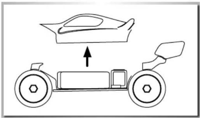
natural_image
Diagram of a car chassis with an upward arrow indicating motion or force (no text or symbols present)auFLaDen DeS FaHraKKuS
AcHTuNG!
natural_image
Simple line drawing of a battery connected to a light bulb via wires (no text or symbols)eInLegen Der FaHraKKuS
natural_image
Line drawing of a hand operating a vehicle chassis with visible motors and wheels (no text or symbols)natural_image
Illustration of hands assembling or connecting a component with wires, no text or symbols presentSteuern DeS moDeLLS
natural_image
Diagram of a car's front suspension system with two tire tracks and a steering wheel (no text or symbols)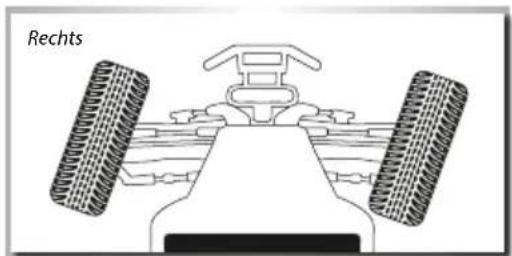
natural_image
Diagram of a vehicle showing front wheel, rear wheels, and central body (no text or symbols)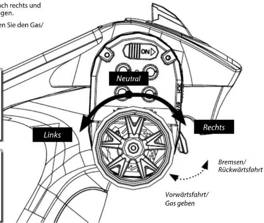
We congratulate you for buying this CARSON product, which is designed and manufactured using state of the art technology.
According to our policy of continued development and product improvement we reserve the right to make changes in specifications regarding equipment, material and design at any time without notice.
Specifications or designs of the actual product may vary from those shown in this manual or on the box.
The manual forms part of this product. Should you ignore the operating and safety instructions, the warranty will be void.
Keep this guide for future reference.
Limited Warranty
This product is warranted by CARSON against manufacturing defects in materials and workmanship under normal use for 24 months from the date of purchase from authorised franchisees and dealers. In the event of a product defect during the warranty period, return the product along with your receipt as proof of purchase to any CARSON store.
CARSON will, at its option, unless otherwise provided by law:
(a) Correct the defect by repairing the product without charging for parts and labour;
(b) Replace the product with one of the same or similar design.
All replacement parts and products, and products on which a refund is made, become the property of CARSON. New or reconditioned parts and products may be used in the performance of warranty services.
Repaired or replaced parts and products are warranted for the remainder of the original warranty period. You will be charged for repair or replacement of the product made after the expiration of the warranty period.
The Warranty does not cover:
- Damage or failure caused by or attributable to acts of God, abuse, accident, misuse, improper or abnormal usage, failure to follow instructions, improper installation or maintenance, alteration,
lightning or other incidence of excess voltage or current;
• Damage caused by losing control of your model; - Any repairs other than those provided by a CARSON authorised service facility;
• Consumables such as fuses or batteries; - Cosmetic damage;
• Transportation, shipping or insurance costs; or - Costs of product removal, installation, set-up service adjustment or reinstallation;
- Any changes to plugs and cables, open the housing and damage the sticker.
This warranty gives you specific legal rights, and you may also have other rights which may vary according to the country of purchase.
Declaration of Conformity
Dickie Tamiya GmbH & Co. KG hereby declares that this model kit with radio, motor, battery and charger is in accordance with the basic requirements of the following European directives: 98/37 EC and 89/336/EEC and other relevant regulations of guideline 1999/5/EC (R&TTE).
The original declaration of conformity can be obtained from the following address:
The explanation of the symbol on the product, packaging or instructions: Electronic devices are valuable products and should not be disposed of with the household waste when they reach the end of their service life! Help us to protect the environment and respect our resources by handing this appliance over at the relevant recycling points.

We hope your new Carson model gives you much pleasure.
Before use, read this manual carefully!
contentS
Preface 10
Included Items Accessories....11
Safety Precautions....12
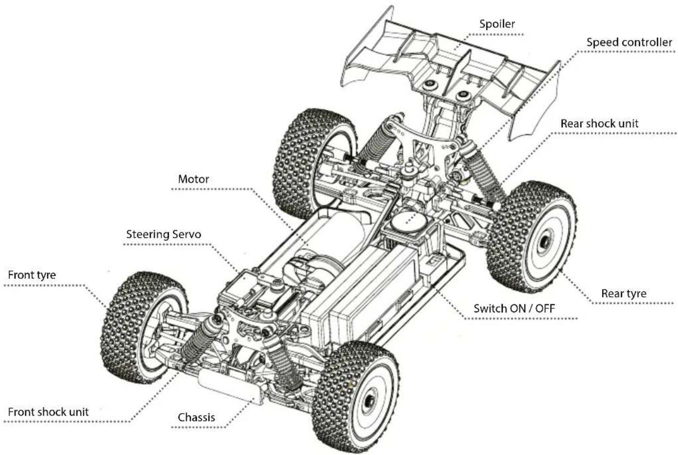
Chassis....13
Removing the Body 13
Charge battery pack....14
Inserting the drive battery 14
Turn on the RC System....15
How to Control Your Model....15
Troubleshooting....16
Assembly instructions 21
Spare Parts 39
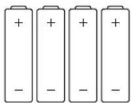
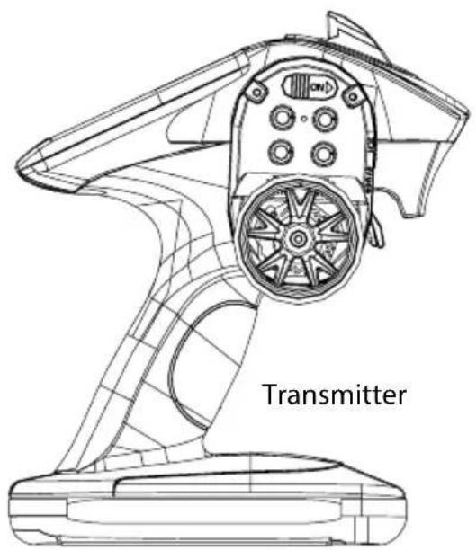
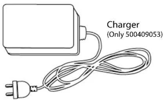
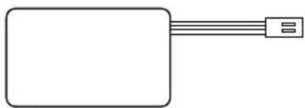
IncLuDeD ItemS acceSSorleS
natural_image
Four identical cylindrical batteries with plus and minus signs, arranged horizontally (no text or symbols beyond polarity indicators)Batteries (Only 500409053)
natural_image
Simple line drawing of a rectangular object with three horizontal lines extending from its top, resembling a connector or cable (no text or symbols)2x Driving battery pack (Only 500409053)
SaFety PrecautionS
Safety Instructions and Intended Use
This product is designed exclusively for hobby use and may only be used on tracks and areas intended for this purpose.
No persons or animals may be transported with this model.
To avoid operator errors, it is mandatory that the user manual is read before use!
These models may only be used with bodywork that is correctly fitted.
When removing the bodywork, please note that, during operation, certain parts can become very hot.
Please note that various models can generate very high noise levels and should, therefore, not be operated in your immediate proximity.
Please make sure, before every driving session, that the tank is correctly closed or the power pack is correctly inserted.
To avoid faulty operation of the control system causing the model to run out of control, it must be checked that the transmitter and model batteries are in good condition.
It is essential to check that the model is correctly assembled both before and after use; if need be, tighten nuts and bolts.
This model is not a toy!
- This product is not a toy, its operation must be learned step by step.
• Children under 14 years of age should operate the model only if supervised by an adult.
Operating RC models is a fascinating hobby that, however, must only be exercised with proper precautions and care. Since the weight of this model is considerable and it can reach a very high speed it can, if it runs out of control, cause significant damage and injury for which you, as the operator, are liable.
Only a correctly assembled model will work and react as expected.
Never improvise with unsuitable materials but, when the need arises, use only original spare parts. Even if the model is pre-assembled, all joints and fastenings should be checked for correct seating and tightness.
Before use, you must make sure of the following points:
• All rechargeable batteries must be fully charged.
• Before starting, check the radio range.
- Check that the model reacts correctly to the control signals.
- All functional parts of the product are in a faultless condition and have been checked.
• All screw fastenings are firmly seated.
- Do not drive under high-voltage power lines or radio masts or with nearby thunderstorms!
• Atmospheric interference can influence the operation of your model.
- The electrical parts of the model are not water-tight. Do not, therefore, drive it in rain or snow or through puddles or wet grass.
- The remote controlled model may be driven only on suitable areas and must not be used on the public highway.
• Do not use near people or animals!
- Do not use it when tired or if your reactions are otherwise impaired.
• Always maintain direct visual contact with your model.
- Regular maintenance and care are required for first class driving performance.
- The model has parts that become hot in operation, e.g. the top of the motor, the metal gearbox, amongst many others. Touching these parts during operation can cause injury.
Pay attention to the charge level indication on your transmitter.
- With power packs or batteries that are half discharged, you can lose control of the model.
- In the transmitter, never mix fully charged batteries, rechargeable or not, with half discharged batteries or rechargeable batteries of different capacity.
- Never try to charge non-rechargeable batteries (dry cells), only batteries specified as rechargeable can be charged.
cHaSSIS
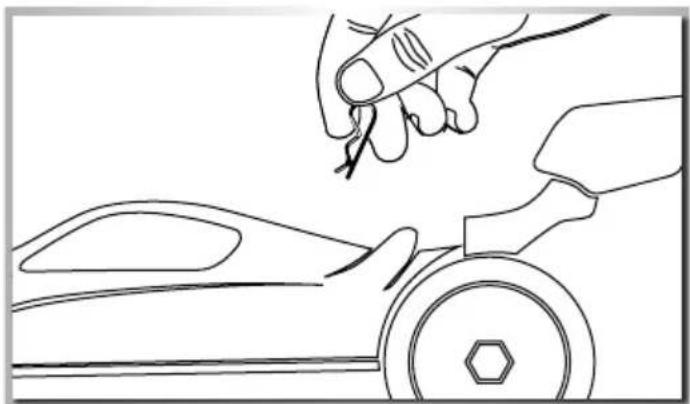
remoVIng tHe boDy
- Remove hook pin and - Take body off.
natural_image
Line drawing of a hand using a tool to cut or mark a car wheel (no text or symbols)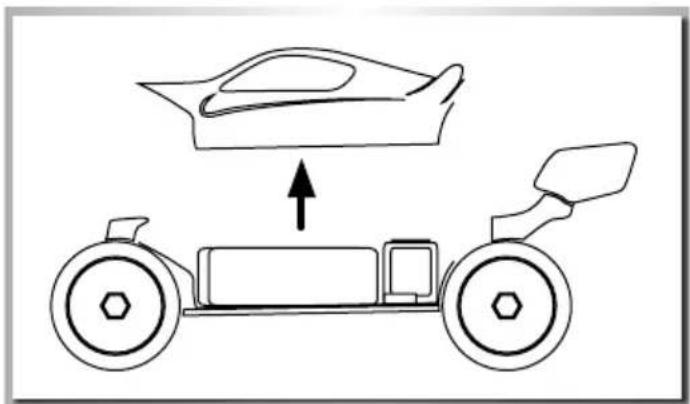
natural_image
Diagram of a car chassis with an upward arrow indicating motion or force, showing no text or symbols.cCharge battery PacK
Beware:
For charging the battery, only use the recommended charger. Please consider the advice of the enclosed instructions.
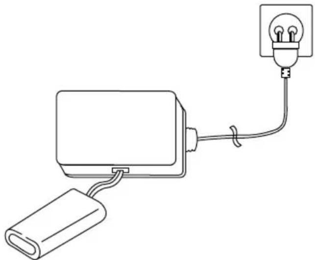
Charging procedure:
1 Connect the charger using the power lead supplied.
2 Connect it to a standard 100-240V socket. If all of the LEDs flash alternately for one second, the charger is ready to use.
3 Now connect the battery pack to the charger using the XHP balancer plug.
4 The charging process has now started.
5 The charger has a charging indicator lamp with four LEDs to indicate the status.
1st LED – battery pack has 25% capacity,
2nd LED - 50%,
3rd LED 75%. If all four LEDs glow, the battery pack is fully charged.
Error indication:
All four LEDs flash during the charging process (please check your battery pack).
natural_image
Simple line drawing of a bulb connected to a battery and cable (no text or symbols)InSertIng tHe DrIVe batterleS
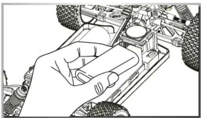
1 Insert the batteries
2 Put the battery plate on it and
3 Fix it with the hook pins.
Advice
• Non-rechargeable batteries are not to be recharged.
- Rechargeable batteries are to be removed from the toy before being charged.
- Rechargeable batteries are only to be charged under adult supervision.
- Batteries are to be inserted with the correct polarity.
• Exhausted batteries are to be removed from the toy.
• The supply terminals are not to be short-circuited.
- Regular examination of transformer or battery charger for any damage to their cord, plug, enclosure and other parts.
natural_image
Line drawing of a hand operating a vehicle chassis with no visible text or symbolsturn on tHe rc SyStem
CAUTION!
Always turn the transmitter's power switch ON first!
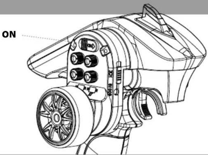
1 Connect the rechargeable battery for the driving.
2 Switch on the receiver.
3 Put the body on and fix it with the body split pins.

natural_image
Illustration of hands assembling or connecting a component with wires, no text or symbols presentHow to control your moDeL
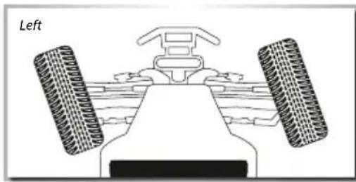
- Raise the tyres off the ground
- Turn the steering wheel to the right and left as far as it will go. The wheels are to follow the steering direction.
- If the wheels operate in the opposite direction, operate the servo Reverse switch (ST in position REV).
• To regulate the driving speed, actuate the throttle/brake - backwards (forward driving, accelerating) or
- forwards (braking, reversing)
natural_image
Diagram of a vehicle's front view showing steering wheel, dashboard, and rear wheels (no text or symbols)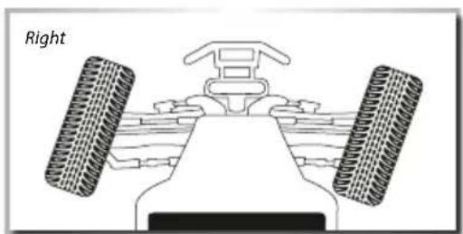
natural_image
Diagram of a vehicle's front view showing two tires and a steering wheel (no text or symbols)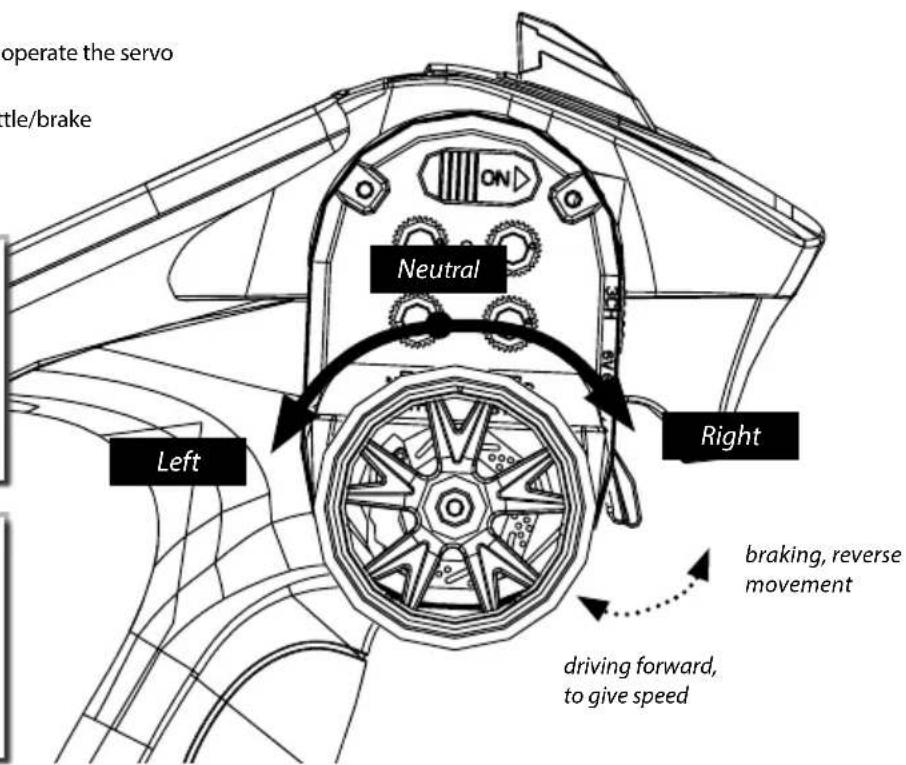
troubLeSHootIng
| Problem Cause Correction | ||
| Model doesn’t move Transmitter or chassis power switch is not "ON" | Switch power on receiver or transmitter | |
| Polarity or battery type is wrong Check polarity and type of battery | ||
| Batteries have run down Change batteries or charge them | ||
| Loss of control | Batteries have run down | Change batteries or charge them |
| Antenna is missing or not attached properly Attach receiver antenna | ||
| Doesn’t run straight | Steering trim is not adjusted correctly | Make adjustment |
| Front and rear wheel nuts are too lose Tighten wheel nuts | ||
| Doesn’t stop | Throttle trim is not adjusted correctly | Make adjustment |
| Doesn’t reverse | Throttle trim is not adjusted correctly | Make adjustment |
| Wrong action Control properly | ||
| Running too slowly | Batteries have run down | Change batteries or charge them |
| Motor has lost power | Change to spare motor | |
| Rear wheel nuts are too lose | Tighten wheel nuts | |
| Dust or foreign objects are inside gears | Turn the power switch "OFF" and clean out gears | |
Cher client
500908052 Silicon Oil 50 ml 1000
500908053 Silicon Oil 50 ml 3000
500908054 Silicon Oil 50 ml 5000
500908055 Silicon Oil 50 ml 7000
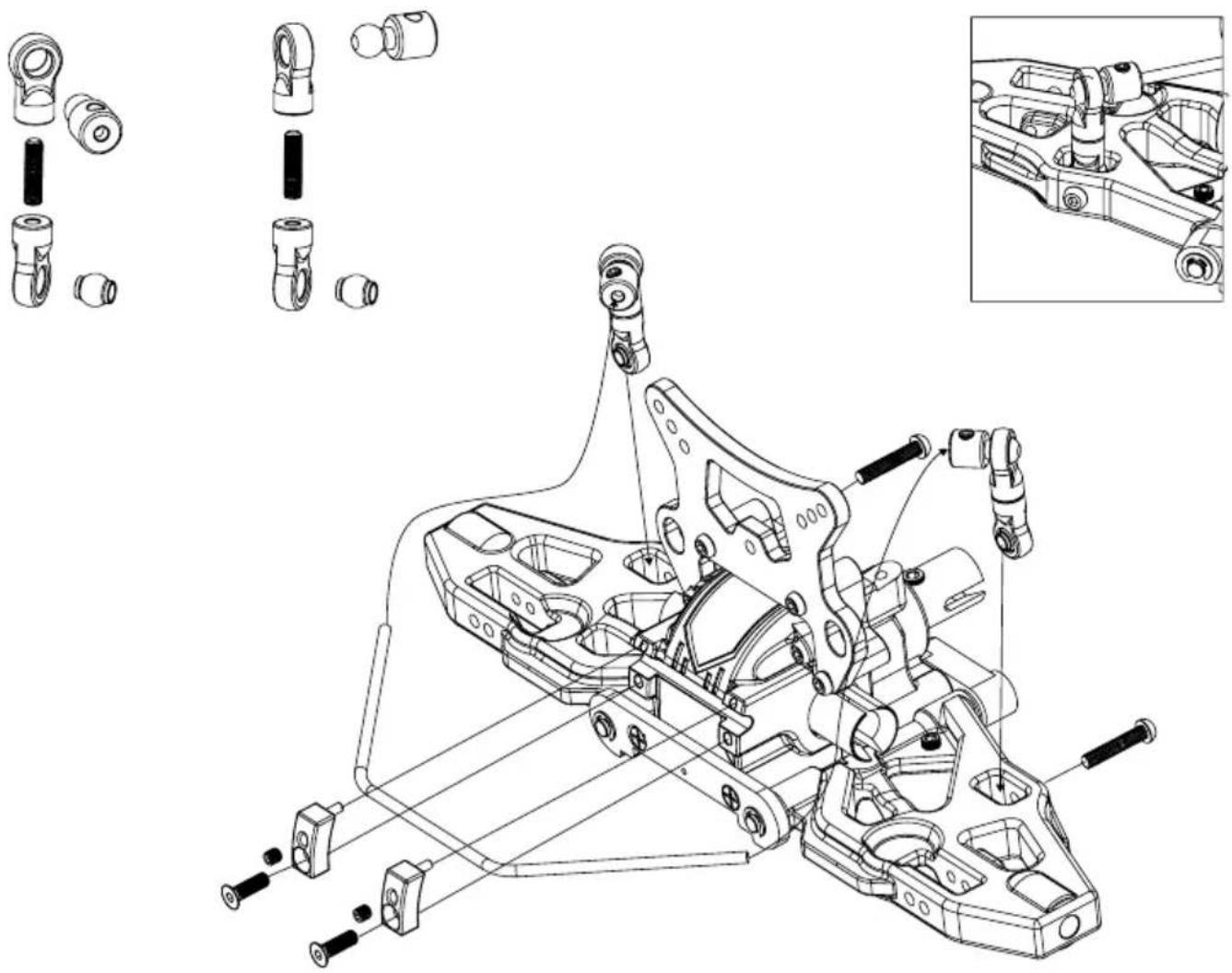
3. VORDERES DIFFERENZIAL • FRONT DIFFERENTIAL
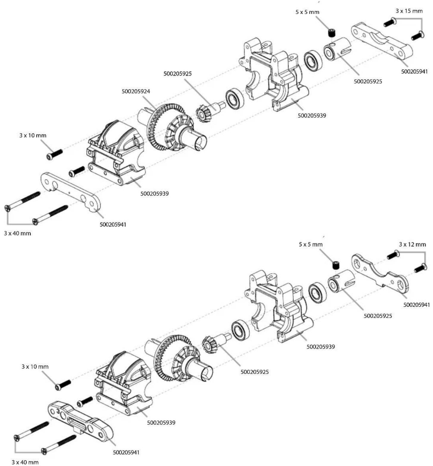
- MONTAGE VORDERACHSE • ASSEMBLING FRONT UNIT
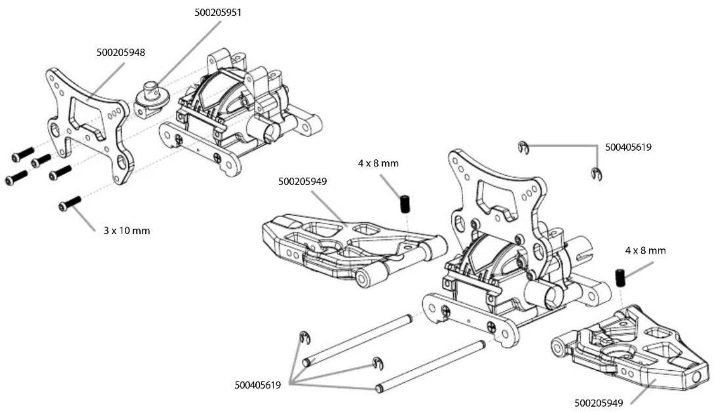
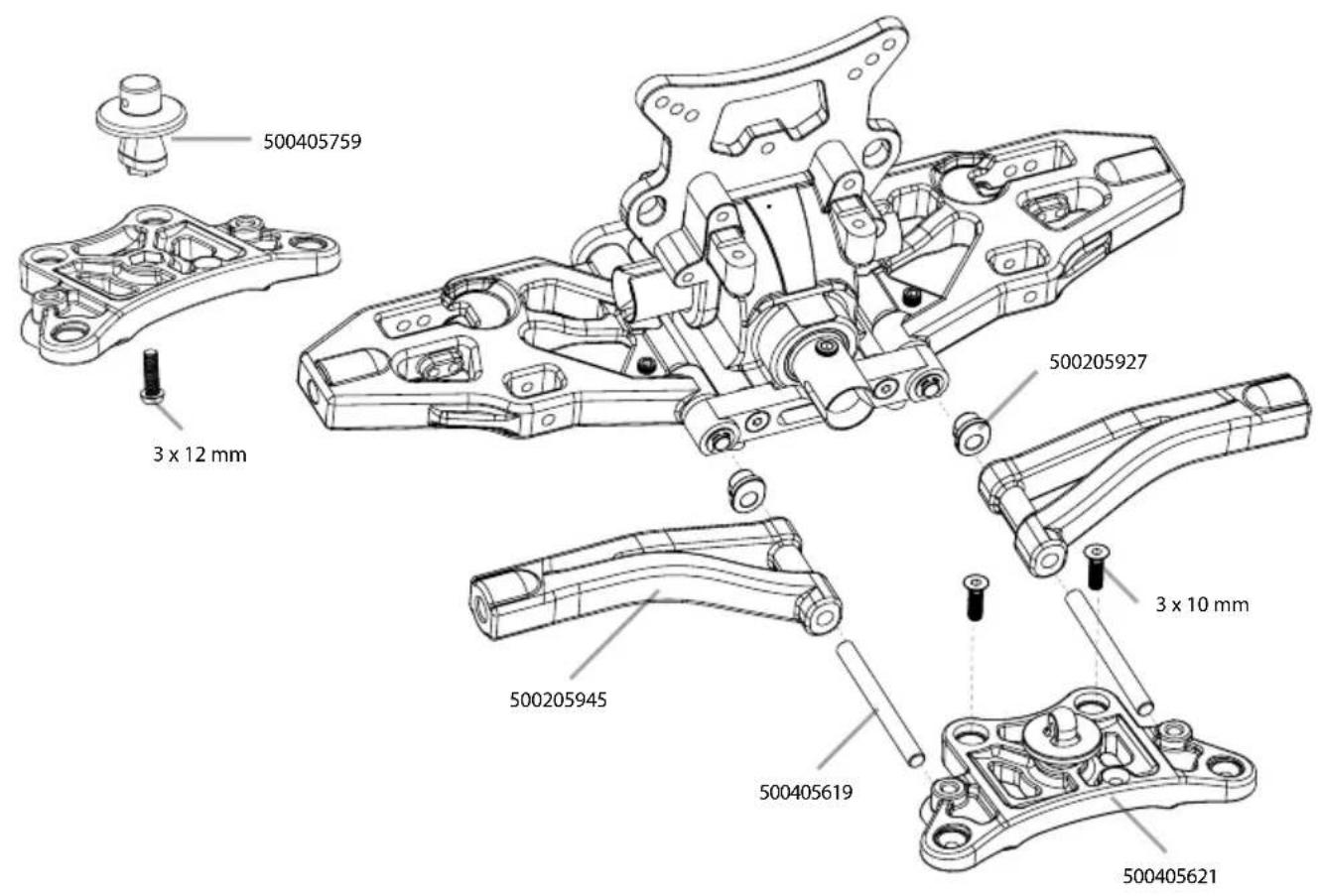
5. ACHSSCHENKEL VORNE • FRONT HUBS
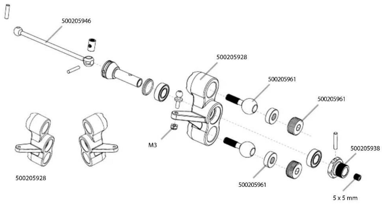
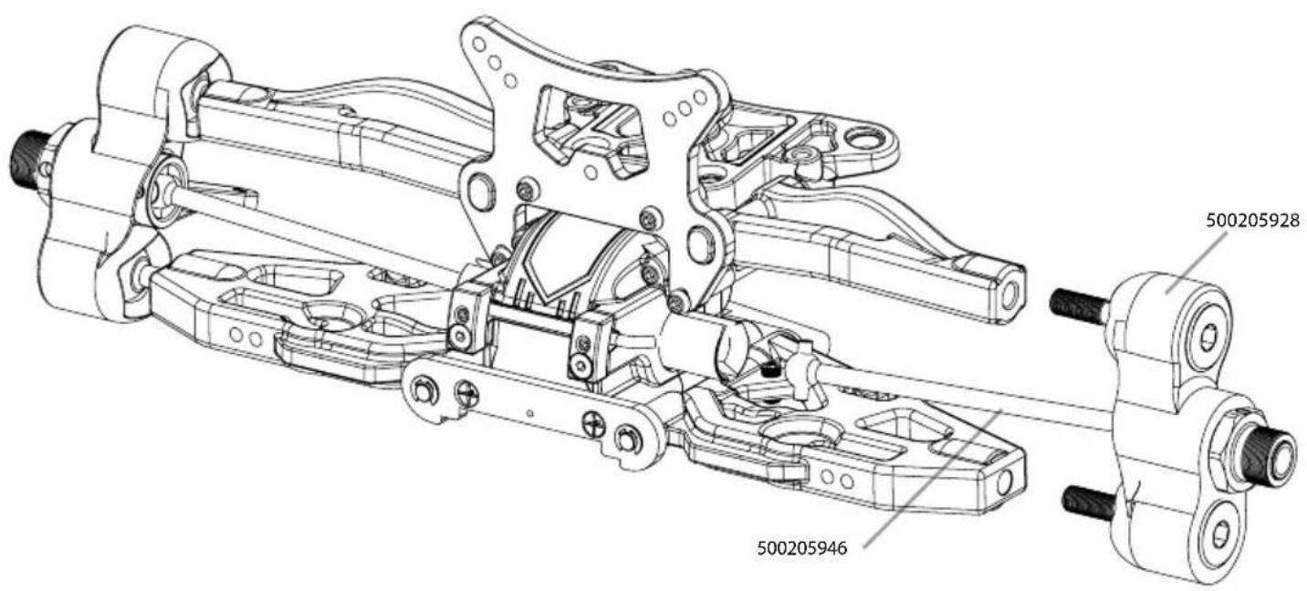
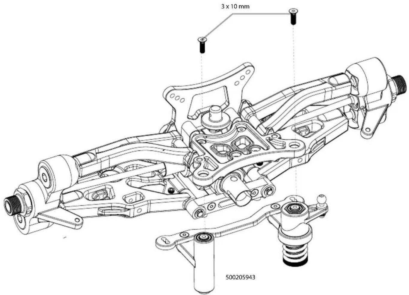
6. MONTAGE LENKUNG • ASSEMBLING STEERING
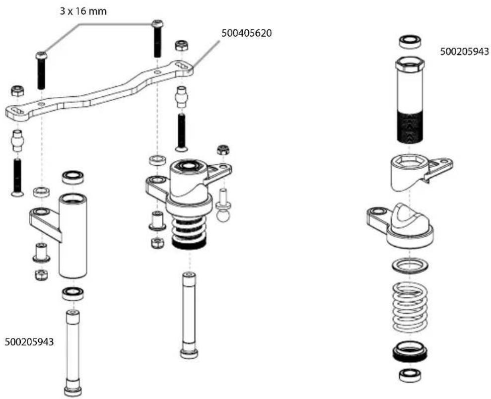
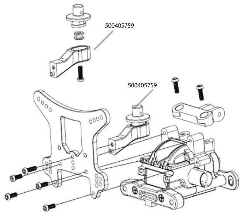
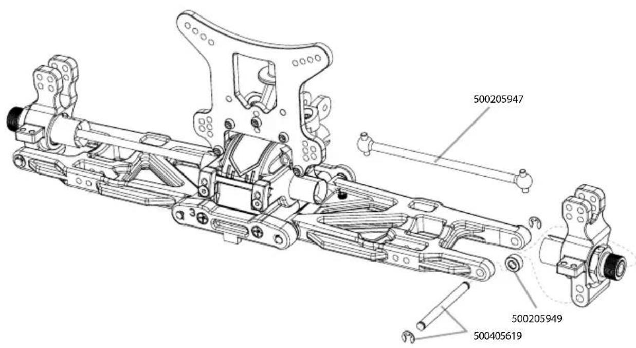
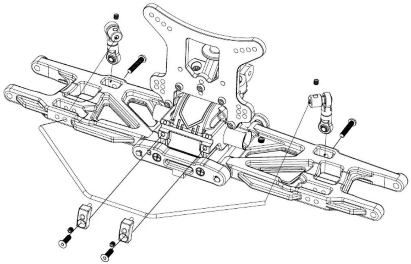
7. MONTAGE HINTERACHSE • ASSEMBLING REAR UNIT
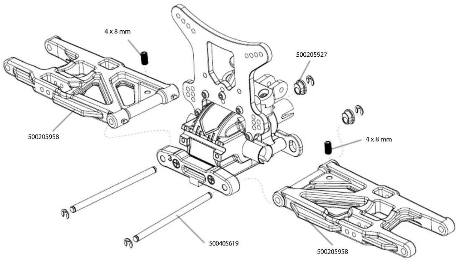
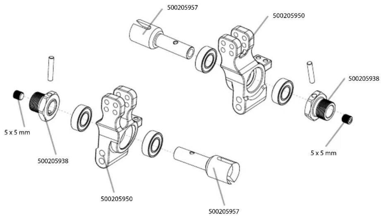
8. ACHSSCHENKEL HINTEN • REAR HUBS
natural_image
Technical line drawing of a mechanical assembly with exploded view (no text or labels)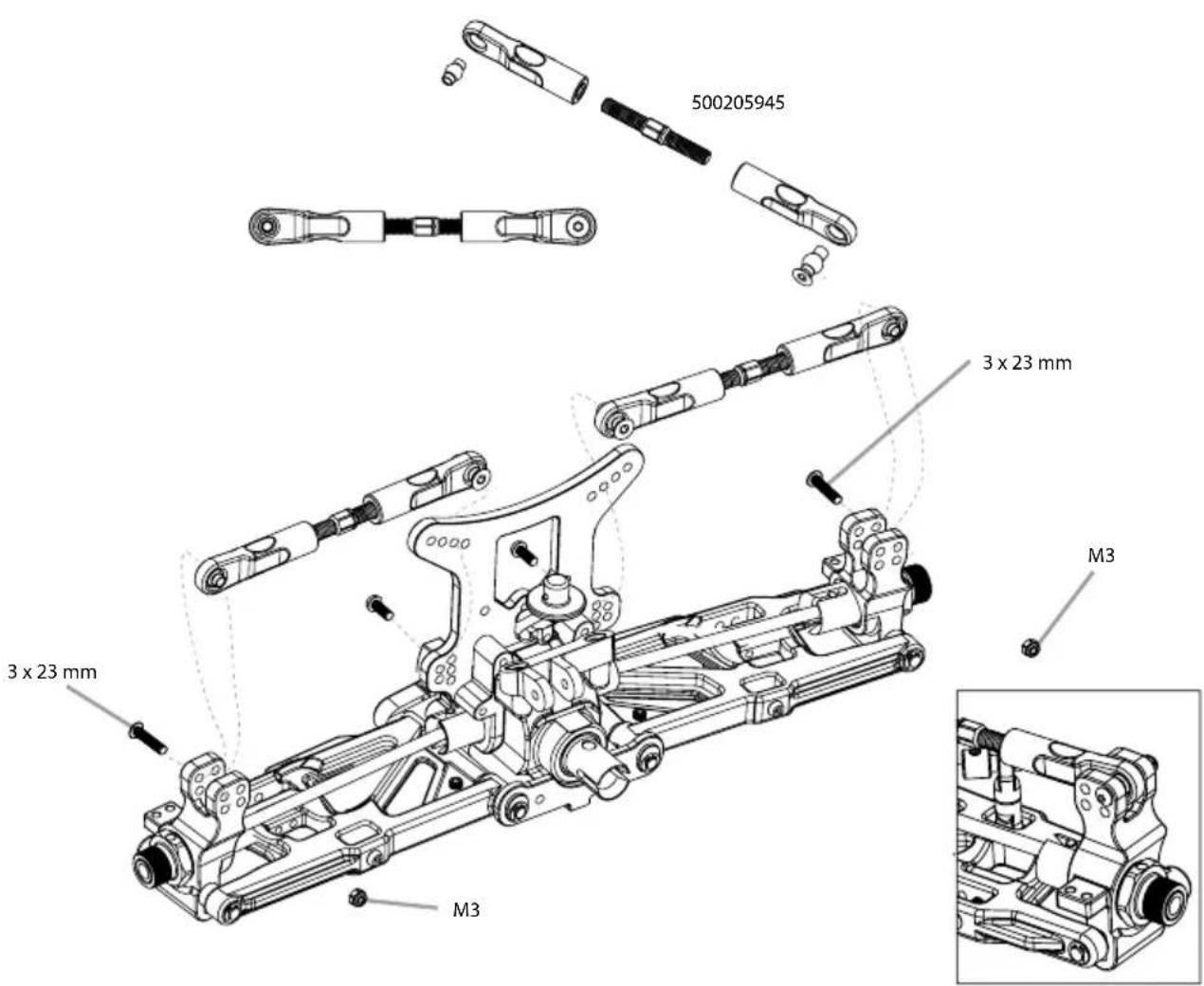
9. MONTAGE MOTOR • ASSEMBLING ENGINE
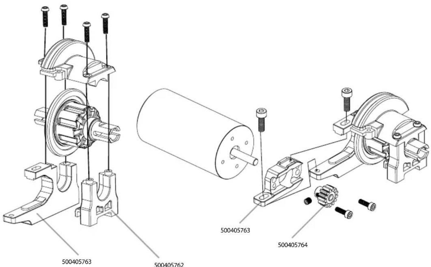
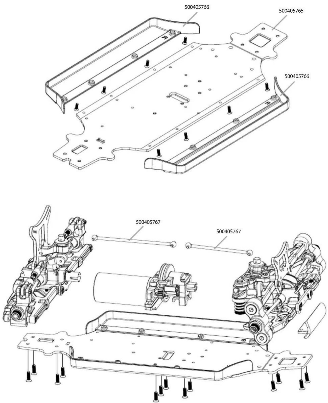
10. CHASSISPLATTE • CHASSIS-PLATE
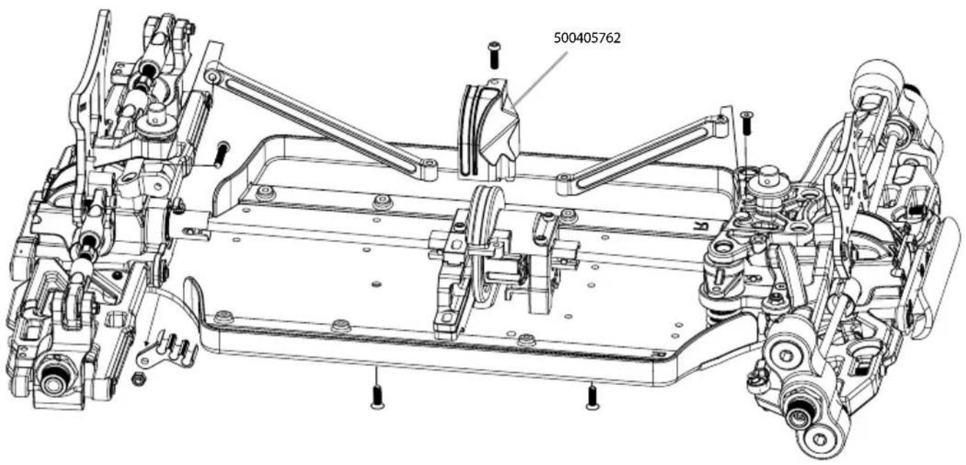
11. CHASSISVERSTEIFUNG • CHASSIS-BRACE
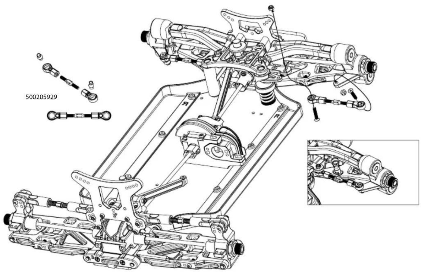
12. LENKGESTÄNGE • STEERING LINKAGE
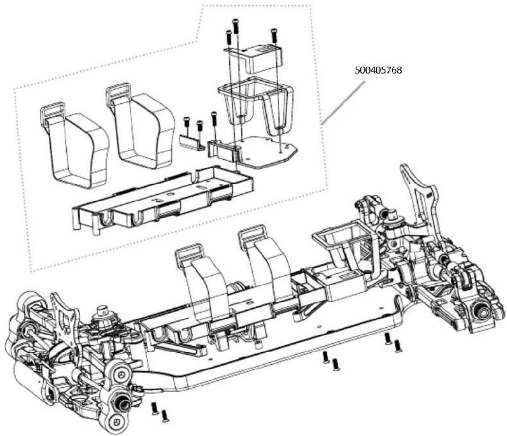
- AKKUHALTERUNG · BATTERYMOUNT
natural_image
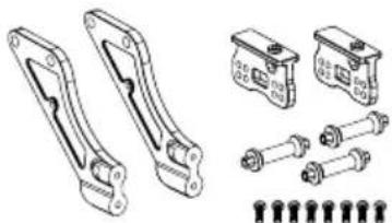
Technical line drawing of a gear and shaft assembly (no text or symbols)500205936 Wing mount posts
Spoilerhalterung
natural_image
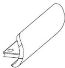
Technical line drawings of mechanical components including brackets, bolts, and housing (no text or symbols)500205942 Front bumper
Frontrammer
natural_image
Simple line drawing of a cylindrical object with a curved handle and a small protrusion (no text or symbols)natural_image
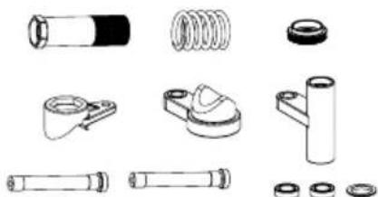
Technical illustration of four different types of mechanical springs or springs with separate assembly parts (no text or labels)500205943 Servosaver-Unit
Servosaver-Einheit
natural_image
Collection of mechanical components including bolts, springs, and flanges (no text or labels)natural_image
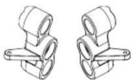
Technical line drawings of mechanical components (no text or symbols)500205928 Steering set (2)
Lenkhebel vorne (2)
natural_image
Technical line drawing of two mechanical clamping components (no text or symbols)natural_image
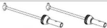
Technical line drawings of two mechanical components (no text or symbols)500205946 Front drive shafts (2)
Kardanwellen vorne (2)
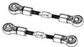
500205929 Steering linkage (2)
Lenkgestänge (2)
natural_image
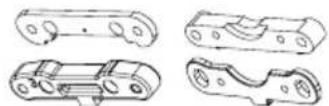
Two identical mechanical linkages with cylindrical ends and connectors, shown in line drawing style (no text or symbols)500205941 Lower suspension mount-kit Querlenkerhalter-Set
natural_image
Pure line drawing of two identical mechanical link components with mounting holes (no text or symbols)ERSATZTEILE • SPARE PARTS
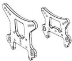
500205948 Shock towers front/rear (2)
Dämpferbrücken v/h (2)
natural_image
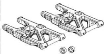
Technical line drawing of two mechanical bracket components (no text or symbols)500205958 Lower arms kit rear (2)
Querlenker-Set unten hi. (2)
natural_image
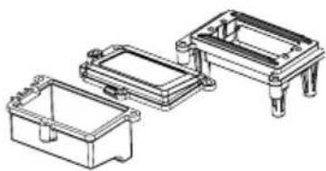
Technical line drawing of two mechanical brackets with mounting holes and circular seals (no text or symbols)500405591 RC-Box/Servomount
RC-Box/Servohalter
natural_image
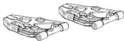
Technical line drawing of three mechanical components with mounting brackets (no text or symbols)500205949 Lower Arms kit front (2)
Querlenker-Set unten vo. (2)
natural_image
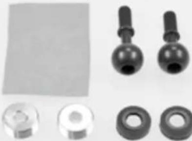
Technical line drawing of two mechanical components with no visible text or symbols500205961 Pivot-Ball Set
Pivot-Ball Set
natural_image
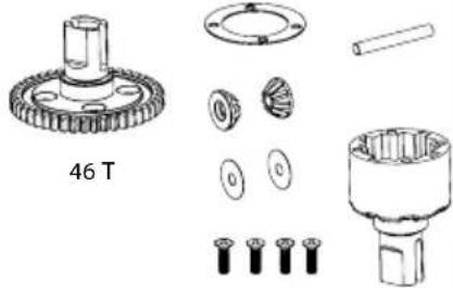
Collection of mechanical components including bolts, washers, and a plastic sheet (no text or symbols visible)500405592 Centerdiff complete Mitteldiff komplett
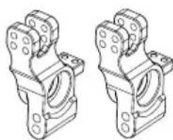
500205950 Rear hub carrier + Axle (2)
Achsschenkel hi. + Achsen (2)
natural_image
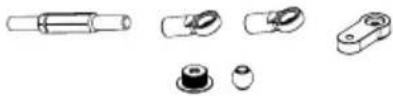
Technical line drawing of two mechanical bracket components (no text or symbols)500405588 Steering-link Lenkstange
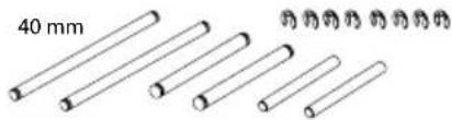
500405619 Hinge pins f. arms Querlenkerstifte
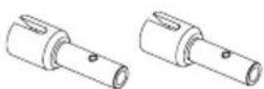
500205957 Axles rear (2)
Achsen hinten (2)
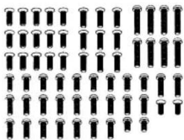
500405589 Schraubenset
Schraubenset
natural_image
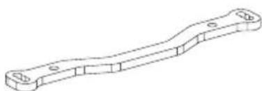
Grid of identical black cylindrical objects arranged in rows and columns (no text or symbols)500405620 Alu Steering rack Lenkplatte
natural_image
Technical line drawing of a mechanical bracket (no text or symbols)ERSATZTEILE • SPARE PARTS
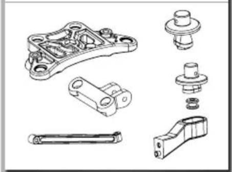
500405759 Karosseriehalter
Bodyholder kit
natural_image
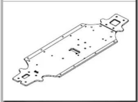
Exploded view diagram of mechanical parts including bracket, shaft, and housing (no text or labels)500405765 Chassis
Chassis
natural_image
Technical line drawing of a mechanical part with mounting flanges and internal features (no text or symbols)natural_image
Technical line drawing of two mechanical components with mounting holes (no text or symbols)500405762 Mitteldiffhalter-Set
Centerdifferential cover

natural_image
Technical line drawings of mechanical components (no text or symbols)natural_image
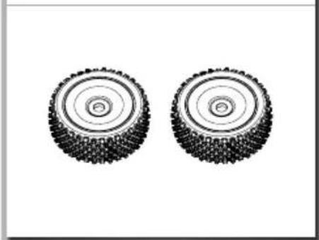
Technical line drawing of two mechanical brackets with mounting holes (no text or symbols)500405770 Räderset(2)
Wheel set
natural_image
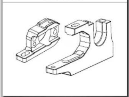
Two identical mechanical tire designs shown side by side (no text or symbols)500405763 Motorhalter Motorholder
natural_image
Technical line drawing of two mechanical bracket components (no text or symbols)natural_image
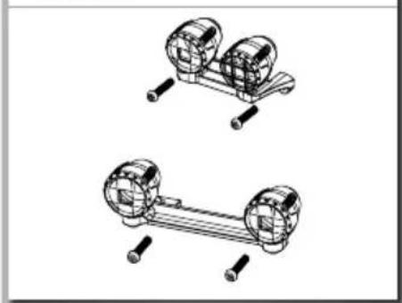
Two identical cylindrical metal rods with circular end caps, shown side by side (no text or symbols)500405771 LED Halterung
LED Holder
natural_image
Technical line drawing of two mechanical components with bolts and shafts (no text or symbols)500405764 Motorritzel Piniongear
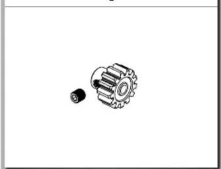
natural_image
Technical illustration of a gear and a small mechanical component (no text or symbols)500405768 Akkuhalter Set Battery holder
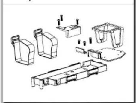
natural_image
Exploded view diagram of a mechanical assembly with multiple housing components (no text or labels)notlZen / noteS

CARSON-Model Sport

- FR // Remarque importante
- auFLaDen DeS FaHraKKuS
- AcHTuNG!
- eInLegen Der FaHraKKuS
- Steuern DeS moDeLLS
- Limited Warranty
- The Warranty does not cover:
- Declaration of Conformity
- contentS
- IncLuDeD ItemS acceSSorleS
- SaFety PrecautionS
- Safety Instructions and Intended Use
- This model is not a toy!
- Before use, you must make sure of the following points:
- Pay attention to the charge level indication on your transmitter.
- cHaSSIS
- remoVIng tHe boDy
- cCharge battery PacK
- Beware:
- Charging procedure:
- Error indication:
- InSertIng tHe DrIVe batterleS
- Advice
- turn on tHe rc SyStem
- CAUTION!
- Always turn the transmitter's power switch ON first!
- How to control your moDeL
- Cher client
- VORDERES DIFFERENZIAL • FRONT DIFFERENTIAL
- ACHSSCHENKEL VORNE • FRONT HUBS
- MONTAGE LENKUNG • ASSEMBLING STEERING
- MONTAGE HINTERACHSE • ASSEMBLING REAR UNIT
- ACHSSCHENKEL HINTEN • REAR HUBS
- MONTAGE MOTOR • ASSEMBLING ENGINE
- CHASSISPLATTE • CHASSIS-PLATE
- CHASSISVERSTEIFUNG • CHASSIS-BRACE
- LENKGESTÄNGE • STEERING LINKAGE
- ERSATZTEILE • SPARE PARTS
- CARSON-Model Sport
Brand : Carson
Model : Virus 4.0 6S Brushless
Category : Remote control toy