
CM 2204 - Receiver CREST AUDIO - Free user manual and instructions
Find the device manual for free CM 2204 CREST AUDIO in PDF.
| Product Type | Professional 4-channel Power Amplifier |
| Brand | Crest Audio |
| Model | CM 2204 |
| Channels | 4 independent channels |
| Power per Channel | 220 W RMS at 70 V or 8 Ω, 160 W RMS at 4 Ω |
| Bridge Mode Power | 320 W RMS at 8 Ω, 440 W RMS at 140 V |
| Minimum Output Impedance | 4 Ω (low impedance), 24 Ω (70 V) |
| Frequency Response | 20 Hz – 20 kHz (high-pass filter off) |
| Total Harmonic Distortion (THD) | < 0.1 % at full power |
| Damping Factor | > 200 (8 Ω) |
| Input Sensitivity | 0.775 V (0 dBu) or adjustable ×40 |
| Input Impedance | 20 kΩ balanced, 10 kΩ unbalanced |
| Power Consumption (230 V) | Idle < 1 A, 1/8 power 2.3 A, 1/3 power 4.4 A |
| Power Supply | 120 VAC 60 Hz (model -AB) or 230 VAC 50 Hz (model -DV) |
| Dimensions (H × W × D) | 8.84 cm × 43.18 cm × 43.31 cm (3.5" × 17" × 17.05") |
| Rack Format | 19" – 2U |
| Weight | 15.4 kg (34 lbs) for CM 2204-AB, 16.1 kg (35.5 lbs) for CM 2204-DV |
| Cooling | Front-to-side fan, ventilation grilles |
| Protections | ACL™ (Active Clip Limiting), IGM™ (Instantaneous Gain Modulation), Autoramp™, short circuit, thermal, overvoltage, subsonic |
| Input Connectors | 4 × 3-pin Euroblock (Phoenix) balanced |
| Output Connectors | 4 × 2-pin Euroblock (Phoenix) |
| LED Indicators | Power (green), Signal (green), Clip (yellow), Protection (red) |
| High-Pass Filter | Per channel, switchable at 70 Hz |
| Construction | 16 gauge steel chassis, 12 gauge rack ears |
Frequently Asked Questions - CM 2204 CREST AUDIO
User questions about CM 2204 CREST AUDIO
0 question about this device. Answer the ones you know or ask your own.
Ask a new question about this device
Download the instructions for your Receiver in PDF format for free! Find your manual CM 2204 - CREST AUDIO and take your electronic device back in hand. On this page are published all the documents necessary for the use of your device. CM 2204 by CREST AUDIO.
USER MANUAL CM 2204 CREST AUDIO
Intended to alert the user to the presence of uninsulated “dangerous voltage” within the product’s enclosure that may be of sufficient magnitude to constitute a risk of electric shock to persons.

Intended to alert the user of the presence of important operating and maintenance (servicing) instructions in the literature accompanying the product.
CAUTION: Risk of electrical shock — DO NOT OPEN!
CAUTION: To reduce the risk of electric shock, do not remove cover. No user serviceable parts inside. Refer servicing to qualified service personnel.
WARNING: To prevent electrical shock or fire hazard, do not expose this appliance to rain or moisture. Before using this appliance, read the operating guide for further warnings.

IMPORTANT SAFETY INSTRUCTIONS
WARNING: When using electrical products, basic cautions should always be followed, including the following:
CE
- Read these instructions.
- Keep these instructions.
- Heed all warnings.
- Follow all instructions.
-
Do not use this apparatus near water.
-
Clean only with a dry cloth.
-
Do not block any of the ventilation openings. Install in accordance with manufacturer's instructions.
-
Do not install near any heat sources such as radiators, heat registers, stoves or other apparatus (including amplifiers) that produce heat.
-
Do not defeat the safety purpose of the polarized or grounding-type plug. A polarized plug has two blades with one wider than the other. A grounding type plug has two blades and a third grounding plug. The wide blade or third prong is provided for your safety. If the provided plug does not fit into your outlet, consult an electrician for replacement of the obsolete outlet.
-
Protect the power cord from being walked on or pinched, particularly at plugs, convenience receptacles, and the point they exit from the apparatus.
-
Note for UK only: If the colors of the wires in the mains lead of this unit do not correspond with the terminals in your plug, proceed as follows:
a) The wire that is colored green and yellow must be connected to the terminal that is marked by the letter E, the earth symbol, colored green or colored green and yellow. b) The wire that is colored blue must be connected to the terminal that is marked with the letter N or the color black.
c) The wire that is colored brown must be connected to the terminal that is marked with the letter L or the color red.
-
Only use attachments/accessories provided by the manufacturer.
-
Use only with a cart, stand, tripod, bracket, or table specified by the manufacturer, or sold with the apparatus. When a cart is used, use caution when moving the cart/apparatus combination to avoid injury from tip-over.
-
Unplug this apparatus during lightning storms or when unused for long periods of time.
-
Refer all servicing to qualified service personnel. Servicing is required when the apparatus has been damaged in any way, such as power-supply cord or plug is damaged, liquid has been spilled or objects have fallen into the apparatus, the apparatus has been exposed to rain or moisture, does not operate normally, or has been dropped.
-
Never break off the ground pin. Write for our free booklet "Shock Hazard and Grounding." Connect only to a power supply of the type marked on the unit adjacent to the power supply cord.
-
If this product is to be mounted in an equipment rack, rear support should be provided.
-
Exposure to extremely high noise levels may cause a permanent hearing loss. Individuals vary considerably in susceptibility to noise-induced hearing loss, but nearly everyone will lose some hearing if exposed to sufficiently intense noise for a sufficient time. The U.S. Government's Occupational and Health Administration (OSHA) has specified the following permissible noise level exposures:
Duration Per Day In Hours Sound Level dBA, Slow Response
| 8 | 90 | |
| 6 | 92 | |
| 4 | 95 | |
| 3 | 97 | |
| 2 | 100 | |
| 1 12 | 102 | |
| 1 | 105 | |
| 12 | 110 | |
| 14 or less | 115 |
According to OSHA, any exposure in excess of the above permissible limits could result in some hearing loss. Ear plugs or protectors to the ear canals or over the ears must be worn when operating this amplification system in order to prevent a permanent hearing loss, if exposure is in excess of the limits as set forth above. To ensure against potentially dangerous exposure to high sound pressure levels, it is recommended that all persons exposed to equipment capable of producing high sound pressure levels such as this amplification system be protected by hearing protectors while this unit is in operation.
SAVE THESE INSTRUCTIONS!
| CM ^TM Series power amplifiers feature a unique amplification architecture providing a host of user benefits including simplified operation and use in multiple applications, as well as unsurpassed sonic quality and flexible power. | |
| Easy to Use | The CM 2204-AB (US model)/CM 2204-DV (European model) and CM 2208-AB (US model)/CM 2208-DV (European model) are easy to set up and operate. Housed in a lightweight-but-rugged 16-gauge steel chassis, multi-load architecture allows low impedance or 70 Volt operation without so much as flipping a switch. Each channel outputs 220 Watts (70V or 8 Ohms, or 160 Watts into 4 Ohms) for flexible system configuration, while front-to-side cooling delivers low mains current draw, ensuring efficient operation in a 2U rack space. |
| Multiple Uses | CM Series products comprise four-channel (CM 2204-AB/DV) and eight-channel (CM 2208-AB/DV) units (channels are independent). A host of applications benefit from the use of multiple channel amplification, including bars, clubs and restaurants; video conferencing systems; hotels and motels; industrial installations; and retail stores, among others. One amplifier for multiple applications provides a cost-effective solution, expansion opportunities and unparalleled flexibility. |
| Protection Circuits/Safety | The CM Series has numerous circuit protection features, including: |
| ACL ^TM (Active Clip Limiting, or Voltage limiting) | Automatically reduces gain at the onset of clipping to prevent amplifier and load damage. |
| IGM ^TM (Instantaneous Gain Modulation, or current limiting) | Monitors load current to protect against overloading. |
| AUTORAMP ^TM | Gradually increases gain when the amplifier is turned on, preventing abrupt turn-on level. |
| Other protection features: | Short circuit, DC voltage, comprehensive thermal management, current in-rush turn-on/off transient and sub/ultrasonic input. |
| Some of the protection features are described in more detail later in this manual but please note that improper use can be dangerous to the user as well as the unit. These amplifiers are very high-powered and can produce high voltages and sizable currents. Always use safe operating techniques when operating these amplifiers but we also encourage you to read this manual thoroughly. | |
| Features at a glance: | 4- or 8-channel power amp systems—220 Watts RMS per channel (70 Volts)Low-Z (4 or 8 Ohms) or 70 Volt outputInput connectors: balanced three-pin PhoenixOutput connectors: two-pin PhoenixFull range of protection circuits including ACL, IGM and AUTORAMP16-gauge steel chassis2U rack space heightCM 2204-AB/DV: 34 lbs./35.5 lbs.CM 2208-AB/DV: 36.5 lbs./38.0 lbs.Front-to-side coolingFront-panel LED indicators per channel: signal, clip, and protectInput and output mating connectors are included |
Unpacking
Upon unpacking, inspect the amplifier. If you find any damage, notify your supplier immediately. Only the consignee may institute a claim with the carrier for damage incurred during shipping. Be sure to save the carton and all packing materials. Should you ever need to ship the unit back to Crest Audio, one of its offices, service centers or the supplier, use only the original factory packing. If the shipping carton is unavailable, contact Crest Audio to obtain a replacement.
Mounting
The CM ^™ Series power amplifiers will mount in standard 19" racks.
Cooling Requirements

The CM Series power amplifiers use a forced-air cooling system to maintain a low, even operating temperature. Air is drawn into the amplifier via a fan located in the front of the unit and courses through the cooling fins of the heat sink. The air then exits through the sides of the chassis. If the heat sinks get too hot, a sensor circuit will activate the protective muting system to protect the amplifier. When the internal temperature reaches a safe level, the amplifier will automatically return to normal operation. It is important that both the front and the side of the unit have adequate space to allow the cooling air to enter and escape. If the amp is rack mounted, do not use doors or covers on the front of the rack; the intake air must flow without resistance. If you are using racks with closed backs, make sure that there is one (1) standard rack space opening for every three mounted power amplifiers. If not rack mounted, allow 6" of clearance on all sides.
Make sure the mains voltage is correct and is the same as that printed on the rear of the amplifier. Damage caused by connecting the amplifier to improper AC voltage is not covered by any warranty.
Note: Always turn off and disconnect the amplifier from mains voltage before making audio connections. Also, as an extra precaution, turn down the attenuators before powering up.
It is always a good idea to have the gain controls turned down while powering up to prevent speaker damage if there is a high signal level at the inputs. Whether you buy or make them, use good-quality connections, input cables and speaker cables, along with good soldering technique, to ensure trouble-free operation. Most intermittent problems are caused by faulty cables.
Consult the Wire Gauge Chart (below) to determine proper gauges for various load impedances and cable lengths. Remember that cable impedance robs amplifier power in two ways: power lost directly to resistance (I2R loss), and by raising the total load impedance.
WIRE GAUGE CHART
| Cable Length(In Feet) | Stranded Wire Gauge(AWG) | Power Loss into8 Ohms (%) | Power Loss into4 Ohms (%) |
| 5 18 .79 1.58 | |||
| 16 .50 1.00 | |||
| 14 .31 .62 | |||
| 12 .20 .40 | |||
| 10 .125 .25 | |||
| 10 18 1.58 3.16 | |||
| 16 1.00 2.00 | |||
| 14 .62 1.25 | |||
| 12 .40 .80 | |||
| 10 .25 .50 | |||
| 40 18 | 8.00 | 12.60 | |
| 16 | 4.00 8.00 | ||
| 14 | 2.50 5.00 | ||
| 12 1.60 3.20 | |||
| 10 1.00 2.00 | |||
| 8 .625 | 1.25 | ||
| 80 16 | 8.00 | 16.00 | |
| 14 | 5.00 | 10.00 | |
| 12 | 3.20 6.40 | ||
| 10 | 2.00 4.00 |
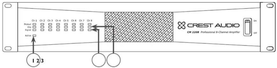
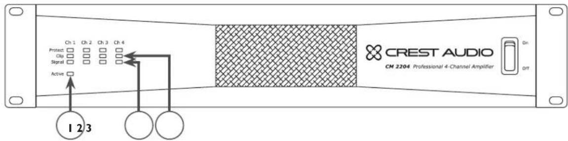
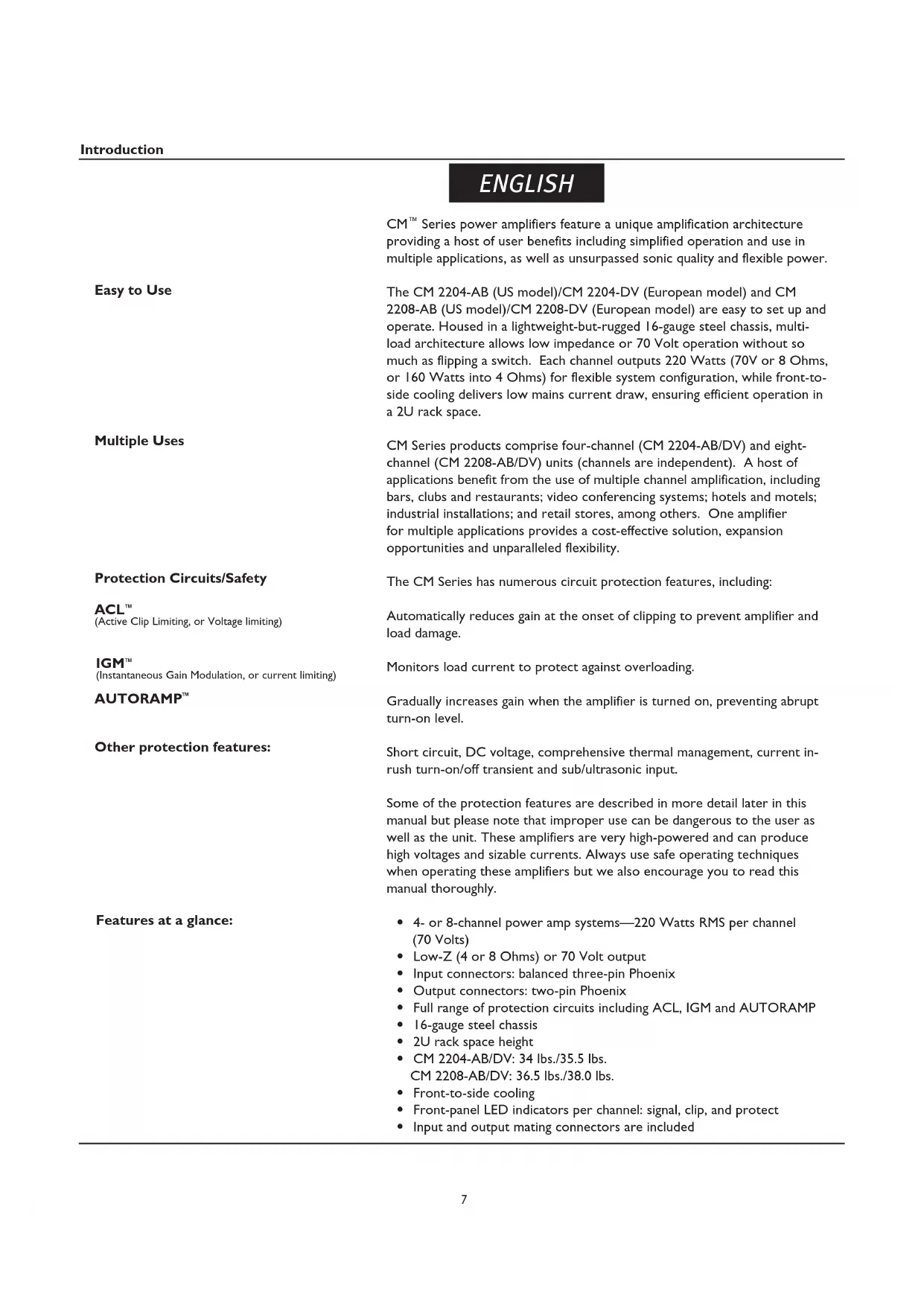
(I) Power Indicator
The green LED indicates that AC power is supplied to the unit and the power switch is ON.
(2) Signal Indicators
Green LEDs indicate significant signal presence on that channel output. The Signal Indicator illuminates only when an output signal is 1 Watt or higher (at 70V). Therefore, it is possible to have an acceptably strong signal without the Signal Indicator illuminating.
(3) Clip Indicators
The Clip Indicator LED illuminates yellow when the CM 2204/CM 2208 experiences excessive voltage or current into the load. When the amplifier output reaches its limits, Active Clip Limiting (ACL ^TM ) will attempt to compress the signal, causing the Clip LED to illuminate momentarily. An over-current condition is more likely to occur with low impedance speakers. For more information on clipping, see the IGM ^TM and ACL descriptions on page 7.
Upon continuous clipping, the unit will go into Protect (see # 4 below) for one second and check the clipping condition. If the unit experiences a persistent clipping condition, the unit will go into Protect permanently for that channel, indicated by the Protect LED blinking steadily. In this case, to bring that channel out of Protect mode, it is necessary to cycle power by turning the unit OFF and then ON. If the Protect LED continues to blink after power is restored, it is likely that the channel is damaged and service to the unit is required.
Upon powering up the unit, the Protect LEDs illuminate momentarily and then turn off one channel at a time and then remain off. During normal operation, an over-current condition can occur if the amplifier is being overdriven to the point where clipping is continuous or from a short circuit in the speaker output. The Protect LED will illuminate red when one of these conditions occurs.
The internal temperature of CM ^™ Series amplifiers is 65° celsius. Should the unit exceed this temperature, the amplifier will go into thermal protect mode (generally, this would only occur if the internal fan fails). If the amplifier has a thermal fault condition, all LEDs will illuminate. When the amplifier cools down, the unit will restart automatically.
(5) AC Power Switch
CM Series power amplifiers have a standard AC switch on the front panel.

Warning: The power switch does not break both sides of the line and under certain conditions hazardous energy can be present when the switch is in the OFF position.
(6) Cooling Air Vent
The CM Series is designed to operate under extreme conditions. The front-panel design features a duct that allows air to be drawn in by the fan, circulated through the removable filter (for cleaning) and finally dispersing out the sides of the unit. The openings on the front and sides of the unit should never be blocked. It is recommended that the removable filter be cleaned with compressed air.
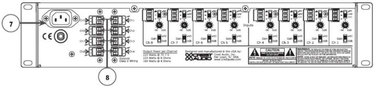
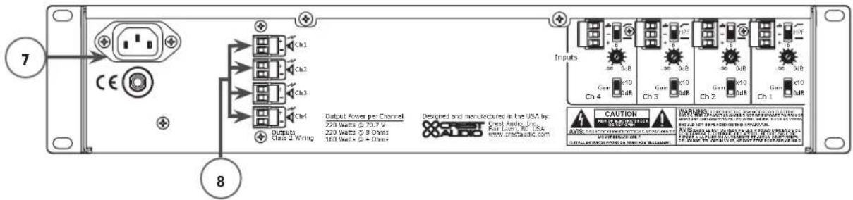
(7) AC Mains Power Receptacle
This is a standard IEC power connector. An AC mains cord having the appropriate AC plug and ratings for the intended operating voltage is included in the carton. The mains cord should be connected to the amplifier before connecting to a suitable AC outlet.

AC Mains Cord

The mains cord supplied with the unit is a heavy duty, three conductor-type with a conventional 120 VAC plug (230 VAC European) with ground pin. Never break off the ground pin on any equipment. It is provided for your safety. If the outlet used does not have a ground pin, a suitable grounding adapter should be used and the third wire should be properly grounded.
NOTE FOR UK ONLY:
If the colors of the wires in the mains lead of this unit do not correspond with the colored markings identifying terminals in your plug, proceed as follows: (1) The wire that is colored green and yellow must be connected to the terminal marked by the letter E, or by the earth symbol, or colored green or green and yellow. (2) The wire that is colored blue must be connected to the terminal that is marked with the letter N, or colored black. (3) The wire that is colored brown must be connected to the terminal that is marked with the letter L or colored red.
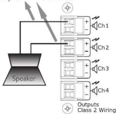
(8) Channel Outputs
The outputs are two-pin Phoenix connectors. Connect the loudspeaker system to the respective positive (+) and ground (-) terminals as indicated on the unit. An exception is when the unit is in Bridged Mode, whereupon a speaker is connected to two positive terminals on the outputs of two channels.
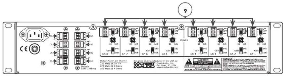
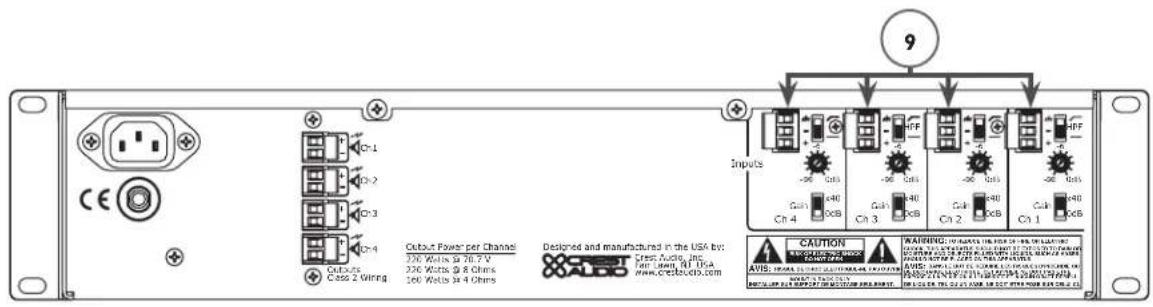
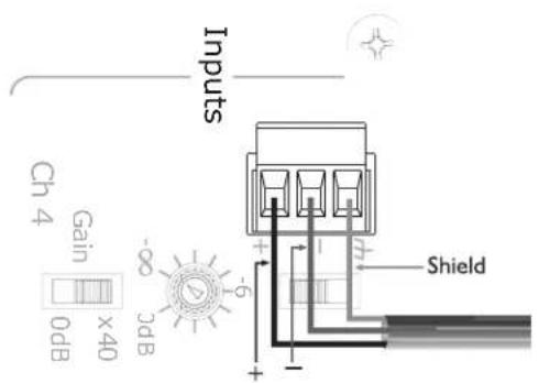
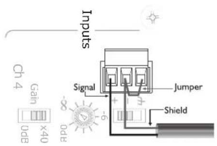
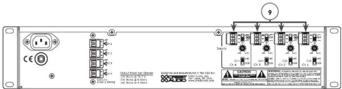
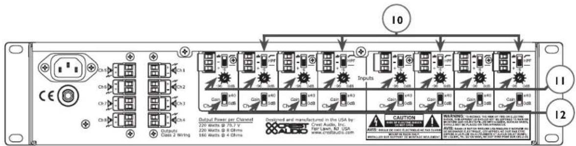
(9) Channel Inputs
The inputs are balanced, three-pin Phoenix connectors. Connect the incoming signals to the respective positive (+), negative (-) and ground ( ) terminals as indicated on the unit. Channel input sensitivity is 0dBu (0.775V) when the 0dB gain setting is selected. This equates to a gain of 90.3x. Gain can also be decreased to x40 with the gain setting switch (see # 12 Gain Select). If using bridged, see the Bridged Mode section.
Input Connections
The Phoenix connectors are wired as: Pin 1 is positive; Pin 2 is negative; and Pin 3 is chassis ground. Normally balanced inputs are wired using two-conductor shielded cable as shown in the following diagram. For unbalanced (single-ended) inputs, the single conductor is wired to Pin 1 and the shield is connected to Pins 2 & 3 as shown in the following diagram.
Balanced Unbalanced

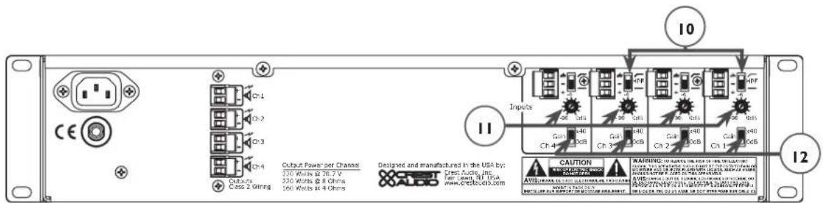
(10) High-Pass Filter
This two-position switch provides enabling or bypass of a high-pass filter, which is available on each channel input. In the top position (enabled), the high-pass filter cutoff is 70 Hz. In the bottom position (disabled), the input frequency range is extended down to 1 Hz. The top and bottom positions of the high-pass filter are indicated on the unit by a sloped line and a flat line, respectively.
(II) Stepped Attenuators
Each channel input features a 21-position stepped attenuator ranging from negative infinity to 0 dB. The "halfway" position of the stepped attenuator is -6 dB, as indicated on the unit.
(12) Gain Select
An individual Gain Select is available on each channel input. This two-position switch can be set at 0 dB in the bottom position and x40 in the top position.
(13) Circuit Breaker

If the circuit breaker pops, turn the unit OFF and let sit for one minute and then turn back ON. If the circuit breaker pops a second time, the unit may be damaged and should be returned to a Crest Audio dealer for servicing.

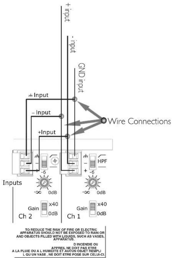
A pair of amplifier channels may be bridged together to make a single output with a power rating equal to the sum of both channel power ratings at twice the load rating of a single channel. In other words, bridging two amplifiers rated for 160 Watts into 4 Ohms will produce 320 Watts into 8 Ohms.
In Bridged Mode, the channels operate at opposite polarity from each other so that one channel pushes and the other pulls equally. This mode sends the input signal to one channel and the same signal with its polarity reversed to the other channel for any two channels (1/2, 3/4 on the CM 2204-AB/DV or 1/3, 2/5, 4/6, 7/8 on the CM 2208-AB/DV). For example, to bridge channels 1 and 2, connect the input signal to the channel 1 input connector using the standard connections (see # 9, Channel Inputs in Back Panel section). On channel 2 however, reverse the positive and negative input connections so that the positive (+) connector is connected channel 2's negative (-) receptacle and the negative input connector (-) is connected to channel 2's positive (+) receptacle.
Both channel level controls (in this example, 1 & 2) MUST be used to control the signal level and both MUST be set at the same position.
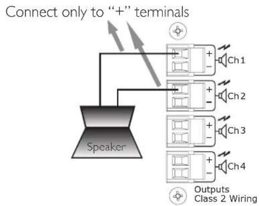
flowchart
graph TD
    Speaker --> Connect["Connect only to “+” terminals"]
    Connect --> Ch1["Ch1"]
    Connect --> Ch2["Ch2"]
    Connect --> Ch3["Ch3"]
    Connect --> Ch4["Ch4"]
    Ch1 --> Outputs["Outputs"]
    Ch2 --> Outputs
    Ch3 --> Outputs
    Ch4 --> Outputs
    Outputs --> Class2["Wiring"]
    Class2 --> Outputs
The loudspeaker load is connected only to the designated positive (+) output terminals of the bridged channels. NEVER ground either side of the loudspeaker load cable when the amplifier is in Bridged Mode as both sides are “hot.” If an output patch panel is used, all connections must be isolated from each other and from the panel. When using the low-Z output, the minimum nominal load impedance in Bridged Mode is 8 Ohms; this is equivalent to driving both bridged channels at 4 Ohms. When using the 70 Volt output, the bridged output is 140 Volts and the minimum load impedance in Bridged Mode is 50 Ohms. Driving loads of lesser impedance may activate the protection circuits. See Output Modes section for more information.

Note: Regardless of operating mode, NEVER connect the amplifier outputs together.
Caution: Output voltages greater than 120 V RMS are available between the bridged terminals. CLASS 3 wiring must be used in accordance with national and local codes to connect the loudspeaker system.

Warning: The loudspeaker output connections of this amplifier are hazardous when live and present a shock hazard when they are energized. Take the following precautions:
- Do not touch any bare wires that are connected to the loudspeaker output connectors.
- Use insulated loudspeaker cables and touch-proof connectors on the loudspeakers.
- Do not attempt to make connections to the output connectors or the loudspeaker connectors when the amplifier is turned ON.
- Double-check all connections and make sure there are no exposed wires or connectors before turning the on amplifier.
- Make sure there are no frayed cables or wires and that all connections are tight and secure every time before turning the amplifier on.
- External wiring connected to these terminals requires installation by a trained person or the use of ready-made leads or cords.
Output Modes
Each channel of the CM ^TM 2204-AB/DV or CM 2208-AB/DV can be used in Direct Drive (Low-Z, 70V or 140V) or Isolated Drive (100V of 50V) applications.
Low-Z
This mode allows each output of the channel pair to drive a 4 or 8 Ohm loudspeaker load. Use Bridged Mode (See Bridged Mode section) to deliver the power of both channels to a single 8 Ohm load such as a subwoofer.
70V
This mode allows each output of the channel pair to directly drive a 70 Volt constant-voltage audio distribution system. Use the Bridged Mode (See Bridged Mode section) to deliver the power of both channels to a 140 Volt constant-voltage audio distribution system.
100V/50V
The output of the CM 2204-AB/DV and CM 2208-AB/DV can be converted to 100V or 50V with the optional CMX4-50/CMX4-100/CMX8-50/CMX8-100 accessories, respectively.
flowchart
graph TD
    A["20 speakers @ 10 Watts each = 200 Watts"] --> B["Ch1"]
    A --> C["Ch2"]
    A --> D["Ch3"]
    A --> E["Ch4"]
    B --> F["70 V Line"]
    C --> G["70 V Line"]
    D --> H["70 V Line"]
    E --> I["70 V Line"]
    F --> J["Output Class 2 Wiring"]
    G --> J
    H --> J
    I --> J
    style A fill:#f9f,stroke:#333
    style B fill:#ccf,stroke:#333
    style C fill:#ccf,stroke:#333
    style D fill:#ccf,stroke:#333
    style E fill:#ccf,stroke:#333
    style F fill:#cfc,stroke:#333
    style G fill:#cfc,stroke:#333
    style H fill:#cfc,stroke:#333
    style I fill:#cfc,stroke:#333
Specification CM
TM 2208 CM 2204
Non-Bridged Mode
Rated Power (one channel driven)
4 Ohms 160 Watts 160 Watts
8 Ohms 240 Watts 245 Watts
70 Volts (24 Ohms) 230 Watts 220 Watts
Rated Power (all channels driven)
4 Ohms 150 Watts 155 Watts
8 Ohms 210 Watts 240 Watts
70 Volts (24 Ohms) 170 Watts 180 Watts
Minimum Load Impedance 4 Ohms 4 Ohms
Bridged Mode
Rated Power (one channel driven)
8 Ohms 320 Watts 320 Watts
140 Volts 460 Watts 440 Watts
Rated Power (all channels driven)
8 Ohms 300 Watts 310 Watts
140 Volts 340 Watts 360 Watts
Minimum Load Impedance 8 Ohms 8 Ohms
Frequency Response (HPF off)
-1 dB @ 1 Watt (8 Ohm Load) 5 Hz–20 kHz 5 Hz–20 kHz
THD @ rated power, 1 kHz (70 V)
<0.02%
<0.02%
Damping Factor (8 Ohms)
200
200
Input CMRR
<-60 dB <-60 dB
Voltage Gain
x40 or 0 dBu (x90)
x40 or 0 dBu (x90)
Input Sensitivity (0 dBu setting)
0.775 V
0.775 V
Input Impedance
20 K Ohms balanced
20 K Ohms balanced
10 K Ohms unbalanced
10 K Ohms unbalanced
Noise and Hum
Below rated output, 22 Hz–22 kHz
-97 dB
-97 dB
Specification CM
TM 2208 CM 2204
Current Consumption (Multiply current by 0.5 for 230 V units)
1/3 power, 70 V output 8.0 A 4.4 A
1/8 power, 70 V output 4.0 A 2.3 A
Idle <2 A <1 A
Thermal Emission
I/8 power, 70 V output 724 BTU/hr 473 BTU/hr
I/3 power, 70 V output 947 BTU/hr 621 BTU/hr
Controls
Front: AC switch
CM 2204, Rear: 4 channel input signal attenuators, 4 channel HPF select switches, 4 channel gain select switches
CM 2208, Rear: 8 channel input signal attenuators, 8 channel HPF select switches, 8 channel gain select switches
Indicator LEDs (front panel)
CM 2204: 4 clip, 4 signal, 4 protect, 1 power
CM 2208: 8 clip, 8 signal, 8 protect, 1 power
Protection
Over-temperature, DC, turn on/off transients, subsonic, short-circuit, over-current
Connectors
CM 2204, Input: Four 3-position Euro-style detachable terminal blocks
CM 2208, Input: Eight 3-position Euro-style detachable terminal blocks
CM 2204, Output: Four 2-position Euro-style detachable terminal blocks
CM 2208, Output: Eight 2-position Euro-style detachable terminal blocks
Construction
16-gauge steel-reinforced with 12-gauge rack ears
Dimensions
Height: 3.50" (8.84 cm); 2 EIA rack spaces
Width, front: 19.00" (48.26 cm)
Width, rear: 17.00" (43.18 cm)
Overall depth: 17.05" (43.31 cm)
Mounting depth: 16.63" (42.24 cm) behind front rack ears
Weight
CM 2204-AB: 34 lbs. (15.4 kg) CM2204-DV: 35.5 lbs. (16.1 kg)
CM 2208-AB: 36.5 lbs. (16.5 kg) CM2208-DV: 38 lbs. (17.2 kg)
Power Requirements
120 VAC 60 Hz (-AB versions)
230 VAC 50 Hz (-DV versions)
Test Conditions
120 VAC 60 Hz Line Input voltage maintained (-AB versions)
230 VAC 50 Hz Line Input voltage maintained (-DV versions)
Support
In the unlikely event that your amplifier develops a problem, it must be returned to an authorized distributor or service center or shipped directly to our factory.
To obtain service, contact your nearest Crest Audio Service Center, Distributor, Dealer or any of the worldwide Crest Audio offices (available online at www.crestaudio.com).
Contact Us
Customer Service phone 201.475.4600 USA email custsrv@crestaudio.com
Technical Support phone 201.475.4600 USA email techserve@crestaudio.com
Web Site www.crestaudio.com
Mail Crest Audio Inc. 16-00 Pollitt Drive Fair Lawn, NJ 07410 USA
DEUTSCH
(9) Kanaleingänge

(10) Hochpassfilter
flowchart
graph TD
    A["20 speakers @ 10 Watts each = 200 Watts"] --> B["Ch1"]
    A --> C["Ch2"]
    A --> D["Ch3"]
    A --> E["Ch4"]
    B --> F["70 V Line"]
    C --> G["70 V Line"]
    D --> H["70 V Line"]
    E --> I["70 V Line"]
    F --> J["Output Class 2 Wiring"]
    G --> J
    H --> J
    I --> J
    J --> K["8 speakers @ 25 Watts each = 200 Watts"]
Spécification CM
TM 2208 CM 2204
Mode Normal
70 Volts (24 Ohms) 230 Watts 220 Watts
8 Ohms 320 Watts 320 Watts
140 Volts 460 Watts 440 Watts
-1 dB @ 1 Watt (Charge de 8 Ohm) 5 Hz–20 kHz 5 Hz–20 kHz
1 kHz (70 V) <0.02% <0.02%
Largeur, facade: 19.00" (48.26 cm)
CM 2204-AB: 34 lbs. (15.4 kg) CM2204-DV: 35.5 lbs. (16.1 kg)
CM 2208-AB: 36.5 lbs. (16.5 kg) CM2208-DV: 38 lbs. (17.2 kg)
Adresse postale Crest Audio Inc. 16-00 Pollitt Drive Fair Lawn, NJ 07410 USA
ESPAÑOL


(10) Filtro Paso-Alto
Connect only to "+" terminals
flowchart
graph TD
    Speaker --> Ch1["Ch1"]
    Speaker --> Ch2["Ch2"]
    Speaker --> Ch3["Ch3"]
    Speaker --> Ch4["Ch4"]
    Ch1 --> Outputs["Outputs Class 2 Wiring"]
    Ch2 --> Outputs
    Ch3 --> Outputs
    Ch4 --> Outputs
flowchart
graph TD
    A["20 speakers @ 10 Watts each = 200 Watts"] --> B["Ch1"]
    A --> C["Ch2"]
    A --> D["Ch3"]
    A --> E["Ch4"]
    B --> F["70 V Line"]
    C --> G["70 V Line"]
    D --> H["70 V Line"]
    E --> I["70 V Line"]
    F --> J["Output Class 2 Wiring"]
    G --> J
    H --> J
    I --> J
    J --> K["8 speakers @ 25 Watts each = 200 Watts"]
Especificaciones CM
TM 2208 CM 2204
Modo Sin Puentear
Frontal: Interruptor AC
CM 2204-AB: 34 lbs. (15.4 kg) CM2204-DV: 35.5 lbs. (16.1 kg)
CM 2208-AB: 36.5 lbs. (16.5 kg) CM2208-DV: 38 lbs. (17.2 kg)
Correo Crest Audio Inc. 16-00 Pollitt Drive Fair Lawn, NJ 07410 USA
CREST AUDIO LIMITED WARRANTY
Effective Date: November 1, 2000
What This Warranty Covers
Your Crest Audio Warranty covers defects in material and workmanship in Crest Audio products purchased and serviced in the U.S.A.
What This Warranty Does Not Cover
The Warranty does not cover: (1) damage caused by accident, misuse, abuse, improper installation or operation, rental, product modification or neglect; (2) damage occurring during shipment; (3) damage caused by repair or service performed by persons not authorized by Crest Audio; (4) products on which the serial number has been altered, defaced or removed; (5) products not purchased directly from Crest Audio or from an Authorized Crest Audio Dealer.
Who This Warranty Protects
This Warranty protects only the original purchaser of the product.
How Long This Warranty Lasts
The Warranty begins on the date of purchase by the original retail purchaser. The duration of the Warranty is as follows:
Product Category Duration
| Amplifiers 5 years | |
| Consoles 5 years | |
| Signal Processing 2 years *(+1 year) | |
| Enclosures 3 years *(+2 years) | |
| “Crest Performance” 2 years *(+2 years) |
[*denotes additional warranty period applicable if optional Warranty Registration Card is completed and returned to Crest Audio by original purchaser within 90 days of purchase.]
[**Denotes all products sold under the "Crest Performance" brand including amplifiers, consoles, signal processing, enclosures and any other product category.]
What Crest Audio Will Do
We will repair or replace (at Crest Audio's discretion) products covered by warranty at no charge for labor or materials. If the product or component must be shipped to Crest Audio for warranty service, the consumer must pay initial shipping charges. If the repairs are covered by warranty, Crest Audio will pay the return shipping charges.
How To Get Warranty Service
(1) Take the defective item and your sales receipt or other proof of date of purchase to your Authorized Crest Audio Dealer or Authorized Crest Audio Service Center. OR
(2) Ship the defective item, prepaid, to Crest Audio, 100 Eisenhower Dr., Paramus, NJ 07652. Include a detailed description of the problem, together with a copy of your sales receipt or other proof of date of purchase as evidence of warranty coverage. Also provide a complete return address.
Limitation of Implied Warranties
ANY IMPLIED WARRANTIES, INCLUDING WARRANTIES OF MERCHANTABILITY AND FITNESS FOR A PARTICULAR PURPOSE, ARE LIMITED IN DURATION TO THE LENGTH OF THIS WARRANTY. Some states do not allow limitations on how long an implied warranty lasts, so the above limitation may not apply to you.
Exclusions of Damages
CREST AUDIO'S LIABILITY FOR ANY DEFECTIVE PRODUCT IS LIMITED TO THE REPAIR OR REPLACEMENT OF THE PRODUCT, AT CREST AUDIO'S OPTION. IF WE ELECT TO REPLACE THE PRODUCT, THE REPLACEMENT MAY BE A RECONDITIONED UNIT. CREST AUDIO SHALL NOT BE LIABLE FOR DAMAGES BASED ON INCONVENIENCE, LOSS OF USE, LOST PROFITS, LOST SAVINGS, DAMAGE TO ANY OTHER EQUIPMENT OR OTHER ITEMS AT THE SITE OF USE, OR ANY OTHER DAMAGES WHETHER INCIDENTAL, CONSEQUENTIAL OR OTHERWISE, EVEN IF CREST AUDIO HAS BEEN ADVISED OF THE POSSIBILITY OF SUCH DAMAGES. Some states do not allow the exclusion or limitation of incidental or consequential damages, so the above limitation or exclusion may not apply to you.
This Warranty gives you specific legal rights, and you may also have other rights which vary from state to state.
If you have any questions about this warranty or service received or if you need assistance in locating an Authorized Service Center, please contact Crest Audio at (201) 909-8700 and ask for the service department.
Features and specifications subject to change without notice.

Features and specifications subject to change without notice.
Crest Audio Inc. • 16-00 Pollitt Drive • Fair Lawn, NJ 07410 USA
TEL: 201.475.4600 · FAX: 201.909.8744 · www.crestaudio.com
80305115