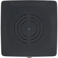
DTI911 - Sensor IFM - Free user manual and instructions
Find the device manual for free DTI911 IFM in PDF.


User questions about DTI911 IFM
0 question about this device. Answer the ones you know or ask your own.
Ask a new question about this device
Download the instructions for your Sensor in PDF format for free! Find your manual DTI911 - IFM and take your electronic device back in hand. On this page are published all the documents necessary for the use of your device. DTI911 by IFM.
USER MANUAL DTI911 IFM
Operating instructions
DTI801
DTI901
DTI911
DTI921
Read/write head
Contents
1 Preliminary note 4
1.1 Symbols used 4
1.2 Warnings.... 4
1.3 Legal and copyright information 4
1.4 Open source information.... 5
2 Safety instructions.... 6
2.1 Safety symbols on the unit 6
2.2 Safety note on high-frequency electromagnetic radiation 6
2.3 Cybersecurity 7
3 Intended use.... 8
3.1 Application area 8
4 Items supplied.... 9
5 Function 10
5.1 Device overview 10
5.2 IO-Link 11
5.2.1 General information.... 11
5.2.2 Device-specific information 11
6 Mounting.... 12
6.1 Installation instructions for devices 12
6.2 Installation instructions for ID tags.... 12
6.3 Avoiding interference 12
6.4 Mounting options.... 13
6.4.1 Installation with angle bracket E80335 13
6.4.2 Installation with mounting device E80336 13
6.4.3 Installation with fixing bars E80337 14
6.5 Mounting distances.... 14
6.6 Positioning of the ID tags 15
7 Electrical connection.... 16
7.1 Wiring 16
7.2 Connecting the functional earth.... 16
8 Operating and display elements 17
9 Operation 18
9.1 Status bits.... 18
9.2 Operating mode "SINGLE EPC.... 19
9.3 Operating Mode "READ DATA AUTO" 20
9.4 Operating Mode "WRITE DATA AUTO" 21
9.5 Operating mode "EPC REPORT.... 23
9.5.1 Example "EPC REPORT" 24
9.6 Operating mode "EPC LIST 25
9.6.1 Example "EPC LIST" 26
9.7 Operating mode "WRITE EPC" 26
9.7.1 Example "WRITE EPC" 28
9.7.2 Example "WRITE EPC not executed" 28
9.8 Operating mode "READ DATA 29
9.8.1 Example "READ DATA" 30
9.8.2 Example "READ DATA not executed" 31
9.9 Operating mode "WRITE DATA" 32
9.9.1 Example "WRITE DATA" 33
9.9.2 Example "WRITE DATA not executed" 34
9.10 Operating mode "LOCK DATA" 35
9.11 Error values when executing commands.... 36
9.12 Device-specific parameters 37
9.12.1 Parameter "Data Hold Time" 37
9.12.2 Parameter "Auto-Read/Write Address" 37
9.12.3 Parameter "Auto-Read/Write
Data Length" 37
9.12.4 Parameter "ID Tag Memory Area for Auto-Read/Write" 38
9.12.5 Parameter "ID Tag Access Password" 38
9.12.6 Parameter "ID Tag Selection Target 38
9.12.7 Parameter "ID Tag Selection Mask" 38
9.12.8 Parameter "ID Tag Selection Start Bit" 39
9.12.9 Parameter "ID Tag Selection Length" 39
9.12.10 Parameter "RSSI Filter Lowest Value" 39
9.12.11 Parameter "RSSI Filter Highest Value" 39
9.12.12 Parameter "Activate RSSI Filter" 39
9.12.13 Parameter "Antenna Output Power for Read Access" 39
9.12.14 Parameter "Antenna Output Power for Write Access" 40
9.12.15 Parameter "ID Tag Detection Mode" 40
9.13 ID tag 40
9.13.1 ID tag detection.... 40
9.13.2 ID tag selection 41
9.13.3 RSSI filter 42
9.13.4 Reading and writing ID tag data 42
9.13.5 Write protecting the ID tag. 43
10 Maintenance, repair and disposal 44
11 Approvals / standards 45
Glossary 46
1 Preliminary note
You will find instructions, technical data, approvals and further information using the QR code on the unit / packaging or at documentation.ifm.com.
1.1 Symbols used
√ Requirement
Instructions
Reaction, result
[...] Designation of keys, buttons or indications
→ Cross-reference

Important note
Non-compliance may result in malfunction or interference.

Information
Supplementary note
1.2 Warnings
Warnings indicate the possibility of personal injury and damage to property. This enables safe product handling. Warnings are graded as follows:

WARNING
Warning of serious personal injury
▷ If the warning is not observed, fatal and serious injuries are possible.

CAUTION
Warning of minor to moderate personal injury
▷ If the warning is not observed, minor to moderate injuries are possible.
ATTENTION
Warning of damage to property
▷ If the warning is not observed, damage to property is possible.
1.3 Legal and copyright information
© All rights reserved by ifm electronic gmbh. No part of these instructions may be reproduced and used without the consent of ifm electronic gmbh.
All product names, pictures, companies or other brands used on our pages are the property of the respective rights owners.
• AS-i is the property of AS-International Association, (→ www.as-interface.net)
• CAN is the property of Robert Bosch GmbH, Germany ( → www.bosch.de)
• CAN is the property of CiA (CAN in Automation e. V.), Germany ( → www.can-cia.org)
- CODESYS™ is the property of CODESYS GmbH, Germany (→ www.codesys.com)
- Device
Net™ is the property of ODVA™ (Open Device
Net Vendor Association), USA (→ www.odva.org)
- Ether
Net/IP® is the property of → ODVA™ - EtherCAT® is a registered trademark and patented technology, licensed by Beckhoff Automation GmbH, Germany.
- IO-Link® is the property of PROFIBUS Nutzerorganisation e. V., Germany (→ www.io-link.com)
- ISOBUS is the property of AEF - Agricultural Industry Electronics Foundation e. V., Germany (→ www.aef-online.org)
- Microsoft® is the property of Microsoft Corporation, USA (→ www.microsoft.com)
- Modbus® is the property of Schneider Electric SE, France (→ www.schneider-electric.com)
- PROFIBUS® is the property of PROFIBUS Nutzerorganisation e. V., Germany (→ www.profibus.com)
• PROFINET® is the property of → PROFIBUS Nutzerorganisation e. V., Deutschland - Windows® is the property of → Microsoft Corporation, USA
1.4 Open source information
i
For more open source information see: documentation.ifm.com.
2 Safety instructions
- The unit described is a subcomponent for integration into a system.
- The system architect is responsible for the safety of the system.
-
The system architect undertakes to perform a risk assessment and to create documentation in accordance with legal and normative requirements to be provided to the operator and user of the system. This documentation must contain all necessary information and safety instructions for the operator, the user and, if applicable, for any service personnel authorised by the architect of the system.
-
Read this document before setting up the product and keep it during the entire service life.
- The product must be suitable for the corresponding applications and environmental conditions without any restrictions.
- Only use the product for its intended purpose (→ Intended use).
- If the operating instructions or the technical data are not adhered to, personal injury and/or damage to property may occur.
- The manufacturer assumes no liability or warranty for any consequences caused by tampering with the product or incorrect use by the operator.
- Installation, electrical connection, set-up, operation and maintenance of the product must be carried out by qualified personnel authorised by the machine operator.
- Protect units and cables against damage.
• Store the product in its original packaging.
2.1 Safety symbols on the unit
The following symbols are used on the device. Observe the instructions in order to avoid hazards:


• Electric supply must correspond to IEC 61010-1, chapter 9.4 - Limited-energy circuit.
• Device of protection class III. Only for operation in SELV/PELV circuits.
2.2 Safety note on high-frequency electromagnetic radiation
Under application-specific conditions, the risk for the user may differ depending on the installation situation and the device settings.
The system architect/operator is required to carry out a hazard analysis and to take appropriate measures for the protection of persons. In particular national regulations also have to be adhered to. Possible protective measures may include guaranteed minimum distances of a user, access controls and user training.

WARNING
Operation of this device can cause radio interference in residential areas.
▷ The device emits high-frequency electromagnetic waves that may interfere with the operation of electronic devices in the vicinity, including pacemakers, hearing aids and defibrillators.
▶ Due to human exposure regulations, a minimum distance of 20 cm must be maintained between the device and persons.
▶ If you have a pacemaker or other implanted medical product, do not use the device without first consulting your doctor or the manufacturer of your medical product. Keep a safe distance between the device and your medical devices and refrain from further use of the device if you observe permanent impairment of your medical product.
2.3 Cybersecurity
Installation
The device is suitable for operation in a secure environment according to IEC 62443-1-1.
The device was designed for operation behind a firewall.
▶ Carry out a risk assessment of the system according to IEC 62443-1-1.
▶ Take measures to ensure physical security.
Operation
▶ Observe the security functions described in the product documentation and the recommendations for their use.
Maintenance
- ▶ Back up system configuration and system data in accordance with your company’s change management processes.
Decommissioning
▶ Ensure that no sensitive information can fall into unauthorised hands.
▶ Always reset the system settings to the factory settings before decommissioning the device.
3 Intended use
The read/write head reads and writes ID tags without contact.
The data is made available as process data via the IO-Link interface.
3.1 Application area
The device safety is rated for use under the following operating conditions:
- Protection class 3 (SELV/PELV) and supply of the device to limited energy according to IEC 61010-1, chapter 9.4. Isolate the external circuits as required by figure 102 in IEC 61010-2-201.
- For indoor use.
• Altitudes up to 2000 m. - Relative air humidity up to max. 80 %, non condensing.
- Pollution degree 2.
4 Items supplied
- RFID compact unit
• Package insert 'general information'
• Package insert 'radio approval'

The device is supplied without installation and connection accessories.
Available accessories: www.ifm.com.
The optimum function is not ensured when using components from other manufacturers.
5 Function
The ID tags are operated passively without battery. The energy required for operation is provided by the compact RFID device.
The energy is transferred via an electromagnetic wave. The receiving antenna takes up the wave and transforms it into voltage which supplies the data carrier with energy.
The radiated power is specified in ERP (Effective Radiated Power) and in EIRP (Effective Isotropic Radiated Power) for the devices. The respective value can be converted using the following formula:
P [dBm EIRP] = P [dBm ERP] + 2.15 [dB]
5.1 Device overview
DTI801
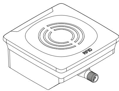 | Article number: | DTI801 |
| Function: | RFID compact device | |
| Type designation: | DTRUHFE HLRWIOUS04 | |
| Type: | rectangular | |
| Operating frequency: | 865-868 MHz | |
| Typical transmitter power: | 22.5 dBm ERP (178 mW) |
DTI901
 | Article number: | DTI901 |
| Function: | RFID compact device | |
| Type designation: | DTRUHFA HLRWIOUS04 | |
| Type: | rectangular | |
| Operating frequency: | 902-928 MHz | |
| Typical transmitter power: | 25.2 dBm EIRP (331 mW) |
DTI911
 | Article number: | DTI911 |
| Function: | RFID compact device | |
| Type designation: | DTRUHFA HLRWPNUS04 | |
| Type: | rectangular | |
| Operating frequency: | 920-925 MHz | |
| Typical transmitter power: | 25.2 dBm EIRP (331 mW) |
DTI921
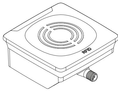 | Article number: | DTI921 |
| Function: | RFID compact device | |
| Type designation: | DTRUHFA HLRWIOUS04 | |
| Type: | rectangular | |
| Operating frequency: | 920.25-925.75 MHz | |
| Typical transmitter power: | 25.2 dBm EIRP (331 mW) |
5.2 IO-Link
5.2.1 General information
This device has an IO-Link interface which enables direct access to process and diagnostic data. It is also possible to set the parameters of the device while it is in operation. Operation of the device via the IO-Link interface requires an IO-Link capable module (IO-Link master).
5.2.2 Device-specific information
With a PC, IO-Link software and an IO-Link adapter cable communication is possible when the system is not in operation.

Necessary information about the IODD, process data structure, diagnostic information, parameter addresses and the required hardware and software can be found at www.ifm.com.
6 Mounting
ATTENTION
Radiated electromagnetic field strengths
▷ The device sends ultrahigh frequency electromagnetic waves. It complies with the country-specific limit values for the public and workers.
▶ Disconnect the device in the vicinity of medical equipment.
6.1 Installation instructions for devices
Devices installed next to each other interfere if they are not configured correspondingly.
When mounting several RFID units adhere to the minimum distances between the systems.
Installing a unit in or on metal reduces the read and write distance.
Device performance can be affected if positioned in the immediate vicinity of powerful HF emission sources such as welding transformers or converters.
6.2 Installation instructions for ID tags
For installation in and on metal use the ID tags provided for this purpose.
Position the ID tag in the area of the sensing face. When doing so, the angle of aperture and the operating distance must be adhered to ( → Data sheet of the device).
Align the axes of the RFID device and the ID-TAG in the same way.
6.3 Avoiding interference
The device generates a modulated electromagnetic field in the following frequency ranges:
DTI801: 865-868 MHz
DTI901: 902-928 MHz
DTI911: 920-925 MHz
DTI921: 920.25-925.75 MHz
Interference in data communication is avoided if there are no other RFID UHF devices in the vicinity. If there are other RFID UHF devices in the vicinity:
▶ The mounting distances between the devices should be as large as possible. (→ Mounting distances ☐ 14)
▶ Use the RSSI filter. (→ Parameter "Activate RSSI Filter" ☐ 39)
▶ Use the devices in alternating operation.
▶ Switch the HF field of the device on/off.
The UHF field is attenuated if there are people or objects (cables, metal profiles, etc.) between the device and ID tag.
▶ Keep the area between the device and ID tag clear during reading or writing.
6.4 Mounting options
The device can be mounted without the accessories.
▶ For installation, please use the threaded sleeves on the back of the device.
▷ The required screws are not supplied with the device.
6.4.1 Installation with angle bracket E80335


6.4.2 Installation with mounting device E80336
The mounting device is used to mount the unit on a clamp. Compatible clamps:
• E21110 with a rod diameter of 12 mm
• E20795 with a rod diameter of 14 mm
• E21109 with a rod diameter of 14 mm
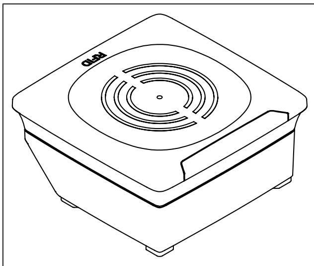

6.4.3 Installation with fixing bars E80337

6.5 Mounting distances
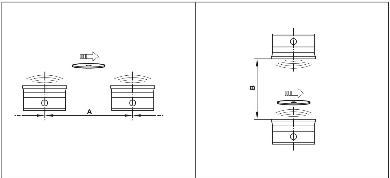
| Operating mode | Distance side (A) | Distance front (B) |
| Reading and writing at 100% transmitting power (simultaneous operation) | >0.6 m | >0.6 m |
| Reading and writing at 100% transmitting power (alternating operation) | >0.3 m | >0.3 m |

Interference in data communication is avoided if there are no other RFID UHF devices in the vicinity. If there are other RFID UHF devices in the vicinity:
▶ The mounting distances between the devices should be as large as possible.
▶ Use the RSSI filter. (→ Parameter "Activate RSSI Filter" ☐ 39)
▶ Use the devices in alternating operation.
▶ Switch the HF field of the device on/off.
6.6 Positioning of the ID tags

Fig. 1: Position the ID tag
▶ Align the ID tag on the antenna central axis.
The distance "D" is indicated in the data sheet.

ID tags are also detected on the back of the device. To avoid this:
▶ Use the RSSI filter. (→ RSSI filter ☐ 42)
7 Electrical connection

The device must be connected by a qualified electrician.
Device of protection class III (PC III).
The electrical supply must only be made via PELV/SELV circuits.
▶ Disconnect power before connecting the device.
ATTENTION
The IP rating indicated in the data sheet is only guaranteed if the M12 connectors are firmly screwed. The device can be damaged by insufficiently tightened M12 connectors.
▶ Screw the M12 connector to the device applying 1 to 1.5 Nm.
7.1 Wiring
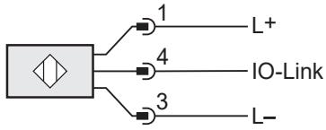
▶ Connect the device to an IO-Link master using a M12 connection cable.
▷ Voltage is supplied via the IO-Link master.
| Pin assignment | Wiring |
 |  |
7.2 Connecting the functional earth

For trouble-free operation:
▶ Connect the device to an earth potential free from external voltage.
▶ Connect the mounting plate to functional earth.
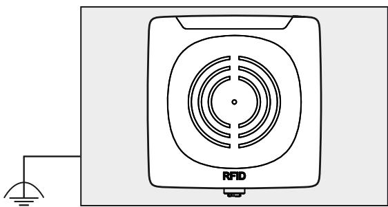
Fig. 2: Mounting plate with mounted device
When the device is mounted on a mounting plate:
▶ Connect one of the 4 mounting bolts on the back of the device to the mounting plate.
▶ Connect the mounting plate to an earth potential free from external voltage.
8 Operating and display elements
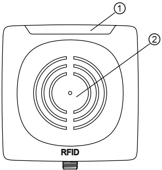
Fig. 3: Operating and display elements
1 LEDs
2 Sensing face
| State | Power LED (green) | ID tag LEDs (yellow/orange) | Fault LED (red) |
| Ready for operation without ID tag | On | Off | Off |
| Ready for operation with ID tag(s) | On | ID tag number 1-4 | Off |
| Inactive | Flashes at 1 Hz | Off | Off |
| Error: Overflow of the ID tag data | On | ID tag number 1-4 | On |
9 Operation
| Command value | Operating mode | Description |
| 0x00 | SINGLE EPC | Read and provide an EPC |
| 0x01 | READ DATA AUTO | Auto-read data |
| 0x02 | WRITE DATA AUTO | Auto-write data |
| 0x03 | EPC REPORT | Create an EPC report |
| 0x04 | EPC LIST | Create an EPC list |
| 0x05 | WRITE EPC | Write EPC |
| 0x06 | READ DATA | Read data |
| 0x07 | WRITE DATA | Write data |
| 0x08 | LOCK DATA | Lock data |
All operating modes use the same status bits and error values in the process images.
In addition to the operating modes the internal antenna of the device can be deactivated. If the antenna is deactivated, the device can still be addressed via IO-Link, but the device no longer generates a high-frequency signal. ID tags are not detected by the device. By deactivating the antenna, interference between devices installed next to each other can be avoided.
The device is activated and deactivated via the bit" Antenna deactivate" in the process data output image. The status of the antenna is read via the bit "Antenna deactivated" in the process data input image.
9.1 Status bits
| Process input | ||||||||
| Bit | 7 | 6 | 5 | 4 | 3 | 2 | 1 | 0 |
| Name | Tag Over-flow | Buffer Over-flow | Antenna de-activated | Tag present | Cmd End | Cmd Start Acknowledge | ||
| Process output | ||||||||
| Bit | 7 | 6 | 5 | 4 | 3 | 2 | 1 | 0 |
| Name | Cmd Antenna deactivate | Cmd Start | ||||||
| Status bit | Value | Description |
| Tag Overflow | 0 | ID tag processing OK |
| 1 | More ID tags are detected than can be processed | |
| Buffer Overflow | 0 | Data transmission OK |
| 1 | Data cannot be transmitted fast enough via IO-Link (only in operating mode “EPC REPORT”) | |
| Antenna deactivated | 0 | Antenna activated, device ready to receive |
| 1 | Antenna deactivated, device not ready to receive | |
| Tag present | 0 | No ID tag in the range of the device |
| 1 | ID tag detected | |
| Cmd End | 0 | Read/write operation not started or active |
| 1 | Read/write operation terminated | |
| Cmd Start Acknowledge | 0 | Start of a read/write operation not acknowledged |
| 1 | Start of a read/write operation acknowledged | |
| Cmd Antenna deactivate | 0 | Activate antenna |
| 1 | Deactivate antenna | |
| Cmd Start | 0 | Reset trigger for read/write operation |
| 1 | Set trigger for read/write operation |
9.2 Operating mode "SINGLE EPC
In the operating mode “SINGLE EPC”, the EPC of an ID tag is read and provided by the device in the process data input. If several ID tags are in the detection zone of the device at the same time, the ID tag with the strongest reception signal (RSSI) is read. If there is no ID tag in the detection zone, the value “0x00” is read. The RSSI byte outputs the current reception signal.

The RSSI value is a signed integer value. For example, "0xD6" corresponds to the RSSI value "-42 dBm".
A maximum of 16 bytes are read for an EPC. If the EPC stored on the ID tag is longer, the remaining bytes are truncated. If the EPC is shorter, the remaining bytes are filled with "0x00". The current length of the EPC is output in the "Length of EPC" field.
When a new ID tag is detected, the device increments the block counter.

The block counter counts up to "255" and then starts again at "0".
The operating mode “SINGLE EPC” is the default operating mode after the device has been started.

The operating mode does not use the following status bits ( → Status bits ☐ 18):
- Cmd Start
- Cmd Start Acknowledge
- Cmd End
| Byte | Process data output | Process data input |
| 0 | Command value = 0x00 | Command value = 0x00 |
| 1 | Status | Status |
| 2 | ignored | RSSI |
| 3 | ignored | Length of EPC |
| 4 | ignored | EPC 0 |
| 5 | ignored | EPC 1 |
| 6 | ignored | EPC 2 |
| 7 | ignored | EPC 3 |
| 8 | ignored | EPC 4 |
| 9 | ignored | EPC 5 |
| 10 | ignored | EPC 6 |
| 11 | ignored | EPC 7 |
| 12 | ignored | EPC 8 |
| 13 | ignored | EPC 9 |
| 14 | ignored | EPC 10 |
| 15 | ignored | EPC 11 |
| 16 | ignored | EPC 12 |
| 17 | ignored | EPC 13 |
| 18 | ignored | EPC 14 |
| 19 | ignored | EPC 15 |
| 20 | ignored | 0x00 |
| 21 | ignored | 0x00 |
| 22 | ignored | 0x00 |
| 23 | ignored | 0x00 |
| 24 | ignored | 0x00 |
| 25 | ignored | 0x00 |
| 26 | ignored | 0x00 |
| 27 | ignored | 0x00 |
| 28 | ignored | 0x00 |
| 29 | ignored | 0x00 |
| 30 | ignored | Block counter |
| 31 | ignored | Error value |
9.3 Operating Mode "READ DATA AUTO"
In the operating mode “READ DATA AUTO” the bytes 0 to 27 represent the data in the memory area of the ID tag.
The memory area is set by the following parameters:
• "Auto-Read/Write Address",
• "Auto-Read/Write Data Length" and
• "Auto-Read/Write Memory Bank".
For memory areas with a data length of < 28 bytes the data remaining in the process image is filled with the value "0x00".
The data in the process image is updated as soon as an ID tag is in the detection zone. The data in the process image is valid as soon as the status bit "Cmd End" is set.
If the ID tag leaves the detection zone, the data bytes remain constant in the process image in accordance with the data hold time. After the data hold time has elapsed, the data bytes in the process data input image are reset to "0x00". If the ID tag remains in the detection zone, the re-reading of the data is triggered by setting the "Cmd Start" bit.
Whenever the data is updated, the block counter is incremented.
If reading was unsuccessful, an error value is shown in the process image.

In the operating mode "READ DATA AUTO", the EPC of an ID tag is not transmitted. The ID tag must be assigned based on the data.

The smaller the set data length, the less time the device needs to perform an operation. As a result, the ID tag's dwell time in the detection zone is shorter.
| Byte | Process data output | Process data input |
| 0 | Command value = 0x01 | Command value = 0x01 |
| 1 | Status | Status |
| 2 | Ignored | Data 0 |
| 3 | Ignored | Data 1 |
| 4 | Ignored | Data 2 |
| 5 | Ignored | Data 3 |
| 6 | Ignored | Data 4 |
| 7 | Ignored | Data 5 |
| 8 | Ignored | Data 6 |
| 9 | Ignored | Data 7 |
| 10 | Ignored | Data 8 |
| 11 | Ignored | Data 9 |
| 12 | Ignored | Data 10 |
| 13 | Ignored | Data 11 |
| 14 | Ignored | Data 12 |
| 15 | Ignored | Data 13 |
| 16 | Ignored | Data 14 |
| 17 | Ignored | Data 15 |
| 18 | Ignored | Data 16 |
| 19 | Ignored | Data 17 |
| 20 | Ignored | Data 18 |
| 21 | Ignored | Data 19 |
| 22 | Ignored | Data 20 |
| 23 | Ignored | Data 21 |
| 24 | Ignored | Data 22 |
| 25 | Ignored | Data 23 |
| 26 | Ignored | Data 24 |
| 27 | Ignored | Data 25 |
| 28 | Ignored | Data 26 |
| 29 | Ignored | Data 27 |
| 30 | Ignored | Block counter |
| 31 | Ignored | Error value |
9.4 Operating Mode "WRITE DATA AUTO"
In the “WRITE DATA AUTO” operating mode the data to be written is defined by the process data output image. If an ID tag enters the detection range, the data bytes are written to the ID tag with the address and length.
The memory area is set by the following parameters:
• "Auto-Read/Write Address",
• "Auto-Read/Write Data Length" and
• "Auto-Read/Write Memory Bank".
Max. 28 bytes can be defined in the process data output image (data 0 to 27). If a shorter length is defined in the parameter "Auto-Read/Write Data Length", the other data bytes are ignored and not written to the ID tag. The write command is started with the status bit "Cmd Start".
If writing was successful, the written data is mirrored in the process data input image, the block counter is increased and the status bit "Cmd End" is set.
If the ID tag leaves the detection zone, the data bytes remain constant in the process image in accordance with the data hold time. After the data hold time has elapsed and when the ID tag leaves the detection zone, the data bytes in the process data input image are reset to "0x00". If the ID tag remains in the detection zone, the re-writing of the data is triggered by setting the status bit "Cmd Start".

If the bytes to be written already exist on the ID tag, the write command is not executed and not acknowledged.

In the operating mode “WRITE DATA AUTO”, writing is executed on all detected ID tags, independently of the EPC. The ID tag selection ( → ID tag selection ☐ 41) and RSSI filter ( → RSSI filter ☐ 42) functions are used for selection.

Under adverse conditions, write operations are repeated. The block counter then does not correspond to the number of ID tags in the detection range.

The smaller the set data length, the less time the device needs to perform an operation. As a result, the ID tag's dwell time in the detection zone is shorter.
| Byte | Process data output | Process data input |
| 0 | Command value = 0x02 | Command value = 0x02 |
| 1 | Status | Status |
| 2 | Data 0 | Data 0 |
| 3 | Data 1 | Data 1 |
| 4 | Data 2 | Data 2 |
| 5 | Data 3 | Data 3 |
| 6 | Data 4 | Data 4 |
| 7 | Data 5 | Data 5 |
| 8 | Data 6 | Data 6 |
| 9 | Data 7 | Data 7 |
| 10 | Data 8 | Data 8 |
| 11 | Data 9 | Data 9 |
| 12 | Data 10 | Data 10 |
| 13 | Data 11 | Data 11 |
| 14 | Data 12 | Data 12 |
| 15 | Data 13 | Data 13 |
| 16 | Data 14 | Data 14 |
| 17 | Data 15 | Data 15 |
| 18 | Data 16 | Data 16 |
| 19 | Data 17 | Data 17 |
| 20 | Data 18 | Data 18 |
| 21 | Data 19 | Data 19 |
| 22 | Data 20 | Data 20 |
| 23 | Data 21 | Data 21 |
| 24 | Data 22 | Data 22 |
| 25 | Data 23 | Data 23 |
| 26 | Data 24 | Data 24 |
| 27 | Data 25 | Data 25 |
| 28 | Data 26 | Data 26 |
| 29 | Data 27 | Data 27 |
| 30 | Block counter | Block counter |
| 31 | ignored | Error value |
9.5 Operating mode "EPC REPORT
In the operating mode "EPC REPORT", the device generates a message when an ID tag enters (arrival = 1) or leaves (arrival = 0) the detection field of the device. With each new message
• the EPC of the ID tag is output,
• the received signal strength (RSSI) is output and
• the block counter is incremented.
The message is transmitted as a process value until the controller confirms the block counter. The controller confirms the block counter by mirroring the block counter value in the output image. If there is no confirmation, the message is automatically confirmed after the data hold time has expired and the new message is transmitted.

The rapid changing of ID tags generates many messages in a short time. If these messages are transmitted too slowly, the result will be a "buffer overflow". This is indicated by the corresponding bit in the status byte.
▶ Confirm the controller actively by mirroring the block counter.
▷ As a result, messages that are not transmitted fast enough are retained.

The RSSI value is a signed integer value. For example, "0xD6" corresponds to the RSSI value "-42 dBm".

The operating mode does not use the following status bits ( → Status bits ☐ 18):
- Cmd Start
- Cmd Start Acknowledge
- Cmd End
| Byte | Process data output | Process data input |
| 0 | command value = 0x03 | command value = 0x03 |
| 1 | Status | Status |
| 2 | ignored | RSSI |
| 3 | ignored | length of EPC |
| 4 | ignored | EPC 0 |
| 5 | ignored | EPC 1 |
| 6 | ignored | EPC 2 |
| 7 | ignored | EPC 3 |
| 8 | ignored | EPC 4 |
| 9 | ignored | EPC 5 |
| 10 | ignored | EPC 6 |
| 11 | ignored | EPC 7 |
| 12 | ignored | EPC 8 |
| 13 | ignored | EPC 9 |
| 14 | ignored | EPC 10 |
| 15 | ignored | EPC 11 |
| 16 | ignored | EPC 12 |
| 17 | ignored | EPC 13 |
| 18 | ignored | EPC 14 |
| 19 | ignored | EPC 15 |
| 20 | ignored | 0x00 |
| 21 | ignored | 0x00 |
| 22 | ignored | 0x00 |
| 23 | ignored | 0x00 |
| 24 | ignored | 0x00 |
| 25 | ignored | 0x00 |
| 26 | ignored | 0x00 |
| 27 | ignored | 0x00 |
| 28 | ignored | 0x00 |
| 29 | ignored | arrival |
| 30 | block counter | block counter |
| 31 | ignored | error value |
9.5.1 Example "EPC REPORT"
The example demonstrates the generation of a message when an ID tag enters (arrival = 1) or leaves (arrival = 0) the detection field of the device.
| Command value | Block counter | Status bit “Cmd Start” | Command value | Data 0 to 27 | ID tag refers to detection field (arrival=1) | Block counter | Error value | Status bit “Cmd End” | Status bit “Cmd Start” | |
| Process data output image | Process data input image | |||||||||
| Preset command | 0x00 | 0x00 | 0 | 0x00 | Single EPC | 0x00 | 0x00 | 0x00 | 0 | 0 |
| Controller sets command (Output EPC report) | 0x03 | 0x00 | 1 | 0x00 | Single EPC | 0x00 | 0x00 | 0x00 | 0 | 0 |
| Device sends EPC2 code “coming” | 0x03 | 0x00 | 1 | 0x03 | EPC2 | 0x01 | 0x01 | 0x00 | 0 | 1 |
| Controller acknowledges receipt of the data | 0x03 | 0x01 | 1 | 0x03 | EPC2 | 0x01 | 0x01 | 0x00 | 0 | 1 |
| Device sends EPC1 code “leaving” | 0x03 | 0x01 | 1 | 0x03 | EPC1 | 0x00 | 0x02 | 0x00 | 0 | 1 |
| Controller acknowledges receipt of the data | 0x03 | 0x02 | 1 | 0x03 | EPC1 | 0x00 | 0x02 | 0x00 | 0 | 1 |
| Device has no further messages | 0x03 | 0x02 | 1 | 0x03 | EPC1 | 0x00 | 0x02 | 0x00 | 0 | 1 |
| Controller withdraws command value | 0x00 | 0x00 | 0 | 0x03 | EPC1 | 0x00 | 0x02 | 0x00 | 0 | 1 |
| Device carries out preset command | 0x00 | 0x00 | 0 | 0x00 | Single EPC | 0x00 | 0x00 | 0x00 | 0 | 0 |
9.6 Operating mode "EPC LIST
In the operating mode "EPC LIST", a list with all ID tags in the detection field is generated by setting the Cmd start bit. The number of detected ID tags is displayed in the field "Total Number of Tags". A process image with the following content is created for each ID tag:
- the RSSI value,
• the length of the EPC and - the EPC.
The block counter indicates the current ID tag in the list. By incrementing the block counter in the process data output image, the controller switches to the next ID tag. As confirmation, the value of the block counter is mirrored by the device.
After all ID tags of the list have been transmitted, a new list is created by setting the Cmd start bit again.

The list is a snapshot and will only be updated by setting the Cmd start bit again.

The RSSI value is a signed integer value. For example, "0xD6" corresponds to the RSSI value "-42 dBm".
| Byte | Process data output | Process data input |
| 0 | command value = 0x04 | command value = 0x04 |
| 1 | status | status |
| 2 | ignored | RSSI |
| 3 | ignored | length of EPC |
| 4 | ignored | EPC 0 |
| 5 | ignored | EPC 1 |
| 6 | ignored | EPC 2 |
| 7 | ignored | EPC 3 |
| 8 | ignored | EPC 4 |
| 9 | ignored | EPC 5 |
| 10 | ignored | EPC 6 |
| 11 | ignored | EPC 7 |
| 12 | ignored | EPC 8 |
| 13 | ignored | EPC 9 |
| 14 | ignored | EPC 10 |
| 15 | ignored | EPC 11 |
| 16 | ignored | EPC 12 |
| 17 | ignored | EPC 13 |
| 18 | ignored | EPC 14 |
| 19 | ignored | EPC 15 |
| 20 | ignored | 0x00 |
| 21 | ignored | 0x00 |
| 22 | ignored | 0x00 |
| 23 | ignored | 0x00 |
| 24 | ignored | 0x00 |
| 25 | ignored | 0x00 |
| 26 | ignored | 0x00 |
| 27 | ignored | 0x00 |
| 28 | ignored | 0x00 |
| 29 | ignored | total number of tags |
| 30 | block counter | block counter |
| 31 | ignored | error value |
9.6.1 Example "EPC LIST"
The example creates a list with all ID tags in the detection field.
| Command value | Block counter | Status bit "Cmd Start" | Command value | Data 0 to 27 | Block counter | Error value | Status bit "Cmd End" | Status bit "Cmd Start" | |
| Process data output image | Process data input image | ||||||||
| Preset command | 0x00 | 0x00 | 0 | 0x00 | Single EPC | 0x00 | 0x00 | 0 | 0 |
| Controller sets command (output EPC list) | 0x04 | 0x00 | 1 | 0x00 | Single EPC | 0x00 | 0x00 | 0 | 0 |
| Device acknowledges command and creates EPC list | 0x04 | 0x00 | 1 | 0x04 | 0x00 | 0x00 | 0x00 | 0 | 1 |
| Device sends first EPC code | 0x04 | 0x00 | 1 | 0x04 | EPC1 | 0x01 | 0x00 | 0 | 1 |
| Controller acknowledges receipt of the data | 0x04 | 0x01 | 1 | 0x04 | EPC1 | 0x01 | 0x00 | 0 | 1 |
| Device sends more EPC codes and ends command | 0x04 | 0x01 | 1 | 0x04 | EPC2 | 0x02 | 0x00 | 1 | 1 |
| Controller acknowledges receipt of the data | 0x04 | 0x02 | 1 | 0x04 | EPC2 | 0x02 | 0x00 | 1 | 1 |
| Controller withdraws command value | 0x00 | 0x00 | 0 | 0x04 | EPC2 | 0x02 | 0x00 | 1 | 1 |
| Device carries out preset command | 0x00 | 0x00 | 0 | 0x00 | Single EPC | 0x00 | 0x00 | 0 | 0 |
9.7 Operating mode "WRITE EPC"
In the operating mode “WRITE EPC”, a new EPC is written to an ID tag. The current EPC and the new EPC must be known. The data is sequentially transferred from the device to the controller.
Transfer data from the device to the controller:
▶ The controller sets the command value "0x05", the length and the value of the current EPC in the process data output image.
▶ The controller sets the length and value of the new EPC in the process data output image.
▶ The controller starts the write operation with the status bit "Cmd Start".
▷ The device acknowledges the start of the write operation by setting the status bit “Cmd Start Acknowledge” in the process data input image.
▶ The controller fills the data bytes 0 to 17 with the new EPC in the process data output image and increases the block counter by "1".
▷ The device acknowledges receipt of the data bytes by increasing the block counter in the process data output image by "1".
▶ The unit sets the status bit "Cmd End" as soon as the new EPC has been written to the ID tag.
▷ The write operation is terminated.
▷ If an error occurs during the write operation, the device sets the error value and the "Cmd End" bit.
If the operation was unsuccessful, the device sets the error value and the status bit "Cmd End" in the process image. Data transfer is interrupted.
The data is processed as a data word (2 bytes). ▶ Specify the data length as a multiple of 2 bytes.
| Byte | Process data output when starting the write operation | Process data output during data transmission | Process data input |
| 0 | Command value=0x05 | Command value=0x05 | Command value=0x05 |
| 1 | Status | Status | Status |
| 2 | ignored | new EPC 0 | 0x00 |
| 3 | Length of EPC | new EPC 1 | 0x00 |
| 4 | EPC 0 | new EPC 2 | 0x00 |
| 5 | EPC 1 | new EPC 3 | 0x00 |
| 6 | EPC 2 | new EPC 4 | 0x00 |
| 7 | EPC 3 | new EPC 5 | 0x00 |
| 8 | EPC 4 | new EPC 6 | 0x00 |
| 9 | EPC 5 | new EPC 7 | 0x00 |
| 10 | EPC 6 | new EPC 8 | 0x00 |
| 11 | EPC 7 | new EPC 9 | 0x00 |
| 12 | EPC 8 | new EPC 10 | 0x00 |
| 13 | EPC 9 | new EPC 11 | 0x00 |
| 14 | EPC 10 | new EPC 12 | 0x00 |
| 15 | EPC 11 | new EPC 13 | 0x00 |
| 16 | EPC 12 | new EPC 14 | 0x00 |
| 17 | EPC 13 | new EPC 15 | 0x00 |
| 18 | EPC 14 | ignored | 0x00 |
| 19 | EPC 15 | ignored | 0x00 |
| 20 | ignored | ignored | 0x00 |
| 21 | ignored | ignored | 0x00 |
| 22 | ignored | ignored | 0x00 |
| 23 | ignored | ignored | 0x00 |
| 24 | ignored | ignored | 0x00 |
| 25 | ignored | ignored | 0x00 |
| 26 | ignored | ignored | 0x00 |
| 27 | ignored | ignored | 0x00 |
| 28 | ignored | ignored | 0x00 |
| 29 | Length of new EPC | ignored | 0x00 |
| 30 | Block counter | Block counter | Block counter |
| 31 | ignored | ignored | Error value |
9.7.1 Example "WRITE EPC"
The example writes a new EPC to an ID tag (command "0x05", EPC "0x4199").
| Command value | EPC length | EPC 0 to 15 | Length of new EPC | Data | Block counter | Status bit “Cmd Start” | Command value | Data 0 to 27 | Block counter | Error value | Status bit “Cmd End” | Status bit “Cmd Start” | |
| Process data output image | Process data input image | ||||||||||||
| Preset command | 0x00 | 0x00 | 0x0000 | 0x0000 | 0x00 | 0x00 | 0 | 0x00 | Single EPC | 0x00 | 0x00 | 0 | 0 |
| Controller sets command (write EPC to ID tag with current EPC “0x4199”) | 0x05 | 0x02 | 0x4199 | 0x04 | 0x00 | 0x00 | 1 | 0x00 | Single EPC | 0x00 | 0x00 | 0 | 0 |
| Device acknowledges command | 0x05 | 0x02 | 0x4199 | 0x04 | 0x00 | 0x00 | 1 | 0x05 | 0x00 | 0x00 | 0x00 | 0 | 1 |
| Control transmits new EPC | 0x05 | New EPC for ID tag | 0x01 | 1 | 0x05 | 0x00 | 0x00 | 0x00 | 0 | 1 | |||
| Device acknowledges receipt and writes new EPC | 0x05 | New EPC for ID tag | 0x01 | 1 | 0x05 | 0x00 | 0x01 | 0x00 | 0 | 1 | |||
| Device terminates command | 0x05 | New EPC for ID tag | 0x01 | 1 | 0x05 | 0x00 | 0x01 | 0x00 | 1 | 1 | |||
| Controller withdraws command value | 0x00 | 0x00 | 0x0000 | 0x00 | 0x00 | 0x00 | 0 | 0x05 | 0x00 | 0x01 | 0x00 | 1 | 1 |
| Device carries out preset command | 0x00 | 0x00 | 0x0000 | 0x00 | 0x00 | 0x00 | 0 | 0x00 | Single EPC | 0x00 | 0x00 | 0 | 0 |
9.7.2 Example "WRITE EPC not executed"
The example shows the abort of a “WRITE EPC” command.
| Command value | EPC length | EPC 0 to 15 | Length new EPC | Data | Block counter | Status bit "Cmd Start" | Command value | Data 0 to 27 | Block counter | Error value | Status bit "Cmd End" | Status bit "Cmd Start" | |
| Process data output image | Process data input image | ||||||||||||
| Preset command | 0x00 | 0x00 | 0x0000 | 0x0000 | 0x00 | 0x00 | 0 | 0x00 | Single EPC | 0x00 | 0x00 | 0 | 0 |
| Controller sets command (write EPC to ID tag with current EPC "0x4199") | 0x05 | 0x00 | 0x4199 | 0x04 | 0x00 | 0x00 | 1 | 0x00 | Single EPC | 0x00 | 0x00 | 0 | 0 |
| Device ac-knowledges command | 0x05 | 0x00 | 0x4199 | 0x04 | 0x00 | 0x00 | 1 | 0x05 | 0x00 | 0x00 | 0x00 | 0 | 1 |
| Controller transmits new EPC | 0x05 | New EPC for ID tag | 0x01 | 1 | 0x05 | 0x00 | 0x00 | 0x00 | 0 | 1 | |||
| Device ac-knowledges re-ceipt and writes new EPC | 0x05 | New EPC for ID tag | 0x01 | 1 | 0x05 | 0x00 | 0x01 | 0x00 | 0 | 1 | |||
| Device sets er-ror value (in-sufficient pow-er supply of ID tag) | 0x05 | New EPC for ID tag | 0x01 | 1 | 0x05 | 0x00 | 0x01 | 0x64 | 1 | 1 | |||
| Controller with-draws com-mand value | 0x00 | 0x00 | 0x0000 | 0x00 | 0x00 | 0x00 | 0 | 0x05 | 0x00 | 0x01 | 0x64 | 1 | 1 |
| Device carries out preset command | 0x00 | 0x00 | 0x0000 | 0x00 | 0x00 | 0x00 | 0 | 0x00 | Single EPC | 0x00 | 0x00 | 0 | 0 |
9.8 Operating mode "READ DATA
In the “READ DATA” operating mode more than 28 bytes can be read with a read operation. The data is sequentially transferred from the device to the controller.
Transfer data from the device to the controller:
▶ In the process data output image, the controller sets
- the command value "0x06",
- the address (16 bit),
- the data length (16 bit) and
- the memory bank with the values EPC: "0x01", TID: "0x02", USER: "0x03", Reserved: "0x04".
▷ To identify the ID tag, the EPC and its length are also necessary.
▶ The controller starts the read operation with the status bit "Cmd Start".
▷ The device acknowledges the start of the read operation by setting the status bit "Cmd Start Acknowledge" in the process data input image.
▶ As soon as the first data is available from the ID tag, the device transfers the data to the process data input image (data 0 to 27) and increases the block counter by "1".
▷ The controller acknowledges receipt of the data by increasing the block counter in the process data output image by "1".
▶ The previous two steps are repeated until all data has been transferred.
▶ The device sets the status bit "Cmd End" with the last transfer.
▷ The read operation is terminated.

If the operation was unsuccessful, the device sets the error value and the status bit "Cmd End" in the process image. Data transfer is interrupted.
| Byte | Process data output | Process data input |
| 0 | Command value = 0x06 | Command value = 0x06 |
| 1 | Status | Status |
| 2 | ignored | Data 0 |
| 3 | Length of EPC | Data 1 |
| 4 | EPC 0 | Data 2 |
| 5 | EPC 1 | Data 3 |
| 6 | EPC 2 | Data 4 |
| 7 | EPC 3 | Data 5 |
| 8 | EPC 4 | Data 6 |
| 9 | EPC 5 | Data 7 |
| 10 | EPC 6 | Data 8 |
| 11 | EPC 7 | Data 9 |
| 12 | EPC 8 | Data 10 |
| 13 | EPC 9 | Data 11 |
| 14 | EPC 10 | Data 12 |
| 15 | EPC 11 | Data 13 |
| 16 | EPC 12 | Data 14 |
| 17 | EPC 13 | Data 15 |
| 18 | EPC 14 | Data 16 |
| 19 | EPC 15 | Data 17 |
| 20 | ignored | Data 18 |
| 21 | ignored | Data 19 |
| 22 | ignored | Data 20 |
| 23 | ignored | Data 21 |
| 24 | ignored | Data 22 |
| 25 | Memory Bank | Data 23 |
| 26 | Address High | Data 24 |
| 27 | Address Low | Data 25 |
| 28 | Length High | Data 26 |
| 29 | Length Low | Data 27 |
| 30 | Block counter | Block counter |
| 31 | ignored | Error value |
9.8.1 Example "READ DATA"
The example demonstrates the successful reading of data (command value "0x06", EPC "0x5532").
| Command value | EPC length | EPC 0 to 15 | Memory bank | Address | Length | Data 0 to 27 | Block counter | Status bit "Cmd Start" | Command value | Data 0 to 27 | Block counter | Error value | Status bit "Cmd End" | Status bit "Cmd Start" | |
| Process data output image | Process data input image | ||||||||||||||
| Preset command | 0x00 | 0x00 | 0x00 00 | 0x00 | 0x00 00 | 0x00 00 | 0x00 | 0x00 | 0 | 0x00 | Single EPC | 0x00 | 0x00 | 0 | 0 |
| Controller sets command (read 35 bytes from address 0x12) | 0x06 | 0x02 | 0x55 32 | 0x02 | 0x00 12 | 0x00 23 | 0x00 | 0x00 | 1 | 0x00 | Single EPC | 0x00 | 0x00 | 0 | 0 |
| Device ac-knowledges command | 0x06 | 0x02 | 0x5532 | 0x02 | 0x0012 | 0x0023 | 0x00 | 0x00 | 1 | 0x06 | 0x00 | 0x00 | 0x00 | 0 | 1 |
| Device sets first byte of the data | 0x06 | 0x02 | 0x5532 | 0x02 | 0x0012 | 0x0023 | 0x00 | 0x00 | 1 | 0x06 | Data | 0x01 | 0x00 | 0 | 1 |
| Controller acknowled-g es receipt of the data | 0x06 | 0x02 | 0x5532 | 0x02 | 0x0012 | 0x0023 | 0x00 | 0x01 | 1 | 0x06 | Data | 0x01 | 0x00 | 0 | 1 |
| Device sets more data and termi-nates read-ing | 0x06 | 0x02 | 0x5532 | 0x02 | 0x0012 | 0x0023 | 0x00 | 0x01 | 1 | 0x06 | Data | 0x02 | 0x00 | 1 | 1 |
| Controller acknowled-g es receipt of the data | 0x06 | 0x02 | 0x5532 | 0x02 | 0x0012 | 0x0023 | 0x00 | 0x02 | 1 | 0x06 | Data | 0x02 | 0x00 | 1 | 1 |
| Controller withdraws command value | 0x00 | 0x00 | 0x0000 | 0x00 | 0x0000 | 0x0000 | 0x00 | 0x00 | 0 | 0x06 | Data | 0x02 | 0x00 | 1 | 1 |
| Device car-ries out pre-set com-mand | 0x00 | 0x00 | 0x0000 | 0x00 | 0x0000 | 0x0000 | 0x00 | 0x00 | 0 | 0x00 | Single EPC | 0x00 | 0x00 | 0 | 0 |
9.8.2 Example "READ DATA not executed"
The example shows the abort of a reading command.
| Command value | EPC length | EPC 0 to 15 | Memory bank | Address | Length | Data 0 to 27 | Block counter | Status bit "Cmd Start" | Command value | Data 0 to 27 | Block counter | Error value | Status bit "Cmd End" | Status bit "Cmd Start" | |
| Process data output image | Process data input image | ||||||||||||||
| Preset command | 0x00 | 0x00 | 0x00 00 | 0x00 | 0x00 00 | 0x00 00 | 0x00 | 0x00 | 0 | 0x00 | Single EPC | 0x00 | 0x00 | 0 | 0 |
| Controller sets command (read 35 bytes from address 0x12) | 0x06 | 0x02 | 0x55 32 | 0x02 | 0x00 12 | 0x00 23 | 0x00 | 0x00 | 1 | 0x06 | Single EPC | 0x00 | 0x00 | 0 | 0 |
| Device acknowledges command | 0x06 | 0x02 | 0x55 32 | 0x02 | 0x00 12 | 0x00 23 | 0x00 | 0x00 | 1 | 0x06 | 0x00 | 0x00 | 0x00 | 0 | 1 |
| Device sets first byte of the data | 0x06 | 0x02 | 0x55 32 | 0x02 | 0x00 12 | 0x00 23 | 0x00 | 0x00 | 1 | 0x06 | Data | 0x00 | 0x00 | 0 | 1 |
| Controller acknowledges receipt of the data | 0x06 | 0x02 | 0x55 32 | 0x02 | 0x00 12 | 0x00 23 | 0x00 | 0x01 | 1 | 0x06 | Data | 0x01 | 0x00 | 0 | 1 |
| Device sets error value (error when receiving data) | 0x06 | 0x02 | 0x5532 | 0x02 | 0x0012 | 0x0023 | 0x00 | 0x01 | 1 | 0x06 | Data | 0x01 | 0x42 | 1 | 1 |
| Controller withdraws command value | 0x00 | 0x00 | 0x0000 | 0x00 | 0x0000 | 0x0000 | 0x00 | 0x00 | 0 | 0x06 | 0x00 | 0x01 | 0x42 | 1 | 1 |
| Device car-ries out pre-set command | 0x00 | 0x00 | 0x0000 | 0x00 | 0x0000 | 0x0000 | 0x00 | 0x00 | 0 | 0x00 | Single EPC | 0x00 | 0x00 | 0 | 0 |
9.9 Operating mode "WRITE DATA"
In the “WRITE DATA” operating mode more than 28 bytes can be written to an ID tag with a write operation. The data is sequentially transferred from the controller to the device.
Transferring data from the controller to the device:
▶ The controller sets the command value "0x07", the address (16 bits) and the data length (16 bits) in the process data output image. To identify the ID tag, the EPC and its length are also necessary. For the memory bank, only the value USER: "0x03" can be specified.
▶ The controller starts the write operation with the status bit "Cmd Start".
▷ The device acknowledges the start of the write operation by setting the status bit "Cmd Start Acknowledge" in the process data input image.
▶ The controller fills the data in the process data output image (data 0 to 27) and increases the block counter by "1".
▷ The device acknowledges receipt of the data by increasing the block counter in the process data output image by 1.
▶ The two previous steps are repeated until all data has been transferred.
▷ The device sets the status bit "Cmd End" with the last transfer.
▶ The write operation is terminated.
If the operation was unsuccessful, the device sets the error value and the status bit "Cmd End" in the process image. Data transfer is interrupted.
| Byte | Process data output when starting the write operation | Process data output during data transmission | Process data input |
| 0 | Command value=0x07 | Command value=0x07 | Command value=0x07 |
| 1 | Status | Status | Status |
| 2 | ignored | Data 0 | 0x00 |
| 3 | Length of EPC | Data 1 | 0x00 |
| 4 | EPC 0 | Data 2 | 0x00 |
| 5 | EPC 1 | Data 3 | 0x00 |
| 6 | EPC 2 | Data 4 | 0x00 |
| 7 | EPC 3 | Data 5 | 0x00 |
| 8 | EPC 4 | Data 6 | 0x00 |
| 9 | EPC 5 | Data 7 | 0x00 |
| 10 | EPC 6 | Data 8 | 0x00 |
| 11 | EPC 7 | Data 9 | 0x00 |
| 12 | EPC 8 | Data 10 | 0x00 |
| 13 | EPC 9 | Data 11 | 0x00 |
| 14 | EPC 10 | Data 12 | 0x00 |
| 15 | EPC 11 | Data 13 | 0x00 |
| 16 | EPC 12 | Data 14 | 0x00 |
| 17 | EPC 13 | Data 15 | 0x00 |
| 18 | EPC 14 | Data 16 | 0x00 |
| 19 | EPC 15 | Data 17 | 0x00 |
| 20 | ignored | Data 18 | 0x00 |
| 21 | ignored | Data 19 | 0x00 |
| 22 | ignored | Data 20 | 0x00 |
| 23 | ignored | Data 21 | 0x00 |
| 24 | ignored | Data 22 | 0x00 |
| 25 | Memory Bank | Data 23 | 0x00 |
| 26 | Address High | Data 24 | 0x00 |
| 27 | Address Low | Data 25 | 0x00 |
| 28 | Length High | Data 26 | 0x00 |
| 29 | Length Low | Data 27 | 0x00 |
| 30 | Block counter | Block counter | Block counter |
| 31 | ignored | ignored | Error value |
9.9.1 Example "WRITE DATA"
The example demonstrates the successful writing of data (command "0x07", EPC "0x7134").
| Command value | EPC length | EPC 0 to 15 | Memory bank | Address | Length | Data 0 to 27 | Block counter | Status bit “Cmd Start” | Command value | Data 0 to 27 | Block counter | Error value | Status bit “Cmd End” | Status bit “Cmd Start” | |
| Process data output image | Process data input image | ||||||||||||||
| Preset command | 0x00 | 0x00 | 0x00 00 | 0x00 | 0x00 00 | 0x00 00 | 0x00 | 0x00 | 0 | 0x00 | Single EPC | 0x00 | 0x00 | 0 | 0 |
| Controller sets command (write 40 bytes to address 0x10) | 0x07 | 0x02 | 0x71 34 | 0x03 | 0x00 10 | 0x00 28 | 0x00 | 0x00 | 1 | 0x00 | Single EPC | 0x00 | 0x00 | 0 | 0 |
| Device acknowledges command | 0x07 | 0x02 | 0x71 34 | 0x03 | 0x00 10 | 0x00 28 | 0x00 | 0x00 | 1 | 0x07 | 0x00 | 0x00 | 0x00 | 0 | 1 |
| Controller transfers the first data | 0x07 | Data for ID tag | 0x01 | 1 | 0x07 | 0x00 | 0x00 | 0x00 | 0 | 1 | |||||
| Device acknowledges data | 0x07 | Data for ID tag | 0x01 | 1 | 0x07 | 0x00 | 0x01 | 0x00 | 0 | 1 | |||||
| Controller transfers more data | 0x07 | Data for ID tag | 0x02 | 1 | 0x07 | 0x00 | 0x01 | 0x00 | 0 | 1 | |||||
| Device ac-knowledges data and ter-minates writ-ing | 0x07 | Data for ID tag | 0x02 | 1 | 0x07 | 0x00 | 0x02 | 0x00 | 1 | 1 | |||||
| Controller withdraws command value | 0x00 | 0x02 | 0x00 00 | 0x00 | 0x00 00 | 0x00 00 | 0x00 | 0x00 | 0 | 0x07 | 0x00 | 0x02 | 0x00 | 1 | 1 |
| Device car-ries out pre-set com-mand | 0x00 | 0x02 | 0x00 00 | 0x00 | 0x00 00 | 0x00 00 | 0x00 | 0x00 | 0 | 0x00 | Single EPC | 0x00 | 0x00 | 0 | 0 |
9.9.2 Example "WRITE DATA not executed"
The example shows a write command abort.
| Command value | EPC length | EPC 0 to 15 | Memory bank | Address | Length | Data 0 to 27 | Block counter | Status bit “Cmd Start” | Command value | Data 0 to 27 | Block counter | Error value | Status bit “Cmd End” | Status bit “Cmd Start” | |
| Process data output image | Process data input image | ||||||||||||||
| Preset command | 0x00 | 0x00 | 0x00 00 | 0x00 | 0x00 00 | 0x00 00 | 0x00 | 0x00 | 0 | 0x00 | Single EPC | 0x00 | 0x00 | 0 | 0 |
| Controller sets command (write 40 bytes to address 0x10) | 0x07 | 0x00 | 0x71 34 | 0x03 | 0x00 10 | 0x00 28 | 0x00 | 0x00 | 1 | 0x00 | Single EPC | 0x00 | 0x00 | 0 | 0 |
| Device ac-knowledges command | 0x07 | 0x00 | 0x71 34 | 0x03 | 0x00 10 | 0x00 28 | 0x00 | 0x00 | 1 | 0x07 | 0x00 | 0x00 | 0x00 | 0 | 1 |
| Controller transfers the first data | 0x07 | Data for ID tag | 0x01 | 1 | 0x07 | 0x00 | 0x00 | 0x00 | 0 | 1 | |||||
| Device ac-knowledges data | 0x07 | Data for ID tag | 0x01 | 1 | 0x07 | 0x00 | 0x01 | 0x00 | 0 | 1 | |||||
| Controller transfers more data | 0x07 | Data for ID tag | 0x02 | 1 | 0x07 | 0x00 | 0x01 | 0x00 | 0 | 1 | |||||
| Device sets error value (error when writing the data) | 0x07 | Data for ID tag | 0x02 | 1 | 0x07 | 0x00 | 0x01 | 0x41 | 1 | 1 | |||||
| Controller withdraws command value | 0x00 | 0x00 | 0x00 00 | 0x00 | 0x00 00 | 0x00 00 | 0x00 | 0x00 | 0 | 0x07 | 0x00 | 0x01 | 0x41 | 1 | 1 |
| Device car-ries out pre-set command | 0x00 | 0x00 | 0x00 00 | 0x00 | 0x00 00 | 0x00 00 | 0x00 | 0x00 | 0 | 0x00 | Single EPC | 0x00 | 0x00 | 0 | 0 |
9.10 Operating mode "LOCK DATA"
In the “LOCK DATA” operating mode, a memory area is locked on an ID tag. A password is assigned for the locked memory area. The password is necessary if the memory area is to be written to. The field “Lock action” determines the state:
• Memory area locked: "Lock action = 0x01"
• Memory area not locked: "Lock action = 0x00"
Locking the memory area:
▶ The controller sets the command value "0x08", the password (length 4 bytes) and the "Lock action" in the process data output image. To identify the ID tag, the EPC and its length are also necessary.
The "Memory Bank" field sets which memory bank is to be locked:
EPC:"0x01"
USER:"0x03"
▶ The controller starts the write operation with the status bit "Cmd Start".
▷ The device acknowledges the start of the operation by setting the status bit "Cmd Start Acknowledge" in the process data input image.
▷ The device sets the status bit "Cmd End" with the end of the operation.
▶ The locking is terminated.

If the operation was unsuccessful, the device sets the error value and the status bit "Cmd End" in the process image. Data transfer is interrupted.
| Byte | Process data output | Process data input |
| 0 | Command value=0x08 | Command value=0x08 |
| 1 | Status | Status |
| 2 | ignored | 0x00 |
| 3 | Length of EPC | 0x00 |
| 4 | EPC 0 | 0x00 |
| 5 | EPC 1 | 0x00 |
| 6 | EPC 2 | 0x00 |
| 7 | EPC 3 | 0x00 |
| 8 | EPC 4 | 0x00 |
| 9 | EPC 5 | 0x00 |
| 10 | EPC 6 | 0x00 |
| 11 | EPC 7 | 0x00 |
| 12 | EPC 8 | 0x00 |
| 13 | EPC 9 | 0x00 |
| 14 | EPC 10 | 0x00 |
| 15 | EPC 11 | 0x00 |
| 16 | EPC 12 | 0x00 |
| 17 | EPC 13 | 0x00 |
| 18 | EPC 14 | 0x00 |
| 19 | EPC 15 | 0x00 |
| 20 | ignored | 0x00 |
| 21 | ignored | 0x00 |
| 22 | ignored | 0x00 |
| 23 | ignored | 0x00 |
| 24 | Lock action | 0x00 |
| 25 | Memory Bank | 0x00 |
| 26 | PWD 0 | 0x00 |
| 27 | PWD 1 | 0x00 |
| 28 | PWD 2 | 0x00 |
| 29 | PWD 3 | 0x00 |
| 30 | Block counter | Block counter |
| 31 | ignored | Error value |
9.11 Error values when executing commands
| Error value | Name | Description |
| 0x00 | IOL_RFID_ERROR_NOERROR | No error, command successfully executed. |
| 0x01 | IOL_RFID_ERROR_UNKNOWN_COMMAND | Unknown command. |
| 0x41 | UHF_COMMAND_ERROR_NO_RESPONSE | ID tag does not respond. ID tag out of range or operation not supported by ID tag. |
| 0x42 | UHF_COMMAND_ERROR_RX_ERROR | Error receiving the ID tag response. |
| 0x43 | UHF_COMMAND_ERROR_INT_MODE_CHANGE | Internal error: command mode cannot be changed. |
| 0x51 | UHF_SYNTAX_ERROR | Command parameter incorrect. |
| 0x61 | UHF_ERROR_GEN2_TAG_OTHER_ERROR | Command is not supported by the ID tag. |
| 0x62 | UHF_ERROR_GEN2_TAG_MEMORY_OVERRUN | The specified data range is outside the available data range. |
| 0x63 | UHF_ERROR_GEN2_TAG_MEMORY_LOCKED | The specified data range is already locked. |
| 0x64 | UHF_ERROR_GEN2_TAG_INSUFFICIENT_POWER | The power supply of the ID tag is insufficient. |
| 0x65 | UHF_ERROR_GEN2_TAG_NON_SPECIFIC_ERROR | Not further specified error of the ID tag. |
| 0x66 | UHF_ERROR_READ_WRITE_TIMEOUT | Read/write operation timeout. |
| 0x67 | UHF_ERROR_INTERNAL_PROCESSING | Internal data processing error. |
| 0x71 | UHF_ERROR_MAC_GENERAL | The unit's "UHF Frontend" module reports general error. |
| 0x72 | UHF_ERROR_MAC_CRC_MISMATCH | The unit's "UHF Frontend" module reports checksum error. |
| 0x73 | UHF_ERROR_MAC_NO_TAG_RESPONSE | The device's "UHF Frontend" module fails to report a response from the ID tag. |
| 0x74 | UHF_ERROR_MAC_TAG_LOST | The device's "UHF Frontend" module has lost connection to the ID tag. |
| 0x81 | RFID_DEVICE_ERROR_NOT_ACTIVE | The device is not active and cannot perform any operations on the ID tag. |
9.12 Device-specific parameters
The parameters of the device are set using an IO-Link parameter setting program (for example ifm moneo).

More information about the IODD at www.ifm.com.
9.12.1 Parameter "Data Hold Time"
The data hold time indicates the time during which the data of the process data input image can be held constant. Depending on the operating mode, this affects the EPC (“SINGLE EPC” and “EPC REPORT” operating modes) and the data in the “READ DATA AUTO” ( → Operating Mode “READ DATA AUTO” ☐ 20) and “WRITE DATA AUTO” ( → Operating Mode “WRITE DATA AUTO” ☐ 21) modes.
After the data hold time has elapsed, the device automatically confirms the data: the block counter in the process data input image is increased. Then the next data is transferred.
The data hold time is cancelled by manually incrementing the block counter in the process data output image. Then the next data is transferred.

The parameter does not affect data transmission in the following operating modes:
- "EPC LIST" (→ Operating mode "EPC LIST ☐ 25)
- "WRITE EPC" (→ Operating mode "WRITE EPC" ☐ 26)
- "READ DATA" (→ Operating mode "READ DATA ☐ 29")
- "WRITE DATA" (→ Operating mode "WRITE DATA" ☐ 32)
- "LOCK DATA" (→ Operating mode "LOCK DATA" ☐ 35)
9.12.2 Parameter "Auto-Read/Write Address"
In the operating mode “READ DATA AUTO” (→ Operating Mode “READ DATA AUTO” ☐ 20) / “WRITE DATA AUTO” (→ Operating Mode “WRITE DATA AUTO” ☐ 21), the device reads / writes a specified number of data bytes.
The parameter defines the address in the memory area which is accessed during the read and write operation. The address is indicated in bytes from the start of the memory area.

The data is processed as a data word (2 bytes).
▶ Use data word as format for the address.
▶ Use only even addresses.

The addressed memory area for the read and write operation cannot be outside the memory area of the device:
▶ auto-read/write address + data length for auto-read and auto-write ≤ number of available bytes on the device
9.12.3 Parameter "Auto-Read/Write
Data Length"
In the operating mode "READ DATA AUTO" (→ Operating Mode "READ DATA AUTO" ☐ 20) / "WRITE DATA AUTO" (→ Operating Mode "WRITE DATA AUTO" ☐ 21), the device reads / writes a specified number of data bytes. The parameter defines the length of the memory area which is read and written from the device in bytes.

The data is processed as a data word (2 bytes).
▶ Specify the data length as a multiple of 2 bytes.
The addressed memory area for the read/write operation cannot be outside the memory area of the device:
▶ auto-read/write address + data length for auto-read and auto-write ≤ number of available bytes on the device
The minimum length for auto-read and auto-write is 2 byte and the maximum length is 28 bytes.
9.12.4 Parameter "ID Tag Memory Area for Auto-Read/Write"
In the operating mode "READ DATA AUTO" (→ Operating Mode "READ DATA AUTO" ☐ 20) / "WRITE DATA AUTO" (→ Operating Mode "WRITE DATA AUTO" ☐ 21), the device reads / writes a specified number of data bytes. The parameter determines the memory area on the ID tag that is read from and written to.
The following memory areas can be used with the parameter:
"0x00": none (switch off READ DATA AUTO / WRITE DATA AUTO)
"0x01": Memory area EPC
"0x02": Memory area TID
"0x03": Memory area USER
For the operating mode “WRITE DATA AUTO”, only the memory area USER is valid.
9.12.5 Parameter "ID Tag Access Password"
The ID tags can be write-protected. A password is then required for access. The parameter stores the password in the device. The password is used for all write accesses to the ID tags.
The password is 4 bytes long. If all 4 bytes have the value "0x00", no password is used to access the ID tags.
The password is used for all ID tags. Individual passwords per ID tag are not possible.
▷ The device cannot access the ID tags when ▶ a password has been stored in the device with the parameter “ID tag access password” and ▶ the ID tags are not protected with a password.
9.12.6 Parameter "ID Tag Selection Target
With ID tag selection, only desired ID tags are detected by the device. All ID tags that do not meet the criteria are rejected by the device and not taken into account.
An ID tag is selected by comparing data stored on the ID tag and a given bit mask. The data is stored in one of the following memory areas for the purpose of comparison: EPC, TID or USER.
The parameter defines the memory area for the comparison. The following memory areas can be set:
- EPC
• TID
- USER
- No selection target
The ID tag selection is inactive if "No selection target" is set.
9.12.7 Parameter "ID Tag Selection Mask"
With ID tag selection, only desired ID tags are detected by the device. All ID tags that do not meet the criteria are rejected by the device and not taken into account.
An ID tag is selected by comparing data stored on the ID tag and a given bit mask. The data is stored in one of the following memory areas for the purpose of comparison: EPC, TID or USER.
The parameter defines the selection mask. The data on the ID tag is compared bit by bit with the selection mask. If all bits match, the ID tag is selected and detected by the device.

The parameter value comprises 16 bytes. The first bit of the selection mask is on the far left of the byte array.
9.12.8 Parameter "ID Tag Selection Start Bit"
With ID tag selection, only desired ID tags are detected by the device. All ID tags that do not meet the criteria are rejected by the device and not taken into account.
An ID tag is selected by comparing data stored on the ID tag and a given bit mask. The data is stored in one of the following memory areas for the purpose of comparison: EPC, TID or USER.
The parameter sets the start bit from which the data in the ID tag is compared with the selection mask.
9.12.9 Parameter "ID Tag Selection Length"
With ID tag selection, only desired ID tags are detected by the device. All ID tags that do not meet the criteria are rejected by the device and not taken into account.
An ID tag is selected by comparing data stored on the ID tag and a given bit mask. The data is stored in one of the following memory areas for the purpose of comparison: EPC, TID or USER.
The parameter sets the number of bits used for the comparison from the start bit with the selection mask.
9.12.10 Parameter "RSSI Filter Lowest Value"
The RSSI filter spatially classifies ID tags based on their received signal (RSSI). A typical application is the limitation of the spatial detection area.
The parameter sets the lowest value for the RSSI filter. All ID tags with a reception signal below the set value are filtered out.
9.12.11 Parameter "RSSI Filter Highest Value"
The RSSI filter spatially classifies ID tags based on their received signal (RSSI). A typical application is the limitation of the spatial detection area.
The parameter sets the highest value for the RSSI filter. All ID tags with a reception signal above the set value are filtered out.
9.12.12 Parameter "Activate RSSI Filter"
The RSSI filter spatially classifies ID tags based on their received signal (RSSI). A typical application is the limitation of the spatial detection area.
The parameter activates the RSSI filter. ID tags below the minimum and above the maximum RSSI value are filtered out.
9.12.13 Parameter "Antenna Output Power for Read Access"
The parameter sets the antenna output power for reading ID tags.

A lower antenna output power reduces the maximum distance between the device and the ID tag to be read.
9.12.14 Parameter "Antenna Output Power for Write Access"
The parameter sets the antenna output power for writing to ID tags.

Writing data to the ID tag requires more energy than reading data. Therefore, the maximum distance between the device and the ID tag is less when writing data than when reading data.
The difference can be compensated by setting the antenna output power for reading and writing individually.
9.12.15 Parameter "ID Tag Detection Mode"
The parameter sets the behaviour of the device for detecting ID tags. The following detection modes can be set:
| Detection mode | Typical number of ID tags in the field at the same time | Description |
| Fast response time | <4 | The device tries to detect an ID tag as quickly as possible as soon as they reach or leave the device's detection field. This mode is particularly suitable for presence detection of ID tags. For this purpose, <4 ID tags should be in the detection field at the same time. |
| Moving ID tags | <4 | This mode is particularly suitable for an ID tag that moves quickly through the detection field of the device. The "coming/going messages" can be output with a delay. |
| Several ID tags | 4-16 | This mode is particularly suitable if there are several ID tags in the detection field at the same time. |

The detection modes are suitable for diverse applications and not only for those mentioned in the descriptions.
9.13 ID tag
9.13.1 ID tag detection
The device automatically searches for available ID tags that are within range of the device. The LED indicator on the device lights up when one or more ID tags are detected (see operating instructions of the device). The information of the ID tags is provided as process data at the IO-Link interface.
The ID tag detection with the device depends on the following:
• the set output power
• the ID tag selection (→ ID tag selection ☐ 41)
- the RSSI filter
• the device's antenna
The ID tags are detected on the basis of the EPC data on the ID tag. The EPC data of the ID tags must be different. If ID tags use the same EPC data, the device cannot distinguish them.

A maximum of 16 bytes of the EPC data of an ID tag are mapped on the process interface. The other EPC data is ignored by the device.
The device can only distinguish ID tags if the first 16 bytes are different.
The radio connection between the ID tag and the device depends on the following:
• environment of the device and ID tags
• orientation of the device and ID tags

For the best possible radio connection, follow the installation instructions in the operating manuals of the ID tag and the device.
9.13.2 ID tag selection
With ID tag selection, only desired ID tags are detected by the device. All ID tags that do not meet the criteria are rejected by the device and not taken into account.
An ID tag is selected by comparing data stored on the ID tag and a given bit mask. The data is stored in one of the following memory areas for the purpose of comparison: EPC, TID or USER.
The rejected ID tags are
• not transferred to the process image,
• not displayed via the status LEDs of the device,
• not taken into account when automatically reading or writing data.
The position of the data is specified by the parameters “Selection start bit” and “Selection length” in each case. If the data matches the comparison bit mask, the ID tag is selected and further processed by the device.
Examples
Only ID tags with a certain EPC value are detected in the selection. This makes it possible to distinguish between ID tags on a transport pallet and ID tags directly on the goods on the transport pallet.
There is a match between the data and the selection mask. The ID tag is detected by the device:
| Value (hex) | Value (binary) | |
| Selection start bit | 0 | |
| Selection length | 8 | |
| Selection mask | 0x3B | 0b00111011 |
| Data on the ID tag | 0x3B | 0b00111011 |
The data and the selection mask are different. The ID tag is not detected by the device:
| Value (hex) | Value (binary) | |
| Selection start bit | 0 | |
| Selection length | 8 | |
| Selection mask | 0x3B | 0b00111011 |
| Data on the ID tag | 0x34 | 0b00110100 |
There is a match between the data and the selection mask. The ID tag is detected by the device:
| Value (hex) | Value (binary) | |
| Selection start bit | 0 | |
| Selection length | 1 | |
| Selection mask | 0x3B | 0b00111011 |
| Data on the ID tag | 0x34 | 0b00110100 |
There is a match between the data and the selection mask. The ID tag is detected by the device:
| Value (hex) | Value (binary) | |
| Selection start bit | 4 | |
| Selection length | 1 | |
| Selection mask | 0x3B | 0b00111011 |
| Data on the ID tag | 0x34 | 0b00110100 |

An EPC code must be specified for the following operating modes:
- READ DATA (→ Operating mode "READ DATA ☐ 29)
- WRITE DATA (→ Operating mode "WRITE DATA" ☐ 32)
- WRITE EPC (→ Operating mode "WRITE EPC" ☐ 26)
- LOCK DATA (→ Operating mode "LOCK DATA" ☐ 35)
This allows an ID tag to be accessed if it has been filtered out by selection.
9.13.3 RSSI filter
The RSSI filter spatially classifies ID tags based on their received signal (RSSI). A typical application is the limitation of the spatial detection area.
A minimum and a maximum RSSI value are set for the RSSI filter:
• high RSSI value: the ID tag is close to the device,
- low RSSI value: the ID tag is further away from the device.
ID tags below the minimum and above the maximum RSSI value are filtered out.

The measurement of the RSSI value of an ID tag is influenced by the
▶ environment and any reflections that may be present,
▶ movement of the ID tag during the measurement.
9.13.4 Reading and writing ID tag data
The device provides several methods for accessing the data of an ID tag:
- The operating modes "READ DATA AUTO" and "WRITE DATA AUTO" process the ID tag data independently and then display it in the process image. The length of the data and its address are determined beforehand. The device then automatically reads or writes the data as soon as an ID tag is detected. The amount of data is limited by the process data width of the IO-Link interface to max. 28 bytes.

The operating modes "READ DATA AUTO" and "WRITE DATA AUTO" read and write all detected ID tags. The ID tags are not distinguished on the basis of the EPC data.
- The other operating modes process the ID tag data on a one-time basis according to the user's instruction. The EPC data determines which ID tags are read or written. When transferring more than 28 bytes, several IO-Link process data cycles are used. The data is synchronised with block counters ("READ DATA" operating modes).
The ID tags are divided into several memory banks:
| Memory bank | Description |
| EPC | The Electronic Product Code is used to detect ID tags. |
| TID | The transponder ID is a unique, non-changeable identification of the ID tag. |
| USER | The memory bank USER can be freely used for the user's data. |
| RESERVED | The memory bank RESERVED contains configuration data of the ID tag and cannot be used by the user. |
The memory banks have different sizes depending on the type of ID tag, so the maximum data length that can be used varies. Further information can be found in the data sheets of the ID tags.
EPC memory bank
The EPC memory bank stores the EPC and additional data:
| Memory area | Type | Description |
| 0x00 - 0x0F | CRC | 16 bit CRC over the content of the EPC memory bank |
| 0x10 - 0x1F | PC Bits | Protocol Control Bits |
| 0x20 - End of memory bank | EPC | Electronic Product Code |
| 0x210.0x21F | XPC | Extended Protocol Bits |
With the operating mode "WRITE EPC", the EPC is written to the ID tag. (→ Operating mode "WRITE EPC" ☐ 26) The additional data is managed by the device.

Passive ID tags are powered wirelessly by the device's high-frequency alternating field. The field strength decreases sharply with increasing distance between the device and the ID tag. This means that less energy is available to the ID tag for long distances.
Writing data to the ID tag requires more energy than reading data. Therefore, the maximum distance between the device and the ID tag is less when writing data than when reading data.
9.13.5 Write protecting the ID tag
The ID tags can be write-protected. When write protection is active, a password is required for writing to the memory banks of the ID tag.
| Memory bank | Description |
| EPC | EPC can be write-protected by the user with a password. |
| TID | TID is always read-only and cannot be changed. |
| USER | USER can be write-protected by the user with a password. |
| RESERVED | RESERVED is always read-only and cannot be changed. |

With the write protection, only the writing of data can be prevented. Reading data is always possible regardless of write protection.
10 Maintenance, repair and disposal
The unit is maintenance-free.
▶ Contact ifm in case of malfunction.
▶ Do not open the housing as the unit does not contain any components which can be maintained by the user. The unit must only be repaired by the manufacturer.
▶ Clean the device using a dry cloth.
▶ Dispose of the unit in accordance with the national environmental regulations.
11 Approvals / standards
The EU Declaration of Conformity, approvals and country-specific certificates are available at:
→ www.ifm.com
Notes relevant for approval: → Package insert
Glossary
EPC
Electronic Product Code, memory area for identification numbers on the ID tag.
ID tag
An ID tag is used to identify objects. A read/write device is used to read the ID tag via a high-frequency radio signal. An ID tag consists of an antenna, an analogue circuit for receiving and transmitting (transceiver), a digital circuit and a non-volatile memory.
IODD
Digital description of the device. The IODD is required for device parameter setting via IO-Link.
IO-Link
IO-Link is a standardised IO technology (IEC 61131-9) for communicating with sensors and actuators. Point-to-point communication is based on 3-wire sensor and actuator connection. IO-Link is not a fieldbus, but the further development of the previous connection technology.
RSSI
The Received Signal Strength Indication is the field strength of the received signal.
TID
The transponder ID is a globally unique identification number of the ID tag. It is assigned by the chip manufacturer of the ID tag during production and cannot be changed afterwards. The TID is stored in the TID storage area of the ID tag.
USER memory area
The USER memory area is a memory area on the ID tag for application-specific data.
- 1 PRELIMINARY NOTE
- 1.1 SYMBOLS USED
- 1.2 WARNINGS
- 1.3 LEGAL AND COPYRIGHT INFORMATION
- 1.4 OPEN SOURCE INFORMATION
- 2 SAFETY INSTRUCTIONS
- 2.1 SAFETY SYMBOLS ON THE UNIT
- 2.2 SAFETY NOTE ON HIGH-FREQUENCY ELECTROMAGNETIC RADIATION
- 2.3 CYBERSECURITY
- 3 INTENDED USE
- 3.1 APPLICATION AREA
- 4 ITEMS SUPPLIED
- 5 FUNCTION
- 5.1 DEVICE OVERVIEW
- 5.2 IO-LINK
- 5.2.1 GENERAL INFORMATION
- 5.2.2 DEVICE-SPECIFIC INFORMATION
- 6 MOUNTING
- 6.1 INSTALLATION INSTRUCTIONS FOR DEVICES
- 6.2 INSTALLATION INSTRUCTIONS FOR ID TAGS
- 6.3 AVOIDING INTERFERENCE
- 6.4 MOUNTING OPTIONS
- 6.4.1 INSTALLATION WITH ANGLE BRACKET E80335
- 6.4.2 INSTALLATION WITH MOUNTING DEVICE E80336
- 6.4.3 INSTALLATION WITH FIXING BARS E80337
- 6.5 MOUNTING DISTANCES
- 6.6 POSITIONING OF THE ID TAGS
- 7 ELECTRICAL CONNECTION
- 7.1 WIRING
- 7.2 CONNECTING THE FUNCTIONAL EARTH
- 8 OPERATING AND DISPLAY ELEMENTS
- 9 OPERATION
- 9.1 STATUS BITS
- 9.2 OPERATING MODE "SINGLE EPC
- 9.3 OPERATING MODE "READ DATA AUTO
- 9.4 OPERATING MODE "WRITE DATA AUTO
- 9.5 OPERATING MODE "EPC REPORT
- 9.5.1 EXAMPLE "EPC REPORT
- 9.6 OPERATING MODE "EPC LIST
- 9.6.1 EXAMPLE "EPC LIST
- 9.7 OPERATING MODE "WRITE EPC
- 9.7.1 EXAMPLE "WRITE EPC
- 9.7.2 EXAMPLE "WRITE EPC NOT EXECUTED
- 9.8 OPERATING MODE "READ DATA
- 9.8.1 EXAMPLE "READ DATA
- 9.8.2 EXAMPLE "READ DATA NOT EXECUTED
- 9.9 OPERATING MODE "WRITE DATA
- 9.9.1 EXAMPLE "WRITE DATA
- 9.9.2 EXAMPLE "WRITE DATA NOT EXECUTED
- 9.10 OPERATING MODE "LOCK DATA
- 9.11 ERROR VALUES WHEN EXECUTING COMMANDS
- 9.12 DEVICE-SPECIFIC PARAMETERS
- 9.12.1 PARAMETER "DATA HOLD TIME
- 9.12.2 PARAMETER "AUTO-READ/WRITE ADDRESS
- 9.12.3 PARAMETER "AUTO-READ/WRITEDATA LENGTH
- 9.12.4 PARAMETER "ID TAG MEMORY AREA FOR AUTO-READ/WRITE
- 9.12.5 PARAMETER "ID TAG ACCESS PASSWORD
- 9.12.6 PARAMETER "ID TAG SELECTION TARGET
- 9.12.7 PARAMETER "ID TAG SELECTION MASK
- 9.12.8 PARAMETER "ID TAG SELECTION START BIT
- 9.12.9 PARAMETER "ID TAG SELECTION LENGTH
- 9.12.10 PARAMETER "RSSI FILTER LOWEST VALUE
- 9.12.11 PARAMETER "RSSI FILTER HIGHEST VALUE
- 9.12.12 PARAMETER "ACTIVATE RSSI FILTER
- 9.12.13 PARAMETER "ANTENNA OUTPUT POWER FOR READ ACCESS
- 9.12.14 PARAMETER "ANTENNA OUTPUT POWER FOR WRITE ACCESS
- 9.12.15 PARAMETER "ID TAG DETECTION MODE
- 9.13 ID TAG
- 9.13.1 ID TAG DETECTION
- 9.13.2 ID TAG SELECTION
- 9.13.3 RSSI FILTER
- 9.13.4 READING AND WRITING ID TAG DATA
- 9.13.5 WRITE PROTECTING THE ID TAG
- 10 MAINTENANCE, REPAIR AND DISPOSAL
- 11 APPROVALS / STANDARDS
Brand : IFM
Model : DTI911
Category : Sensor