DSR24RWWH - Tumble drier GE - Free user manual and instructions
Find the device manual for free DSR24RWWH GE in PDF.

User questions about DSR24RWWH GE
0 question about this device. Answer the ones you know or ask your own.
Ask a new question about this device
Download the instructions for your Tumble drier in PDF format for free! Find your manual DSR24RWWH - GE and take your electronic device back in hand. On this page are published all the documents necessary for the use of your device. DSR24RWWH by GE.
USER MANUAL DSR24RWWH GE
Installation Instructions
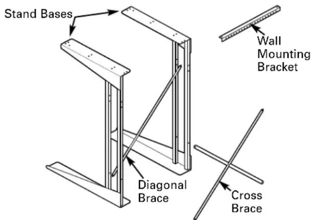
\$Stack Stand Kit
FOR USE WITH RECOMMENDED COMPACT-TYPE ELECTRIC DRYERS
Questions? Call 800.GE.CARES (800.432.2737) or visit our Web site at: www.GEAppliances.com
BEFORE YOU BEGIN
Read these instructions completely and carefully.
- IMPORTANT – Save these instructions for local electrical inspector's use.
• IMPORTANT – Observe all governing codes and ordinances. - Note to Installer – Be sure to leave these instructions with the Consumer.
- Note to Consumer – Keep these instructions for future reference.
- Installation and service must be performed by a qualified installer.
- Proper installation is the responsibility of the installer.
FOR YOUR SAFETY:
⚠ WARNING
- Electric Shock Hazard. Disconnect power before servicing. Failure to do so could result in serious injury or death.
- Potential Personal Injury. More than one person is recommended to lift the dryer into position because of its weight and size. Failure to do so could result in personal injury or death.
- Avoid Tipping and Rupture of Utility Services. Stand must be securely assembled and dryer fastened to stand, per installation instructions. Stand must be securely fastened to wall, per installaiton instructions. Failure to do so could result in personal injury/death or property damage.
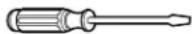
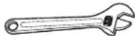
TOOLS YOU WILL NEED
- Flat-head screwdriver
- Adjustable wrench
- Nut driver

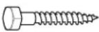
PARTS INCLUDED
| PART QUANTITY | ||
 | Lid Latch 1 | |
 | Type A Screw 2 1/4-20 × 3/4 | |
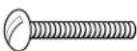 | Type B Screw 6 1/4-20 × 112 | |
 | Type C Screw 2 1/4-10 × 134 | |
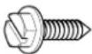 | Type D Screw 7 10-16 × 5/8 | |
 | Lock Nut 8 1/4-20 | |
| [34C6] | Spacer Ring 1 | |
PARTS INCLUDED (cont.)
text_image
Stand Bases Wall Mounting Bracket Diagonal Brace Cross BraceThe stand base has an angle bracket at each end. One end of the angle bracket is 2212 " long and has mounting holes in it. This end goes up. The other end of the angle bracket is 28" long and has no holes. This longer end (without holes) goes down.
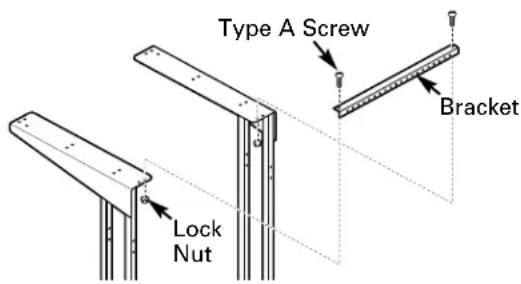
② ATTACH WALL MOUNTING BRACKET
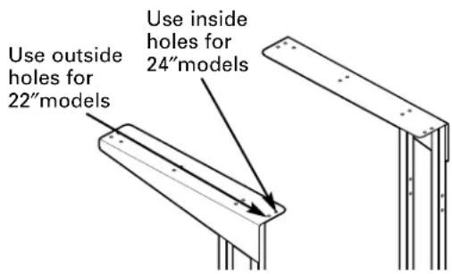
Attach one end of the wall mounting bracket to one of the upper rear holes on one of the stand bases using a Type A screw and a lock nut. Make sure screws are inserted from the top and the lock nuts are on the bottom. Use the inside hole on the stand base for 24"width. Use the outside hole for 22"width.
text_image
Type A Screw Bracket Lock NutAttach the other end of the bracket to the upper rear hole of the other stand base the same way. Use the inside hole on the stand base for 24"width or the outside hole for 22"width. Hand-tighten the screws and nuts.
① DETERMINE STAND WIDTH
Your new stand can be assembled to two different widths:
- 22"for smaller, compact washers
- 24"for larger washers
Check your washer width to determine the stand width you need. The compact dryer will assemble to either width.
text_image
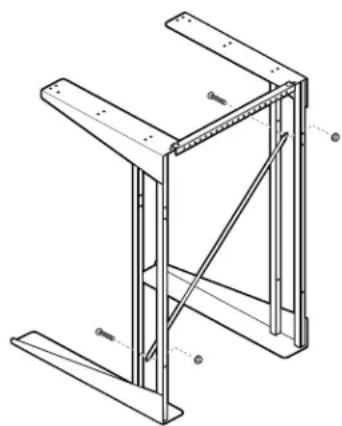
Use outside holes for 22" models Use inside holes for 24" models③ ATTACH DIAGONAL BRACE
Attach the diagonal brace to the back of the front uprights on the stand bases. The brace must run from the lower left to the upper right when viewed from the rear of the stand.
Insert a Type B screw from the front of the stand into the lower hole on the left upright and secure with a lock nut. The lock nut will be on the inside of the upright.
Insert another Type B screw into the hole on the right upright. The top hole is used for 22" width, and the lower hole is used for 24" width. Hand-tighten the screws and lock nuts.
natural_image
Technical line drawing of a structural frame with supports and diagonal braces (no text or symbols)
natural_image
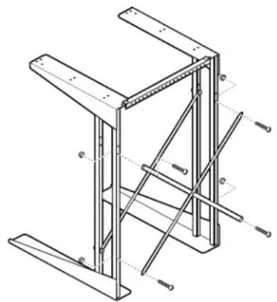
Pure technical line drawing of a mechanical bracket or support structure without any text, numbers, or symbols④ ATTACH CROSS BRACE
Attach the cross brace to the rear uprights on the stand bases.
Insert two Type B screws from the rear of the stand into the lower holes on the uprights and secure with lock nuts. The lock nuts will be on the insides of the uprights.
Insert two Type B screws into the upper holes on the uprights. The top holes are used for 22"width, and the lower holes are used for 24"width. Hand-tighten the screws and lock nuts.
natural_image
Technical line drawing of a structural frame with metal supports and bolted joints (no text or symbols)5 TIGHTEN LOCK NUTS
Securely tighten all lock nuts using a screwdriver and an adjustable wrench or nut driver.
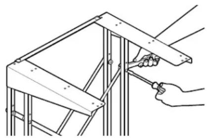
natural_image
Line drawing of a hand using a tool to adjust or install a metal frame structure (no text or symbols present)6 DETERMINE LOCATION
Locate the stand in an appropriate level area. This location should be suitable for the size, function, and protection of the stack stand and appliances. Use the stack stand only for the purpose for which it was designed. To prevent restriction of airflow, do not use top of dryer for storage.
The proper location of all utility connections is shown in the Utilities and Grounding illustration. These are not all needed in each installation, but those used should be located according to these dimensions so that utilities can be reached after installation.
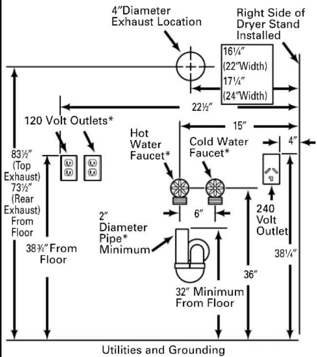
text_image
4"Diameter Exhaust Location 16½" (22"Width) 17½" (24"Width) Right Side of Dryer Stand Installed 22½" 120 Volt Outlets* 83½" (Top Exhaust) 73½" (Rear Exhaust) From Floor 38¾" From Floor Hot Water Faucet* Cold Water Faucet* 6" 240 Volt Outlet 32" Minimum From Floor 36" 4" 2" Diameter Pipe* Minimum 38¼" Utilities and Grounding6 DETERMINE LOCATION (cont.)
Dryers
Dryer models may require different utilities; refer to the Installation Instructions included with your new dryer for details on required utilities.
Refer to the Utilities and Grounding illustration and the Dryer Installation Instructions for details on final utility connections and grounding information.
NOTE: All fittings and outlets must be located so that they clear cross members of stack stand.
Automatic Washers
All automatic washers require a hot and cold water supply, a proper drain and a 120-volt electrical supply. Refer to the Installation Instructions included with your new automatic washer for detailed installation requirements.
If the automatic washer is to be operated in a different location (portable) and only stored in the stack stand, those utilities marked with an asterisk (*) in the Utilities and Grounding illustration would not be required at this location. They would be required at the location where the automatic washer is to be operated, with the exception of the drain pipe, since the machine can be drained into a sink or laundry tub.
NOTE: If both the automatic washer and dryer require a 120-volt electrical supply, TWO separate 15-ampere circuits must be used (one for each appliance). DO NOT, under any circumstances, connect both appliances to the same circuit as blown fuses will result.
⑦ LOCATE MOUNTING HOLES
Push the dryer and stand against the wall in the selected location and locate two wall studs.
Start 2 Type C screws through holes in the mounting bracket that line up with studs. DO NOT SCREW IN ALL THE WAY. Multiple holes in the bracket allow for variation in location of wall studs.
natural_image
Technical line drawing of a structural frame with metal supports and a measuring tape (no text or symbols)Once the holes are started, remove the screws from the mounting bracket and move the stand away from the wall.
For installations requiring clearance from the wall:
If the stand cannot be pushed all the way against the wall, secure a piece of wood to the wall studs to line up with the holes on the mounting bracket. The wood must be the same thickness as the clearance. Follow the steps above, starting the screws in the piece of wood.
natural_image
Technical line drawing of a mechanical assembly with no visible text or symbols8 INSTALL DRYER TO STAND
Carefully follow section entitled Preparing Your Dryer for Installation in the Installation Instructions for your new dryer. The dryer weighs approximately 100 pounds.
WARNING
Potential Personal Injury. More than one person is recommended to lift the dryer into position because of its weight and size. Failure to do so could result in personal injury or death.
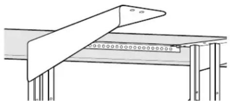
Use 6 Type D screws to secure the dryer to the stand. Tighten the screws using an adjustable wrench or nut driver. The dryer will sit approximately 1 14 forward of the end of the top angle.
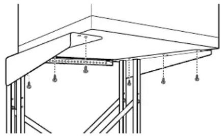
natural_image
Technical line drawing of a structural support frame with hanging weights and supports (no text or symbols)NOTE: The outside holes are used for 22" width, and the inside holes are used for 24" width.
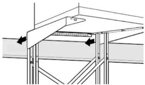
⑨ MOVE DRYER AND STAND INTO FINAL POSITION AND INSTALL DRYER EXHAUST
Push the dryer and stand against the wall in the selected location.
If the hole for the exhaust has been located as shown in the Utilities and Grounding illustration, it will align with the dryer exhaust when the stack stand and dryer are placed in the selected operating position.
natural_image
Technical diagram of a structural support frame with arrows indicating force or movement (no text or symbols present)Follow the Installation Instructions included with your dryer to make exhaust connections.
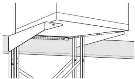
10 SECURE STAND TO WALL
After the exhaust is connected and the dryer and stack stand are in the selected operating position, secure the stand to the wall using 2 Type C screws in the holes started earlier.
natural_image
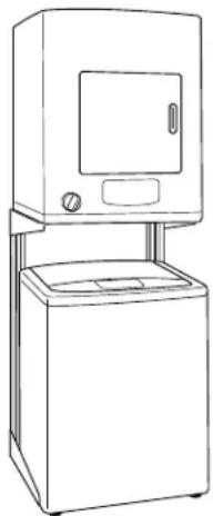
Architectural cross-section diagram of a structural framework with beams and supports (no text or symbols)11 INSTALL WASHER
Follow the Installation Instructions included with your washer to make washer connections.
After washer connections are made, move the washer into its operating position between the stand side sections and push it completely toward the rear. Use care not to kink or pinch the water inlet hose, and be sure the drain hose is placed in the drain pipe with no kinks or twists.
natural_image
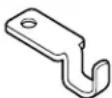
Line drawing of a simple kitchen appliance with a double door and side-mounted unit (no text or symbols)12 INSTALL LID LATCH
If a washer with a lift lid is to be installed and used under the stand, install the washer lid latch as shown using a Type D screw in the hole behind one of the front mounting holes. The lid latch may be installed on either side.
NOTE: The screw for the lid latch will thread into bottom of the dryer. Tighten securely using a nut driver.
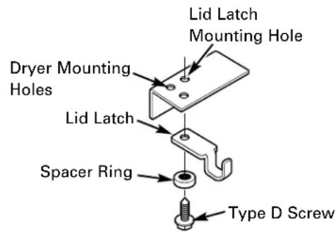
text_image
Lid Latch Mounting Hole Dryer Mounting Holes Lid Latch Spacer Ring Type D ScrewPIÈCES INCLUDES (suite)

text_image
Bases du support Applique de montage murale Entretoise diagonale Entretoise transversalenatural_image
Technical line drawing of a structural frame with diagonal bracing and support beams (no text or symbols)