
Gyspress Premium 10T Push Pull US - Riveting machine GYS - Free user manual and instructions
Find the device manual for free Gyspress Premium 10T Push Pull US GYS in PDF.
| Brand | GYS |
| Model | Gyspress Premium 10T Push Pull US |
| Product type | Pneumatic riveting machine |
| Max air pressure | 110 psi (7.6 bar) |
| Max clamping force | 100 kN (10 tons) |
| Riveter weight | 4.1 kg |
| Standard arm HR110 | Length 121 mm, opening 81 mm, depth 52 mm, weight 3 kg |
| Optional arm HR210 | Length 236 mm, opening 81 mm, depth 140 mm, weight 5.4 kg |
| Optional arm HR310 | Length 396 mm, opening 140 mm, depth 248 mm, weight 12.1 kg |
| Supported rivet types | Self-piercing rivets (Punch Rivets) and Flow-Form |
| Max sheet thickness | 8.3 mm |
| Operating modes | Manual and Automatic |
| Operating direction | Push and Pull |
| Speed adjustment | Yes, via potentiometer |
| Pressure gauge | Yes |
| Noise level | LWA = 78 dB |
| Vibrations | Less than 2.5 m/s² |
| Operating temperature | -10 to +40°C |
| Storage temperature | -20 to +55°C |
| Max humidity | 50% at 40°C, 90% at 20°C |
| Max altitude | 1000 m |
| Maintenance | Weekly cleaning, periodic visual inspection |
| Warranty (France) | 2 years parts and labor |
| Included accessories | Box of 300 steel self-piercing test rivets |
Frequently Asked Questions - Gyspress Premium 10T Push Pull US GYS
User questions about Gyspress Premium 10T Push Pull US GYS
0 question about this device. Answer the ones you know or ask your own.
Ask a new question about this device
Download the instructions for your Riveting machine in PDF format for free! Find your manual Gyspress Premium 10T Push Pull US - GYS and take your electronic device back in hand. On this page are published all the documents necessary for the use of your device. Gyspress Premium 10T Push Pull US by GYS.
USER MANUAL Gyspress Premium 10T Push Pull US GYS
natural_image
Technical line drawing of a mechanical device with no visible text or symbolsFR 02-04 / 05-14 / 25-28
EN 02-04 / 15-24 / 25-28
GYSPRESS PREMIUM 10T PUSH-PULL US
Riveteuse
Riveting machine
|
text_image
Technical diagram of a mechanical device with numbered parts for identification and assembly reference.||
text_image
HR110 169 52 81 121 215 140 81 236 HR210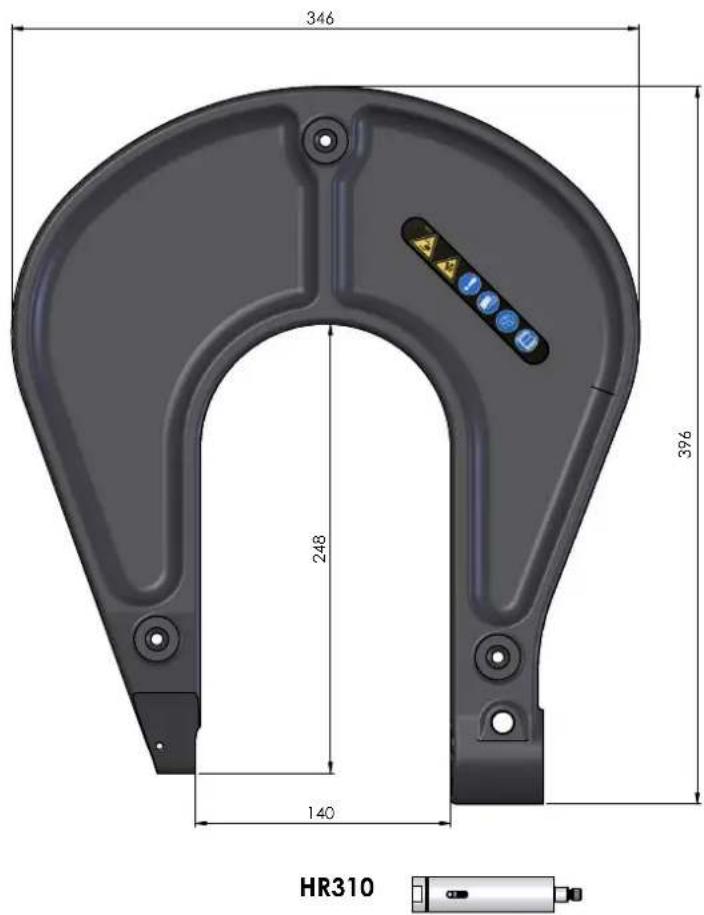
text_image
346 248 140 396 HR310COMPOSITION BOITE MATRICES / COMPOSITION BOX DIES
058361
| FR Matrices pour rivet auto-perçants (RAP)EN Matrix for self-piercing rivets (RAP)ES Matrices para remaches autoperforantes | 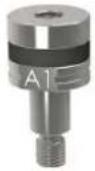 ∅ 3.2>3.5 mm ∅ 3.3 mm ∅ 3.2>3.5 mm ∅ 3.3 mm | 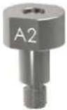 |
| FR Matrices pour rivet auto-perçants (RAP)EN Matrix for self-piercing rivets (RAP)ES Matrices para remaches autoperforantes | 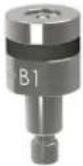 ∅ 5>5.3 mm ∅ 5.3 mm ∅ 5>5.3 mm ∅ 5.3 mm | 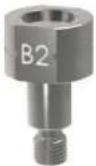 |
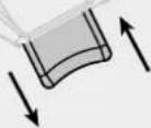
| FR Aplanissement des tôlesEN Sheet flatteningES Aplanamiento de las chapas | 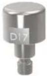 | 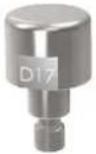 |
| FR Mandrin d'extractionEN Extraction mandrelES Mandril de extracción | 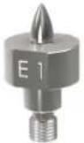 ∅ 3.3>4.8 mm ∅ 3.9>5.3 mm ∅ 3.3>4.8 mm ∅ 3.9>5.3 mm | 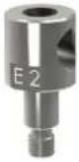 |
| FR Mandrin de poinçonnageEN Punching mandrelES Mandril de perforación | 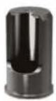 ∅ 6 mm ∅ 6 mm | 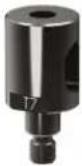 |
| FR Matrices pour rivet Flow-Form (RFF)EN Matrix for Flow-Form rivet (RFF)ES Matrices para remache Flow-Form | 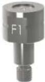 | 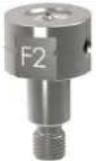 |
| FR RallongeEN ExtensionES Prolongador | 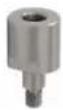 XT11-21 XT31-60 XT11-21 XT31-60 | 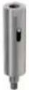 |
| FR Jeu de clés de montageEN Kit of assembly keysES Juego de llaves de montaje | 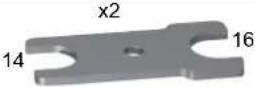 | |
| FR Bagues de rechange en élastomèreEN Spare Elastomer ringES Anillas de recambio de elastómero | 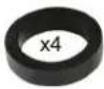 | |
| FR Pointeau centreurEN The center punchES Punzón de centrado |  | |

AVERTISSEMENTS - RÈGLES DE SÉCURITÉ
CONSIGNE GÉNÉRALE

INSTALLATION – FONCTIONNEMENT PRODUIT
DESCRIPTION
natural_image
Technical line drawing of a mechanical device showing internal components and assembly (no text or symbols)natural_image
Technical line drawing of a mechanical assembly with no visible text or symbolsnatural_image
Technical line drawings of mechanical components, showing front and side views (no text or symbols)natural_image
Technical line drawings of mechanical components, showing front and side views (no text or symbols)
natural_image
Technical line drawing of a mechanical device with an arrow indicating assembly or connection (no text or symbols present)
text_image
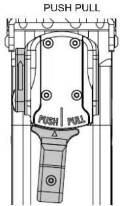
Vitesse PressionFONCTIONNEMENT DU MODE PUSH-PULL
text_image
PUSH PULL PUSH PULL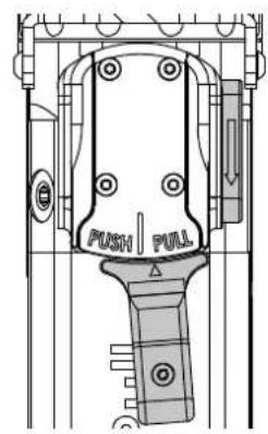
text_image
PUSH PULL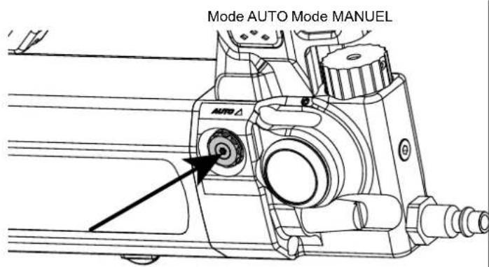
text_image
Mode AUTO Mode MANUEL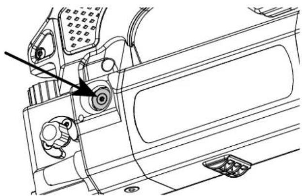
natural_image
Technical line drawing of a vehicle interior panel with no visible text or symbolsBOITE DE RIVETS FOURNIE
natural_image
Four metallic mechanical components labeled A1, A2, B1, B2, showing different mounting or fitting configurations (no text or symbols on the parts themselves)natural_image
Technical line drawing of a mechanical device with no visible text or symbols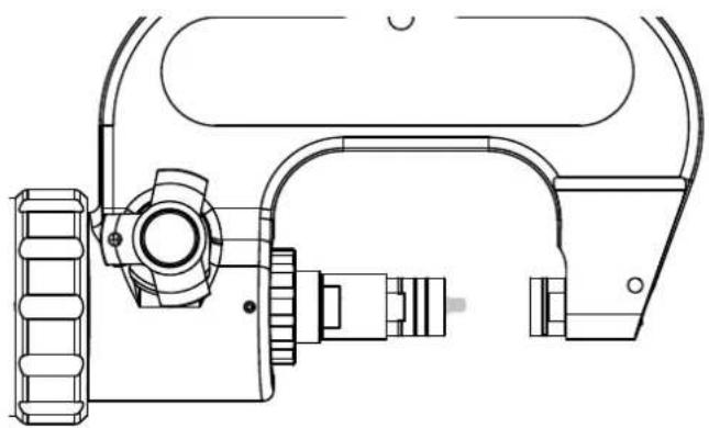
natural_image
Technical line drawing of a mechanical device with no visible text or symbolsnatural_image
Technical line drawing of a mechanical device with no visible text or symbols
natural_image
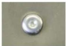
Close-up of a circular button or knob on a textured surface (no text or symbols visible)Rivet auto-perçant
POINÇONNER ET CALIBRER DES TROUS POUR RIVETS FLOW-FORM
∅ 6 mm ∅ 6 mm ∅ 6 mm
natural_image
Three metallic mechanical components with cylindrical and stepped features, shown from different angles (no text or symbols visible)ST1 T5 T7
natural_image
Close-up of a mechanical device with a metallic connector and a red arrow indicating a cutting or dissection (no text or symbols visible)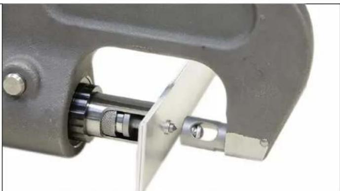
natural_image
Close-up of a mechanical clamp or bracket component with metallic parts and a central shaft (no visible text or symbols)natural_image
Close-up of a mechanical clamp or hook component with a metallic shaft and metal housing (no visible text or symbols)POSE DE RIVETS FLOW-FORM
natural_image
Close-up of a mechanical measuring instrument with a dial and adjustment knob (no visible text or symbols)natural_image
Diagram showing a cylindrical tool emitting powder into a mechanical component with a red arrow indicating direction (no text or symbols)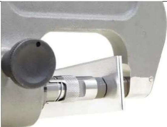
natural_image
Close-up of a metallic micrometer caliper tool (no visible text or symbols)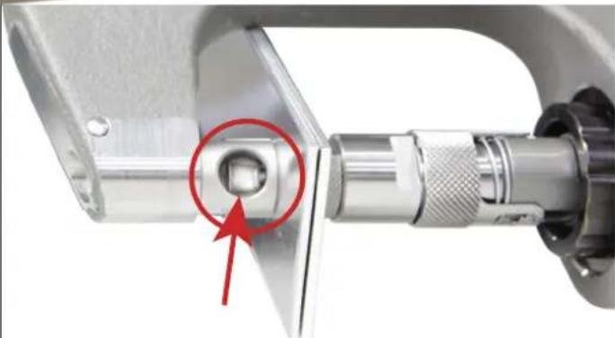
natural_image
Close-up of a mechanical clamp or connector with a red circle highlighting a bolt detail (no text or symbols visible)ANOMALIES, CAUSES, REMÈDES
OPTIONS (liste non exhaustive)
This user's manual includes operating instructions for your device and safety warnings for your protection. Please read it carefully before first use and keep it for future reference. This equipment should only be used by professionals and only qualified and experienced personnel should install, adjust, or operate it.
Do not use this tool if any parts are missing or damaged. This product must not be modified in any way.
WORKING ENVIRONMENT
Slips, trips or falls are a major cause of serious injury or death. Look out for loose cables on the floor. This appliance is not intended for use in potentially explosive atmospheres. This appliance is intended for use indoors in a well-lit environment on level ground.
ENVIRONMENT
This product must only be used within the limits indicated on the indicator plate and/or in the manual. These safety guidelines must be observed. The manufacturer cannot be held responsible in the event of improper or dangerous use.
Temperature range:
Use between -10 and +40°C (+14 and +104°F).
Store between -20 and +55°C (-4 and 131°F).
Air humidity:
Lower than or equal to 50% at 40°C (104°F).
Lower than or equal to 90% at 20°C (68°F).
Altitude:
Up to 1,000 m above sea level (3280 feet).
PROTECTING YOURSELF AND OTHERS
To protect yourself and others, please observe the following safety instructions:

Always wear impact-resistant eye protection when using the device.

Always wear a safety helmet when working at height.

Wear hearing protection in accordance with your employer's instructions, and as required by occupational health and safety regulations. Exposure to high sound levels can cause permanent hearing loss and other associated conditions, such as tinnitus. A risk assessment is crucial. Check that the mufflers are present and in good condition.

Wear protective gloves to reduce the exposure to vibration and other hazards such as cuts and abrasions. Repetitive movements and severe vibration exposure can be harmful to arms and hands, shoulders, neck and other parts of the body. If numbness, tingling, or stiffness occurs, stop using the product and consult a qualified health care professional.

Wear safety shoes in order to avoid an injury if a part is dropped during operation or assembly.
Wear warm clothing when working in cold weather to keep hands warm and dry.
Maintain a stable posture and secure footing when using the machine. It is advisable for the user to change posture during long tasks, which can help to relieve discomfort and fatigue.
The tool must not be used facing towards the operator or any other person.
Keep your hands away from the compression mechanism; it is strongly recommended to hold the riveting machine with both hands.
Be aware that broken parts of the machine can act as high-speed projectiles.
Regularly inspect for cracks; injuries may occur if the device's arm cracks and is dropped during use.
USE OF COMPRESSED AIR
Never exceed the maximum air pressure stated on the back of the machine and in this manual
Pressurised air can cause serious injury. It is recommended that the machine be disconnected from the compressed air supply before changing arms or attachments.
Empty the hose before use.
Disconnect the air supply when the tool is not in use.
Never carry the riveter by the hose
REPLACEMENT OF ARMS AND ACCESSORIES
Only use arms and accessories recommended by the manufacturer.
NOISE
Weighted sound power level: LWA = 78 dB
VIBRATION
Vibration emissions are below the imposed threshold of 2.5 m/s^2 .
STARTING THE DEVICE
If the machine is to be disposed of, it must not be left in the open and should be taken to an authorised recycling centre.
INSTALLATION - USING THE PRODUCT
DESCRIPTION
This riveting machine has been specially designed for the installation of all the main types of rivets used and approved in the automotive repair industry:
- Self-piercing rivets «Punch Rivets»
- «Flow Form» rivets
Suitable for all riveting tasks on sheet metal (up to 8.3 mm thick).
TECHNICAL FEATURES
Riveter weight 4.1 kg
Max air system pressure 110 psi
Maximum clamping force 100 kN
HANDLING
All the necessary steps for correct use are outlined in this manual. Operating procedures that are not explicitly approved by the manufacturer, GYS, are not permitted.
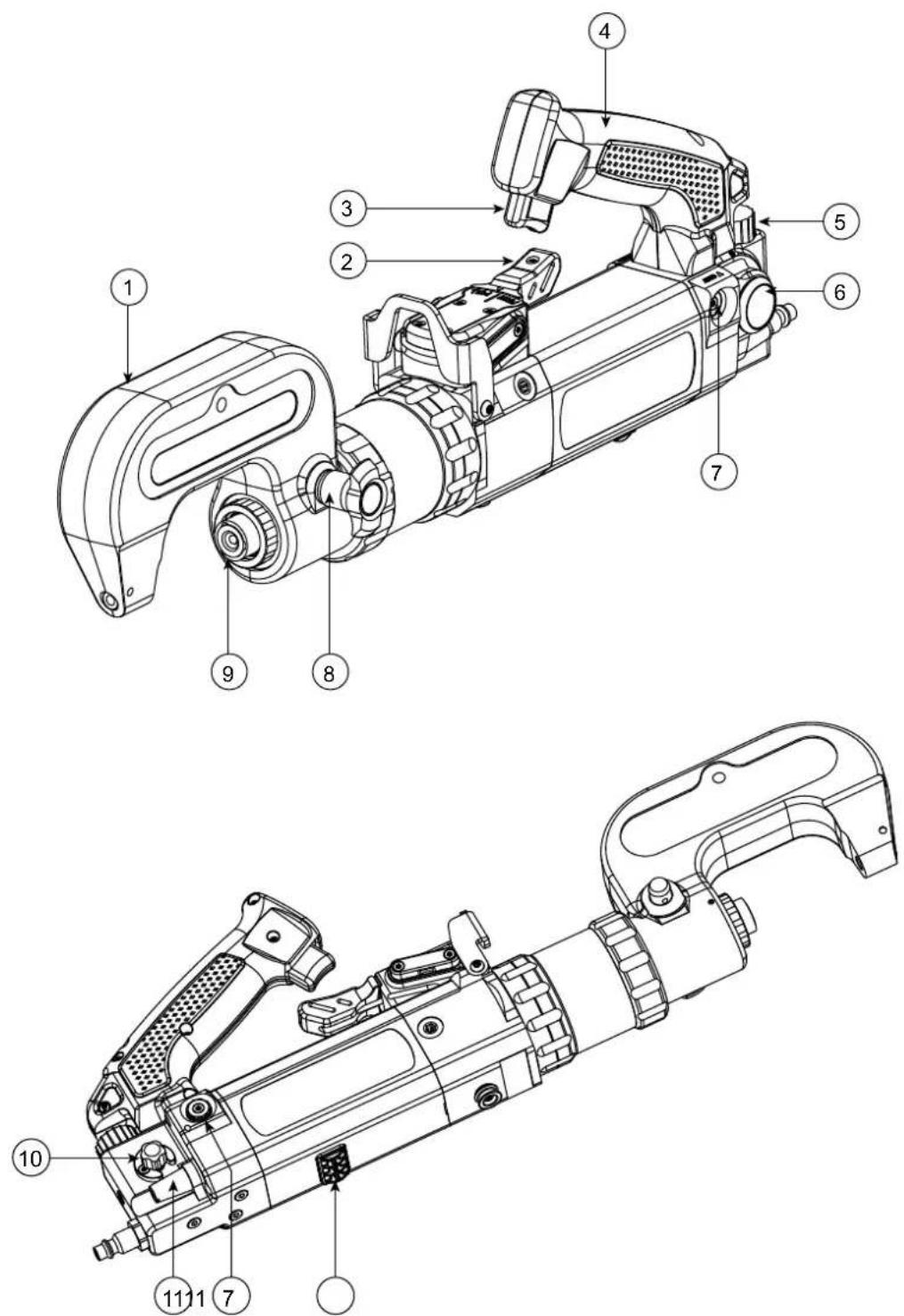
DESCRIPTION OF THE EQUIPMENT (I)
1- Steel arm 7- AUTO / MANUAL mode
2- Lever (Push / Pull) 8- Locking pin
3- Trigger 9- Cylinder shaft
4- Handle 10- Speed control
5- Air pressure adjustment 11- Air output
6- Regulator
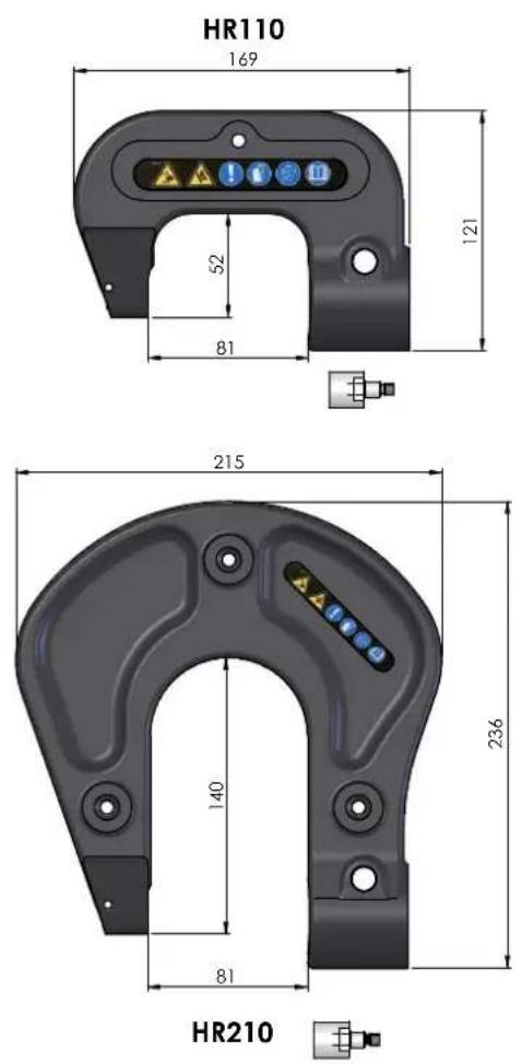
RIVETING ARM (II)
| HR110 | HR210 (optional) | HR310 (optional) | |
| Reference | 063310 | 063327 | 063334 |
| Length | 121 mm | 236 mm | 396 mm |
| Width | 50 mm | 50 mm | 50 mm |
| Height | 169 mm | 215 mm | 346 mm |
| Caliper opening | 81 mm | 81 mm | 140 mm |
| Opening depth | 52 mm | 140 mm | 248 mm |
| Weight | 3 kg | 5.4 kg | 12.1 kg |
| option | HR210 + HR310 (delivered in a case) | 064089 |
| Case only + foam for arms HR210 + HR310 | 077546 |
ARM INSTALLATION
natural_image
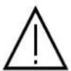
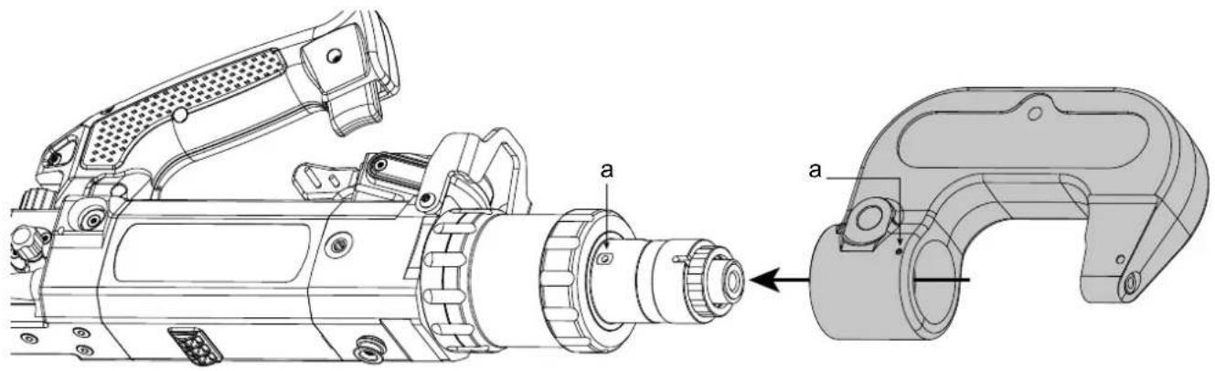
Technical line drawing of a mechanical device showing internal components and assembly (no text or symbols)Carefully place the arm on the nose of the riveter, making sure to align the 2 markings (a). When fitting large arms, it is recommended that the arms are laid flat on a table, and the nose of the riveter is brought into the arm opening.
natural_image
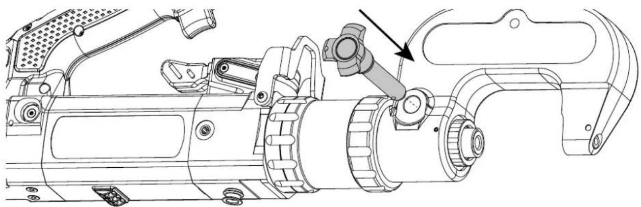
Technical line drawing of a mechanical assembly with no visible text or symbolsOnce the arm is placed on the riveter, insert the locking pin (I-8) into the slot. The pin locks automatically after insertion, and should not spontaneously escape from the slot.
The locking pin must be clean with no damage. Do not use a damaged pin.
natural_image
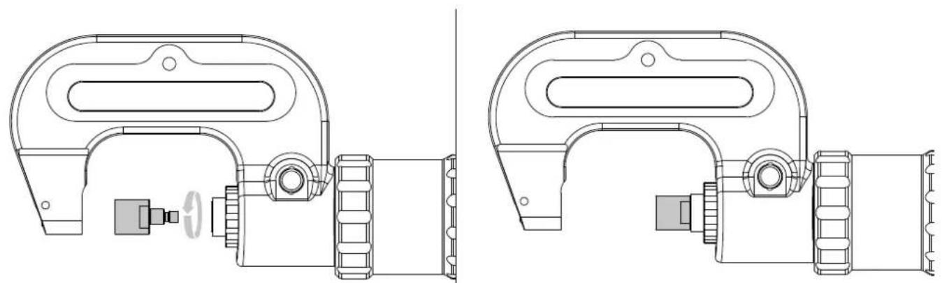
Technical line drawings of mechanical components, showing front and side views with no visible text or symbolsScrew on the extension supplied with the arm. The riveting machine is now ready to use.
MOUNTING THE FITTINGS
Screw the end-cap kit required for the riveting procedure into the arm support. Before each assembly, check that the die and rivet holder are correctly paired (see page 4) and tightened securely.
natural_image
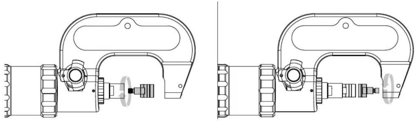
Technical line drawings of mechanical components, showing front and side views with no text or symbols
As soon as the die and the punch support are in place, finish tightening with the delivered spanner. Check that the connection tips are in place after each riveting process. Any loosening is dangerous and may cause damage to the riveter.
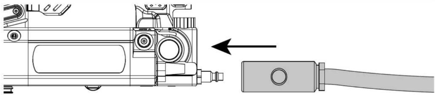
AIR PRESSURE CONNECTION
natural_image
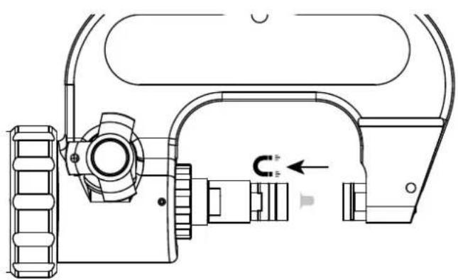
Technical line drawing of a mechanical device with an arrow indicating assembly or connection (no text or symbols present)
Maximum air pressure: Make sure that the air pressure does not exceed 110 psi.
Clean compressed air: Ensure that only clean, dry compressed air is used to feed the riveter. Moisture and dirt can lead to performance issues and/or damage to the unit.
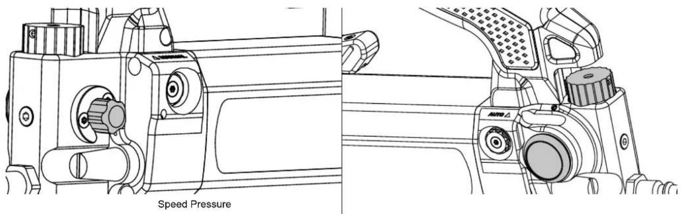
SPEED AND PRESSURE CONTROL
The user can manually adjust the speed of the ram and the rivet setting force, according to the type of material to be joined, in order to avoid any deformation of the workpiece. To set the pressure according to the dies and materials, see table at the end of the manual.
text_image
Speed Pressurenatural_image
Technical line drawing of a vehicle door panel with no visible text or symbols| AUTO / MANUAL mode Lever (Push / Pull) Trigger Cylinder action | |||
 |  |  |  |
| MANUAL | PUSH Press 0 > 100 kN |  | |
| PUSH Released STOP | |||
| PULL Released |  | ||
| PULL Press 0 > 20 kN |  | ||
| AUTO | PUSH Press 0 > 100 kN |  | |
| PUSH Released |  | ||
| PULL Released |  | ||
| PULL Press 0 > 20 kN |  | ||
RIVETS BOX INCLUDED

The riveter is supplied with a box of 300 self-piercing steel rivets (RAP) (ref. 048706). These test rivets are provided for the purpose of testing the riveter and should not be used for automotive repair under any circumstances.
INSTALLATION OF SELF-PIERCING RIVETS
∅ 3.3 mm ∅ 5.3 mm
natural_image
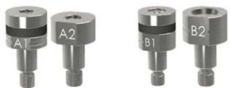
Four metallic mechanical components labeled A1, A2, B1, B2, showing different mounting or fitting configurations (no text or symbols on the parts themselves)During the installation of self-piercing rivets, make sure that the rivets are well-placed. The dies must not be damaged as this could cause problems with the riveting process.
natural_image
Technical line drawing of a mechanical device with no visible text or symbols
natural_image
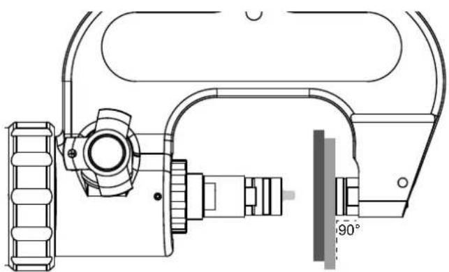
Technical line drawing of a mechanical device with no visible text or symbolsDuring each riveting procedure, it is imperative to ensure that the die - and not the rivet itself - is placed on the sheets being joined. It is also important to position the punch support on the sheets that being joined so that it forms a 90° angle.
natural_image
Technical line drawing of a mechanical assembly with no visible text or symbols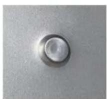
natural_image
Close-up of a circular button or knob on a textured surface (no text or symbols visible)Self-piercing rivets
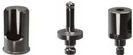
PUNCHING AND SIZING HOLES FOR FLOW-FORM RIVETS
∅ 6 mm ∅ 6 mm ∅ 6 mm
natural_image
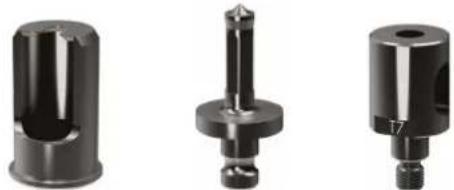
Three mechanical components shown from different angles (cylindrical, cylindrical, and stepped) with no visible text or symbols.ST1 T5 T7
To punch the sheet metal to a specific diameter, it is necessary to use a specific die. This die protects the sheet from damage.
text_image
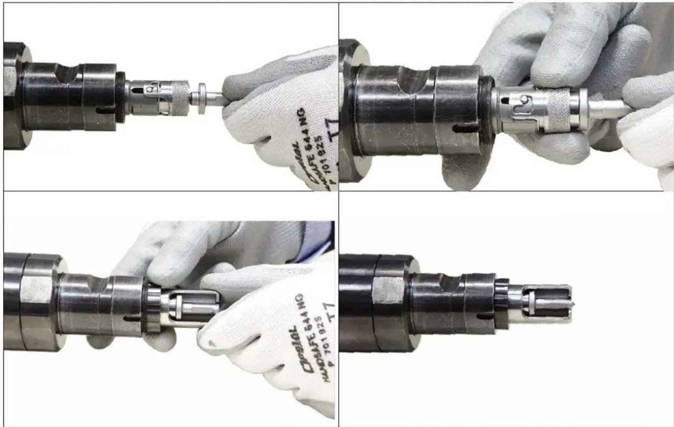
Technical procedure images showing mechanical assembly steps with labeled parts and specifications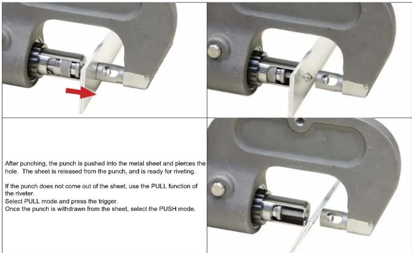
text_image
After punching, the punch is pushed into the metal sheet and pierces the hole. The sheet is released from the punch, and is ready for riveting. If the punch does not come out of the sheet, use the PULL function of the riveter. Select PULL mode and press the trigger. Once the punch is withdrawn from the sheet, select the PUSH mode.INSTALLATION OF FLOW FORM RIVETS
Before you can consider joining sheets with Flow-Form rivets, it is necessary to make a pilot hole (see above).
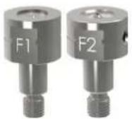
Once the pilot hole has been created, insert the Flow-Form rivet into it.
natural_image
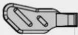
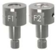
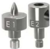
Close-up of a metallic mechanical component with a red circle highlighting a small hole, no visible text or symbols.The F1 tip should be positioned on the head side of the rivet.
natural_image
Close-up of a mechanical component being held, with red arrows pointing to a small metallic part (no visible text or symbols)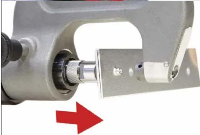
natural_image
Close-up of a mechanical clamp or bracket component with a red arrow pointing to a detail (no text or symbols visible)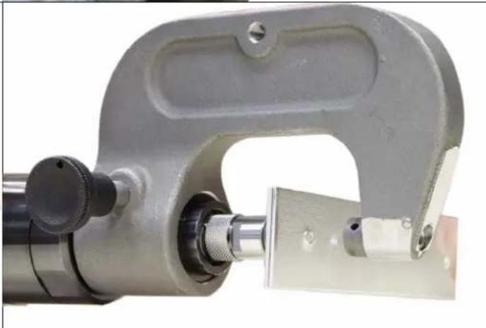
natural_image
Close-up of a mechanical tool with a metallic clamp and threaded shaft (no visible text or symbols)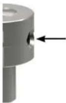
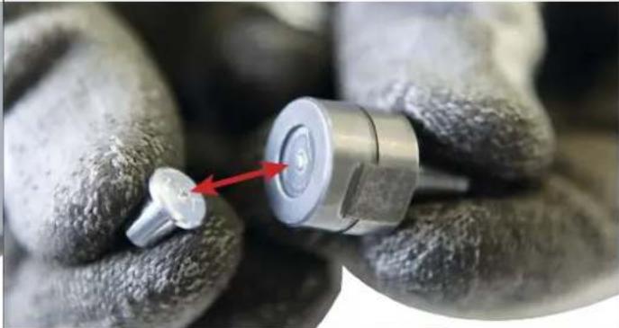
The F2 die has a drain hole for adhesive residues. After each riveting process, remove adhesive residues from all affected tools.
Flow-form rivet
RIVET EXTRACTION
For car body repairs, old or damaged rivets must be removed from the metal sheets. To avoid the necessity of removing these rivets by drilling, the extraction tip and its die should be used. They allow the rivets to be removed without damaging the sheet metal.
natural_image
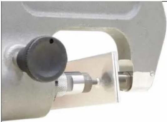
Close-up of a mechanical measuring tool with a dial and adjustment knob (no visible text or symbols)Before using the riveter, and to facilitate the extraction of self-piercing rivets, an indentation can be made on the rivet with a Centre Punch Tool (048379) so that the extraction punch can subsequently be wedged into the recess.
natural_image
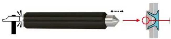
Diagram showing a cylindrical tool emitting powder into a mechanical component with a red arrow indicating direction (no text or symbols)
natural_image
Close-up of a micrometer caliper tool with adjustment knobs and a handle (no visible text or symbols)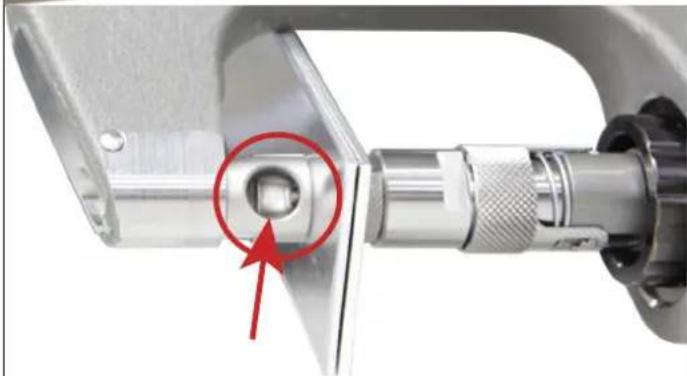
natural_image
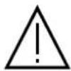
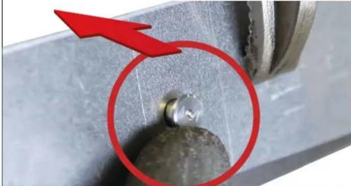
Close-up of a mechanical clamp or connector with a red arrow pointing to a circular component (no text or symbols visible)If the rivet remains in the die hole during extraction, remove it before performing another extraction.
Once the hole is punched, release the pressure immediately. Bringing the point to the end of its travel can generate additional stresses on the point, which may cause it to break.
CONTROLS AND MAINTENANCE
The riveter does not require any special maintenance. A basic periodic visual check is recommended to prevent any breakdown or failure during use.
Clean the riveter at least once a week to remove all dust and dirt that could affect the long-term performance of the product. Use self-cleaning cloths. Do not use any water, nor flammable or corrosive liquids.
During maintenance, the compressed air supply must be disconnected from the unit.
DEFECTS, CAUSES, AND SOLUTIONS
The chart below indicates the issues that can be observed during the use of the product. If the problem observed does not appear in the table below, stop using the product and call your distributor in order to find out the procedure you need to follow.
| TROUBLESHOOTING CAUSES SOLUTIONS | ||
| The riveting machine does not work. | Air supply is not attached. Connect the compressed air. | |
| Air pressure too low. Check air pressure supply. | ||
| The air pressure is not adjusted properly. Set the compressed air to between 40 and 90 psi. | ||
| The potentiometer is set to the minimum setting. Adjust the driving speed. | ||
| The rivet is not in place. | Defective chuck or die. Replace the chuck or the die. | |
| Presence of glue on the chuck or inside the die. Clean off the adhesive | ||
| The pressing pressure is not enough. Air pressure is too low or not well-ajdusted. | ||
| Rivet length wrong. Follow manufacturer instructions. | ||
| Air, leakage. | Faulty pipe. Change the pipe. | |
| Faulty coupling. Change the coupling. | ||
| Faulty seals. Repair required by the manufacturer. | ||
OPTIONS (NON-EXHAUSTIVE LIST)
| Riveter support for changing accessories | 054158 | |
| Workstation trolley | 054233 | |
| Workstation trolley + support | 055391 | |
| Pressure sensor | 062115 | |
| Adapter 24 kN for blind rivets | Standard | 063822 |
| Compact | 077164 | |
| Adapter 50 kN for blind rivets | 064867 | |
Find all riveting accessories and dies on www.gys.fr
WARRANTY CONDITIONS FRANCE
The warranty covers any defects or manufacturing faults for two years from the date of purchase (parts and labour).
The warranty does not cover:
- Any other damage caused during transport.
- The general wear and tear of parts (i.e.: cables, clamps, etc.).
- Incidents caused by misuse (incorrect power supply, dropping or dismantling).
- Environment-related faults (such as pollution, rust and dust).
In the event of a breakdown, please return the item to your distributor, along with:
- a dated proof of purchase (receipt or invoice etc.).
a note explaining the malfunction.
PRESSURE CONTROL CHART
bar
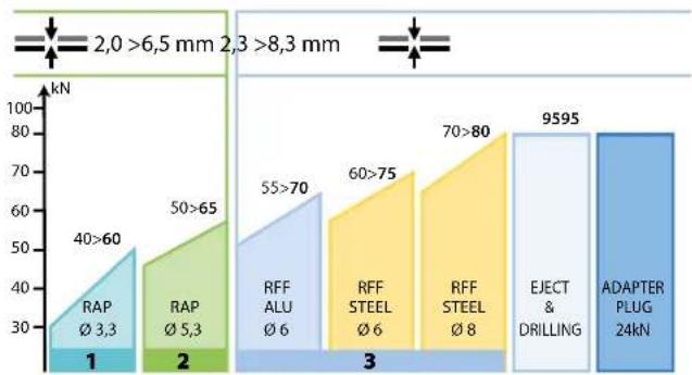
| Category | Value (kN) | |---|---| | 1 | 40>60 | | 2 | 50>65 | | 3 | 55>70 | | 4 | 60>75 | | 5 | 70>80 | | 6 | 9595 | | 7 | ADAPTER PLUG 24kN | The chart includes annotations: '2,0 >6,5 mm', '2,3 >8,3 mm', and 'EJECT & DRILLING'. The values are annotated with Ø values and corresponding ranges. The top label indicates the radius range from 2 to 6 mm.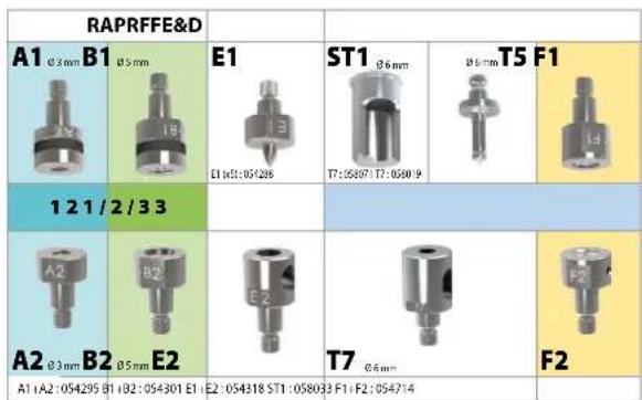
text_image
RAPRFFE&D A1 0.3 mm B1 0.5 mm E1 ST1 0.6 mm 0.5 mm T5 F1 E1 (0.3): 05/206 T7:05807 T7:05809 L3 1 2 1 / 2 / 3 3 A2 0.3 mm B2 0.5 mm E2 E2 T7 0.6 mm F2 A1 (A2):054295 B1 (B2):054301 E1 E2:054318 ST1:05803 F1+F2:054714 F2
RAP
FR Rivets Auto-Perçants
EN Self-piercing rivets (SPR)
ES Remaches autoperforantes
RFF
FR Rivets Flow-Form
EN Flow-Form rivets (FFR)
ES Remaches Flow-Form
AIR PRESSURE:
40 psi = 29 kN
50 psi = 42 kN
60 psi = 55 kN
70 psi = 68 kN
80 psi = 81 kN
90 psi = 94 kN
95 psi = 100 kN
AIR MAX:
110 psi
DIMENSIONS
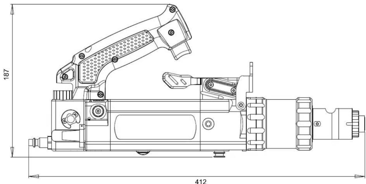
text_image
187 412SYMBOLS
 | FR Attention ! Lire le manuel d'instruction avant utilisation. EN Warning ! Read the user manual before use. ES ¡Atención! Lea el manual de instrucciones antes de su uso. |
 | FR Attention ! Risque d'écrasement des doigts. EN Warning! Risk of crushing fingers. ES Precaución. Riesgo de aplastamiento de los dedos. |
 | FR Attention ! Limite de pression d'utilisation EN Warning! Working pressure limit. ES Precaución. Limite de presión de funcionamiento |
 | FR Ce matériel faisant l'objet d'une collecte sélective selon la directive européenne 2012/19/UE. Ne pas jeter dans une poubelle domestique ! EN This hardware is subject to waste collection according to the European directives 2012/19/EU. Do not throw out in a domestic bin ! ES Este material requiere una recogida de basuras selectiva según la directiva europea 2012/19/UE. ¡No tirar este producto a la basura doméstica! |
 | FR Matériel conforme aux Directives européennes. La déclaration UE de conformité est disponible sur notre site (voir à la page de couverture). EN Device complies with europeans directives, The EU declaration of conformity is available on our website (see cover page). ES Aparato conforme a las directivas europeas. La declaración de conformidad UE está disponible en nuestra página web (dirección en la portada). |
 | FR Matériel conforme aux exigences britanniques. La déclaration de conformité britannique est disponible sur notre site (voir à la page de couverture). EN Equipment in compliance with British requirements. The British Declaration of Conformity is available on our website (see home page). ES Equipo conforme a los requisitos británicos. La Declaración de Conformidad Británica está disponible en nuestra página web (véase la portada). |
 | FR Produit recyclable qui relève d'une consigne de tri. EN This product should be recycled appropriately. ES Producto reciclable que requiere una separación determinada. |
GYS France
Siège social / Headquarter
