
WTC0823K - Air-conditioner BRANDT - Free user manual and instructions
Find the device manual for free WTC0823K BRANDT in PDF.
User questions about WTC0823K BRANDT
0 question about this device. Answer the ones you know or ask your own.
Ask a new question about this device
Download the instructions for your Air-conditioner in PDF format for free! Find your manual WTC0823K - BRANDT and take your electronic device back in hand. On this page are published all the documents necessary for the use of your device. WTC0823K by BRANDT.
USER MANUAL WTC0823K BRANDT
User Guide Trapeze Hood
Brandt
Contents
Introduction P.2
Know the various parts of your hood P.3
Safety recommendations P.3
Installation conditions P.4
Installing your hood P.5-8
Connecting your hood P.9
Using your hood P.9
Changing a bulb P.9
Cleaning your hood P.10
How to contact us ? P.11
Throughout this manual,

indicates safety recommendations,

indicates advice to help you make the best use of your duct
Introduction
Dear Customer,
Thank you for choosing the BRANDT hood.
Our design staff have produced a new generation of kitchen equipment, to make everyday cooking a pleasure.
The modern, attractive design of your new Brandt hood will blend smoothly into your kitchen installation, providing an optimum combination of easy use and performance.
The Brandt range also includes a huge choice of fitted cooking hobs, ovens, dish-washers and refrigerators, that will match your new Brandt hood.
Of course, we make every effort to ensure that our products meet all your requirements, and our Customer Relations department is at your disposal, to answer all your questions and to listen to all your suggestions (see back cover of manual).
Brandt has always been a leader in the development of new products, thus enhancing the quality of everyday life by providing increasingly efficient products, that are easy to use, respect the environment, and are attractive and reliable.
The BRANDT name.
Know the various parts of your Hood ?
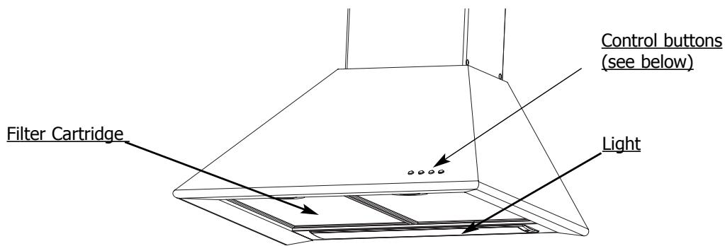
3-speed model
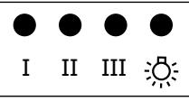
I Slow speed II Medium speed III Fast speed Lighting
Note: If more than one speed button has been depressed, the hood operates at the fastest.
The hood stops working when no buttons are depressed.

Safety recommendations
Please become familiar with the safety recommendations, before installing and using your hood.
This hood is designed for normal household use. This hood contains no asbestos.
-
Do not allow naked flames to burn beneath the duct, i.e. do not cook " flambe " dishes or allow a gas ring to burn with no receptacle placed on it (extracted flames could damage the duct).
-
Frying under the duct should be constantly monitored.
- Repair work should only be carried out by an approved specialist.
- The metal filters should be regularly cleaned.
- The hood must not be installed or used over a fuel burning (wood, coal, etc.) stove.
To obtain optimum efficiency from your hood:
- You should preferably use the rear cooking rings on your cooker. We recommend that the hood should be switched on from the beginning of the cooking and, in certain cases, may be allowed to run for a few minutes after the end of the cooking.
Note :
- When a cooking hood is used simultaneously with other equipment burning gas or similar fuels, the room must be adequately ventilated.
When the duct is running at max. power, the air in a kitchen is entirely evacuated, and thus replaced, in a few minutes.
IMPORTANT
-
In the case of a kitchen heated by equipment connected to a chimney (e.g. a stove, etc.), the hood must be installed in recirculating mode.
-
Do not use the hood without the metal filters.
Installation conditions
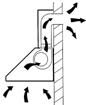
If you have an air outlet to outdoors:
Your hood can be connected to this outlet through an evacuation duct (enamel finished, in aluminium, flex-hose or other non-inflammable material), with internal diameter 150mm (not supplied).
Otherwise, an adapter may be used to connect your hood to an evacuation duct with internal diameter 125 mm (supplied with your hood).
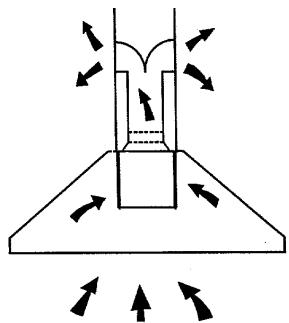
If you have no air outlet to outdoors:
All our units can be used in recirculating mode (with no outlet to outdoors).
In this case, an active carbon filter should be installed, to eliminate smells.
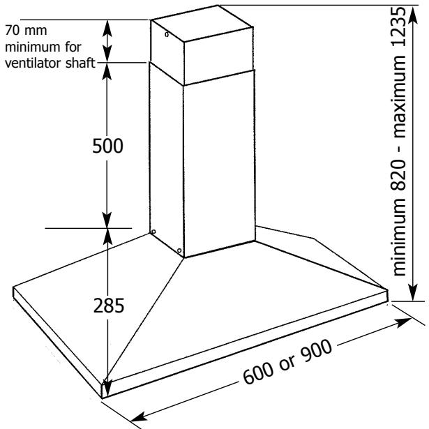
Width:
600 or 900 mm Depending on model
Depth:
500 mm
Overall height under
conduit:
285 mm
Overall height:
820/1235
Outlet outer diameter:
150 mm (with non-return valve) or 125 mm.
Installing your hood
1. Pre-installation recommendations:
The distance between the cooking plane and the bottom of the hood must not be less than 70~cm . If the instructions of the gas cooker installed under the hood specify a distance greater than 70~cm , then this distance must be respected.
Proceed as follows:
- Mark a vertical line on the wall, to ensure that your hood (and its chimney) are perfectly aligned with your cooker.
- Make a mark, on the vertical line, at least 70~cm above your cooking plane. The vertical line and the mark at 70~cm will help you set up the installation as shown in the attached installation diagram.
2. Installing the body of the hood:
-
Place the installation diagram supplied against the wall, and align the vertical line on the wall with the "hood centreline" shown on the diagram.
-
Drill four holes, dia. 8mm , as shown on the diagram.
-
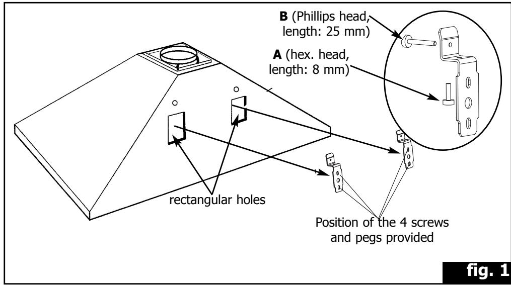
Mount the two supports on the wall, using the four screws and plugs supplied with the duct (fig. 1).
Remark: In the case of a hollow wall, use the appropriate screws and plugs.
- Mount the hood by locating its rectangular holes on the supports.
The width of the holes is sufficient to allow some margin for left/right adjustment.
IMPORTANT :
- Adjust the height and levelling using the support adjustment screws " A " (fig.1), and then mount the hood firmly against the wall by tightening the screws " B " (fig. 1).
Installing your hood

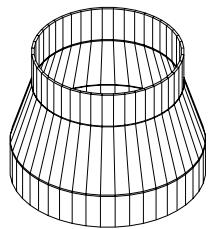
fig. 4
chimney mounting
fig. 3
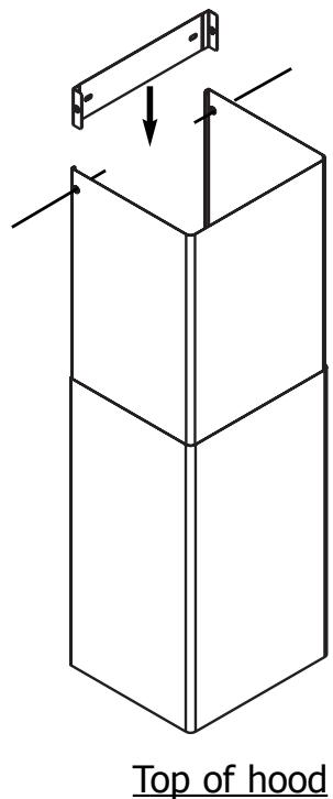
fig. 5
Installing your hood
3. Assembling the ventilation shaft for ducting outdoors:
a) Operation with evacuation to outdoors
The installation must comply with applicable regulations concerning room ventilation. In particular, evacuated air must not be transferred through a conduit used to evacuate fumes from equipment burning gas or similar fuels.
Unused and existing conduits can only be used following approval by a qualified specialist.
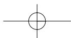
- Remove the two mounting screws from the plastic deflector (fig.6).
The plastic deflector is only used for an installation in recirculating mode.
- Push the non-return valves (fig.2) into the hood outlet pipe. Remove the adhesive tape retaining the valves.
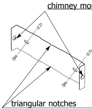
- Recover the chimney support plate (fig.3).
- Mount the metal chimney support on the wall, in contact with the ceiling (fig.3).
Check that the two triangular notches are aligned with the vertical line on the wall (drill dia. 8 mm, two screws and plugs supplied). - Engage and secure the evacuation duct, dia. 150mm (not supplied) in the hood outlet pipe.
- In the case of a duct, dia. 125 mm, use the adapter supplied (fig.4).
- Prepare your telescopic chimney, carefully covering the vents (fig.5).
Push the chimney sections, one into the other, as far as possible. - Mount the upper part of the inner chimney on the metal support, using the screws supplied (to facilitate installation, pull the chimney slightly clear, so that the two returns can be inserted behind the metal support).
- Adjust the length of the chimney by sliding the outer part down and sitting it in the top of the hood.
Installation recommendations:
For optimum use of your hood, we recommend that it be connected to a duct of diameter 150~mm . Keep the number of angles and the duct length to a minimum.
If your extractor hood is being used to dispel air outside, make sure your kitchen has a fresh-air vent so that it does not become deprived of oxygen.
Installation of your hood
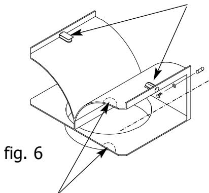
chimney mounting
Check whether notches are required to get the power cable through

fig. 7
Top of hood
4. Assembling the ventilation shaft for recirculating the air
In this case, non-return valves are not required.
- Remove the two mounting screws from the plastic deflector (fig. 6).
- Mount the plastic fumes deflector against the wall, in contact with the ceiling (drill two holes, dia. 8 mm, 200 mm apart, and use the screws and plugs supplied) (fig. 6).
Check that the deflector is central, in relation to the vertical line on the wall.
- Mount the evacuation duct (dia. 150 mm, not supplied) between the deflector and the hood.
- Prepare your chimney, ensuring that the vents are towards the top and visible (fig. 7). Push the chimney sections one into the other, as far as possible.
- Mount the upper part of the chimney on the plastic deflector, using the screws supplied (to facilitate installation, pull the chimney slightly clear, so that the two returns can be inserted behind the plastic deflector).
- Adjust the length of the chimney by sliding the outer part down and sitting it in the top of the hood.s
Connecting your hood
Your hood is supplied with a power cable H05VVF, with three wires, section 0.75mm^2 (neutral + phase and earth). Your hood should be connected to a 230 V single phase mains power supply, through a standard power socket CEI 83, which should remain accessible following the installation of the finishing panels, or through an omni-polar cutout, with a contact opening gap of at least 3 mm. If the power cable is damaged, contact an authorised Brandt service agent.
Your installation should include a fuse, rating 10 A or 16 A.
Using your hood
Low speed:
- for simmering and dishes that create little steam,
- to create ventilation in the kitchen.
Medium speed:
- for normal cooking.
Maximum speed:
- for cooking creating considerable fumes or steam (frying, pressure cooker).
Reset medium power immediately maximum power is no longer required.
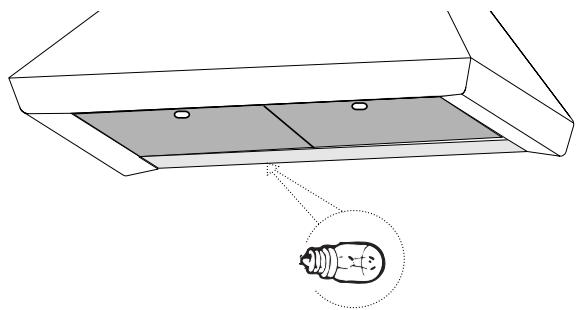
Changing a bulb
Before carrying out any work, switch off the hood either by unplugging the power connector or by tripping the circuit breaker.
BULB-LIT VERSION
- Undo the screw of the shade.
- Swing it away.
-
- For models with an E14 40-watt bulb, unscrew the bulb and insert a new one.
- Replace the shade.
- Replace the screw.
Cleaning your hood
The hood should be switched off before the metal filters are removed. After cleaning, the metal filters should be installed, as described in the instructions.
1. ROUTINE MAINTENANCE
Never use metal cleaning pads, abrasive products or excessively hard brushes. Do not clean the stainless steel using ammonia-based products.
To clean the outer casing and the lighting window, use only household cleaning products, diluted in water, rinse with clean water and wipe with a soft cloth.
2. MONTHLY MAINTENANCE: metal filter
The filter retains greasy vapours and dust, and is very important for the efficient operation of your hood.
It can progressively become inflammable, as it becomes saturated with greasy residue. Clean the metal filter using commercial household cleaner, rinse thoroughly and dry. In the dishwasher, this cleaning should be done using the filter only, in the vertical position. Do not clean the filter at the same time as the dirty dishes because of the risk of leaving stains. Before using the metal filter for the first time, remove the protective film.
-
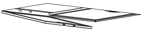
To remove the metal filter:
-
Raise the filter handle.
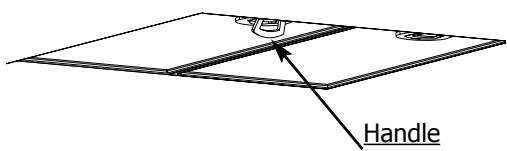
- Rotate the filter downwards.
After cleaning, install the filter by carrying out the above operations, in the reverse sequence.
3. ANNUAL MAINTENANCE: active carbon filter
ONLY for hoods operating in recirculating mode (not connected to an evacuation to outdoors). This filter retains smells and should be changed at least annually, as a function of utilisation and to avoid any risk of fire. Filters may be obtained from your Brandt dealer (see part number shown on identification plate, inside the hood). Note the installation date of a new filter.
Before carrying out any work on the hood, check that it is switched off.
How to contact us
In the spaces below, copy the reference numbers from your hood identification plate:
Brandt
MADE IN FRANCE
230V 50 Hz
BRANDT APPLIANCES SAS 7 rue Henri Bequerel 92500 RUEIL MALMAISON

N^ SER. TYPE REF CARBON FILTER : CONS.N°419

9962 8071 01/03