
HDZIT301 - Kitchen accessory BOSCH - Free user manual and instructions
Find the device manual for free HDZIT301 BOSCH in PDF.

| Product Type | Kitchen accessory - Island trim |
| Brand | Bosch |
| Model | HDZIT301 |
| Compatibility | Bosch built-in ranges HGI8054, HGIP054, HDI8054, HDIP054 |
| Material | Stainless steel |
| Approximate dimensions | Width: 762 mm (30 in), Depth: 50 mm (2 in), Height: 50 mm (2 in) |
| Approximate weight | 1.5 kg |
| Kit contents | Island trim, spacer screws (5), fastening screws (2) |
| Main functions | Aesthetic cover for built-in island range, edge protection |
| Installation | Remove original trim, install island trim using provided screws |
| Required tools | Torx T20 screwdriver, gloves |
| Care and cleaning | Clean with a soft cloth and non-abrasive cleaner |
| Safety | Follow safety instructions, do not block vents, check anti-tip bracket |
| Spare parts and repairability | Contact a qualified installer or Bosch customer service |
| General information | User manual available for download on the manufacturer's website |
Frequently Asked Questions - HDZIT301 BOSCH
User questions about HDZIT301 BOSCH
0 question about this device. Answer the ones you know or ask your own.
Ask a new question about this device
Download the instructions for your Kitchen accessory in PDF format for free! Find your manual HDZIT301 - BOSCH and take your electronic device back in hand. On this page are published all the documents necessary for the use of your device. HDZIT301 by BOSCH.
USER MANUAL HDZIT301 BOSCH
For Island Trim Kits
MANUEL D'INSTALLATION
This indicates that death or serious injuries may occur as a result of non-observance of this warning.

CAUTION
This indicates that minor or moderate injuries may occur as a result of non-observance of this warning.
NOTICE: This indicates that damage to the appliance or property may occur as a result of non-compliance with this advisory.
Note: This alerts you to important information and/or tips.

WARNING:
If the information in this manual is not followed exactly, a fire or explosion may result causing property damage, personal injury or death.
-- Do not store or use combustible materials, gasoline or other flammable vapors and liquids in the vicinity of this or any other appliance.
-- WHAT TO DO IF YOU SMELL GAS
- Do not try to light any appliance.
- Do not touch any electrical switch.
- Do not use any phone in your building.
- Immediately call your gas supplier from a neighbor's phone. Follow the gas supplier's instructions.
- If you cannot reach your gas supplier, call the fire department.
-- Installation and service must be performed by a qualified installer, authorized service agency or the gas supplier.

IMPORTANT SAFETY INSTRUCTIONS
READ AND SAVE THESE INSTRUCTIONS

WARNING
- If the information in this manual is not followed exactly, property damage or personal injury may result.
- Read the instructions completely before attempting one of these procedures.
• Installation of Island Trim requires access to the mounting screws on the back and sides of the range. If electrical or gas connections prevent access to the screws, contact a qualified technician before proceeding.

WARNING
- DO NOT block or obstruct the flow of air through the ventilation openings. The oven vents are located at the back of the range. The vents need to be unobstructed and open to provide necessary airflow for proper oven performance.
- DO NOT touch the oven vent area while the range is on and for several minutes after the range is off. Some parts of the vents and surrounding area become hot enough to cause burns. Allow range sufficient time to cool before touching or cleaning vent areas.
- DO NOT position plastic or other heat sensitive items on or near the oven vents. These items could melt or ignite.
Appliance Handling Safety

CAUTION
- The range is heavy and requires at least two persons or proper equipment to move.
- Hidden surfaces may have sharp edges. Use gloves and caution when reaching behind or under appliance.
Do not move the range using the oven door handle. You may wish to remove the oven door for easier handling. See the Installation Manual for your range for more information.
Turn power OFF at the service panel. Lock service panel to prevent power from being turned ON accidentally.
Refer to range data plate for more information. See the Installation Manual for your range for the data plate location.

WARNING
TIP OVER HAZARD!
A child or adult can tip the range over and be killed. Verify that the anti-tip bracket is securely installed. Ensure the anti-tip bracket is engaged whenever the range is moved to a new location.

natural_image
Silhouette of a person pushing a large block on a flat surface (no text or symbols)Do not operate the range without the anti-tip bracket in place. Failure to follow the instructions in this manual can result in death or serious burns to children and adults.
Check for proper installation and use of the anti-tip bracket. Carefully tip the range forward pulling from the back to ensure that the anti-tip bracket engages the range leg and prevents tip-over. Range should not move more than 1" (25 mm).
NOTICE
Proper Handling Technique
To avoid risk of damage to the range oven door, do not lift, push, or pull the range by holding the door handle. Take care not to touch the oven heating element (dual fuel range) also located at the top of the oven cavity, just behind the ridged area.

Note: It is recommended to wear gloves and long sleeves to protect hands and forearms from abrasion and potential scratches during the sliding process. It is also recommended to take off watches and jewelry and to wear work shoes during installation for foot protection.
Island Trim Installation
Island Trim Installation Recommendations
The Island Trim is intended for slide-in range installations in a kitchen island or peninsula, not for installations against a wall.
To help prevent inadvertent contact with a hot Island Trim, it is suggested that a minimum 6" (152.4 mm) clearance be maintained between the rear and sides of the slide-in range cut out and the outside of the island. Figure 1: Minimum recommended range cut out clearance. See the Slide-In Range Installation Manual for other clearance information.
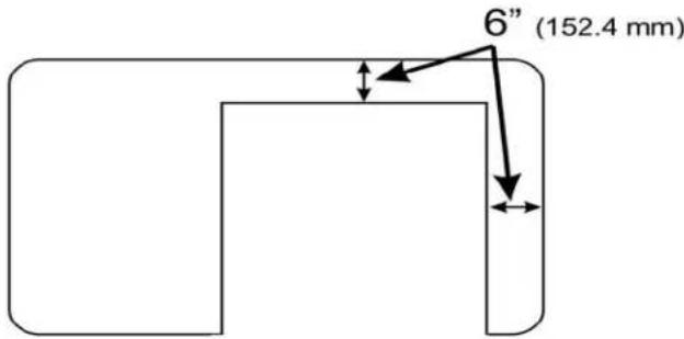
Figure 1: Minimum recommended range cut out clearance
Procedure for a Gas Slide-In Range (HGI8054, HGIP054 ranges only)
Tools Needed
- Torx T20 screwdriver
• g l o v e s
Preparation
IMPORTANT!
Can the range slide out enough to give access to the rear and side screws of the rear louver cover and rear vent trim? See Figure 2: Rear louver cover screw locations and Figure 3: Trim screw locations (louver cover removed).
- If the range can slide out, continue to the Procedure.
- If the range cannot slide out, contact a qualified service person to disconnect the gas or electrical connections that prevent the range from being pulled out before continuing to the Procedure.
- Read the Tip Over Warning in the Safety section of this manual. Be aware of this when the range has been pulled out of the anti-tip bracket for this installation.
Procedure
- Confirm that the range surfaces and cooktop grates are cool enough to be comfortably touched.
- Slide the range out enough to access the rear louver cover mounting screws. Read the Proper Handling Technique Notice in the Safety Section of this manual.
- Remove the four screws holding the rear louver cover. Save these screws to reattach the louver cover. See Figure 2: Rear louver cover screw locations.
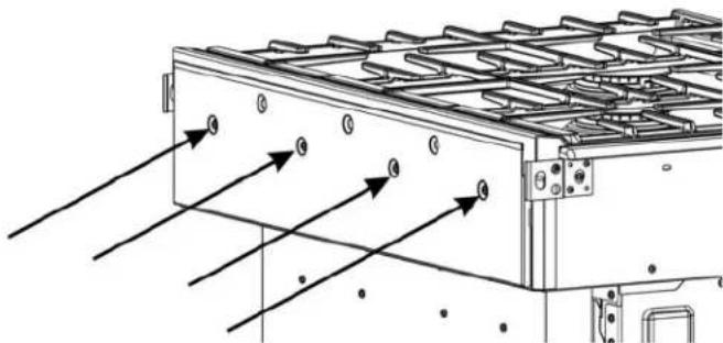
natural_image
Technical line drawing of a heat exchanger or cooling unit with directional arrows indicating flow (no text or symbols present)Figure 2: Rear louver cover screw locations
- Lift the louver cover out of the slots holding it in place. Note the slot locations for later. See Figure 3: Trim screw locations (louver cover removed).
- Remove the cooktop grates.
- Remove the screws holding the trim (five screws on the back and one screw on each end). Save two of these screws for installation of Island Trim. See Figure 3: Trim screw locations (louver cover removed).
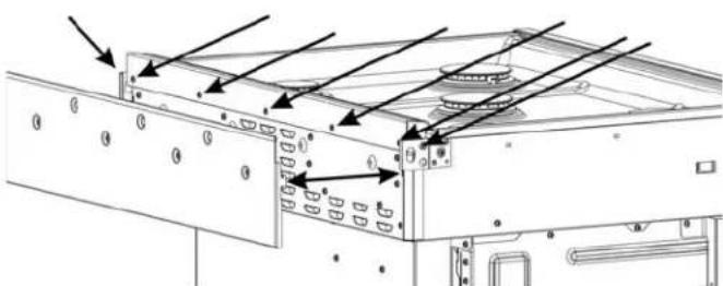
Figure 3: Trim screw locations (louver cover removed)
-
Rotate the trim forward and lift it off.
-
Install five stand-off screws (included in the Island Trim kit) in the back of the range, in the same locations as the original 5 rear trim screws. See .Figure 3: Trim screw locations (louver cover removed)

natural_image
Technical line drawing of a screw with threaded head and flange (no text or symbols)Figure 4: Stand-off Screws
- Place the rear louver cover into its slots and secure with the four original screws.
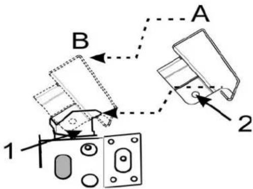
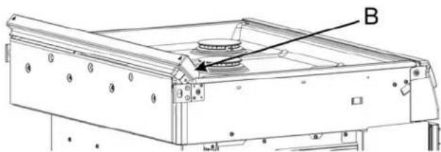
- Place the Island Trim in position A (Figure 5: Island Trim placement 1) and move it to position B (towards the rear of the range) as shown to engage the alignment device 1 (the appearance of the device may not be exactly as shown).
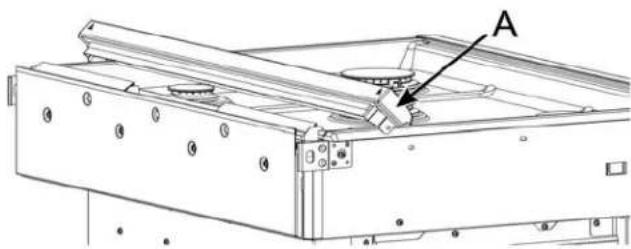
natural_image
Technical line drawing of a mechanical device with labeled component B (no text or symbols beyond label)Figure 5: Island Trim placement 1
- Rotate the Island Trim into position where the Island Trim side mounting hole 2 is visible through hole 3 on both sides of the range(see Figure 6: Island Trim placement 2.
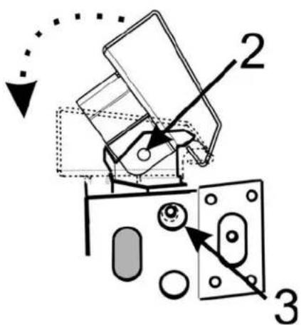
Figure 6: Island Trim placement 2
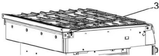
- Secure the Island Trim with one screw through hole 3 at each end (see "Island Trim placement 2" on page 4 and "Island Trim Installed" on page 4).
- Replace the cooktop grates back into their normal positions.
natural_image
Technical line drawing of a rectangular industrial or mechanical component with grid-like top structure and mounting base (no text or symbols)Figure 7: Island Trim Installed
- If necessary, have a qualified service person reattach electrical or gas connections.
- Slide the range back into position, being sure to engage the anti-tip bracket. See the Tip Over Hazard Warning earlier in this instruction and also in the Slide-In Range Installation Manual.
Procedure for a Dual Fuel Slide-In Range (HDI8054, HDIP054 ranges only)
Tools Needed
- Torx T20 screwdriver
• g l o v e s
Preparation IMPORTANT!
Can the range slide out enough to have access to the rear and side trim screws? See Figure 1: Trim Screws, Dual Fuel Range.
- If the range can slide out, go to the Procedure.
- If the range cannot out, contact a qualified service person to disconnect the gas or electrical connections that prevent the range from being pulled out before continuing to the Procedure.
- Read the Tip Over Warning in the Safety section of this manual. Be aware of this hazard when the range has been pulled out for this installation.
Procedure
- Confirm that the range surfaces and cooktop grates are cool enough to be comfortably touched.
- Slide the range out enough to access the trim mounting screws (see Figure 1: Trim Screws, Dual Fuel Range).
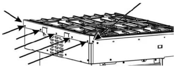
natural_image
Technical diagram of a roof structure with directional arrows indicating airflow or force (no text or symbols)Figure 1: Trim Screws, Dual Fuel Range
- Remove the cooktop grates.
- Remove the screws holding the trim (five screws on the back and one screw on each end). Save the screws for installing the Island Trim (see Figure 1: Trim Screws, Dual Fuel Range).
- Lift the trim up to remove.
- Lower the Island Trim into place, aligning the Island Trim hole 1 with the hole at 2 on both sides of the range. See Figure 2: Island Trim placement.
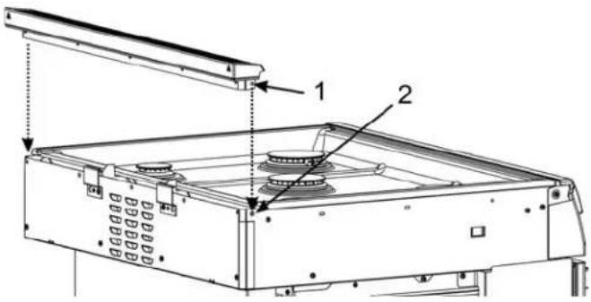
Figure 2: Island Trim placement
- Secure the Island Trim with one screw at each end and five screws in the back. See Figure 1: Trim Screws, Dual Fuel Range.
- Replace the cooktop grates back into their normal positions,
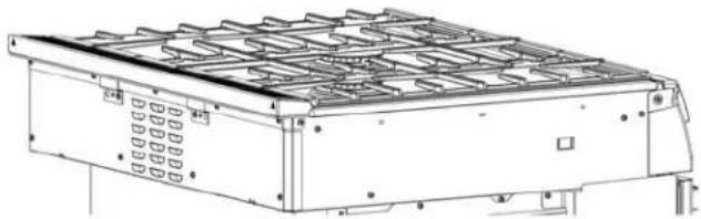
natural_image
Technical line drawing of a mechanical enclosure or housing unit with grid-like internal components (no text or symbols)Figure 3: New Island Trim Installed
- If necessary, have a qualified service person reattach electrical or gas connections.
- Slide the range back into position, being sure to engage the anti-tip bracket. See the Tip Over Hazard Warning earlier in this instruction and also in the Slide-In Range Installation Manual.
natural_image
Silhouette of a person pushing a large object upward (no text or symbols)Bonne technique de manutention
natural_image
Technical line drawing of a heat exchanger or cooling unit with directional arrows indicating airflow or heat transfer (no text or symbols present)natural_image
Technical line drawing of a screw with threaded head and flange (no text or symbols)natural_image
Technical line drawing of a rectangular industrial or mechanical component with grid-like top structure and mounting points (no text or symbols)natural_image
Technical diagram of a heat exchanger or cooling unit with airflow arrows and structural components (no text or labels)natural_image
Technical line drawing of a mechanical enclosure or enclosure with grid-like panels and ventilation grilles (no text or symbols)natural_image
Silhouette of a person pushing a large block with a stick (no text or symbols)natural_image
Technical line drawing of a heat exchanger or cooling unit with directional arrows indicating airflow or heat transfer (no text or symbols present)natural_image
Technical line drawing of a screw with threaded head and flange (no text or symbols)Figura 4: Tornillos separadores
natural_image
Technical line drawing of a rectangular industrial or mechanical component with grid-like top structure and mounting points (no text or symbols)Figura 7: Moldura para islas instalada
natural_image
Technical diagram of a heat exchanger or cooling unit with airflow arrows and structural components (no text or labels)Figure 1: Tornillos de la moldura, estufa de dos combustibles
natural_image
Technical line drawing of a mechanical housing or enclosure with grid-like panels and ventilation slots (no text or symbols)
- MANUEL D'INSTALLATION
- CAUTION
- WARNING:
- IMPORTANT SAFETY INSTRUCTIONS
- READ AND SAVE THESE INSTRUCTIONS
- WARNING
- Appliance Handling Safety
- TIP OVER HAZARD!
- NOTICE
- Proper Handling Technique
- Island Trim Installation
- Island Trim Installation Recommendations
- Procedure for a Gas Slide-In Range (HGI8054, HGIP054 ranges only)
- Tools Needed
- Preparation
- Procedure
- Procedure for a Dual Fuel Slide-In Range (HDI8054, HDIP054 ranges only)
- Preparation IMPORTANT!
- Bonne technique de manutention
Brand : BOSCH
Model : HDZIT301
Category : Kitchen accessory