
HEZBS301 - Hob BOSCH - Free user manual and instructions
Find the device manual for free HEZBS301 BOSCH in PDF.

| Product type | Low backsplash (rear trim) for cooktop |
| Brand | Bosch |
| Model | HEZBS301 |
| Compatibility | Built-in gas (HGZBS301) and electric/induction (HEBZS301) cooktops |
| Material | Metal (stainless steel or similar) |
| Color | Stainless steel (typical) |
| Dimensions | Designed to fit the back of the cooktop (standard backsplash height) |
| Weight | Approximately 2-3 kg (estimated) |
| Power supply | None (mechanical accessory) |
| Main function | Protect the wall from splashes and improve the cooktop's appearance |
| Installation | Fastening using Torx T20 screws, requires sliding the cooktop forward |
| Required tools | Torx T20 screwdriver, protective gloves |
| Package contents | Low backsplash, mounting screws (5 rear + 2 side), ventilation grille (already present on cooktop) |
| Maintenance and cleaning | Clean with a soft damp cloth, avoid abrasives |
| Safety | Important: check the cooktop's anti-tip bracket before and after installation |
| Repairability | Official Bosch replacement part, replacement possible by a professional |
| Warranty | Standard manufacturer warranty (see Bosch terms) |
| General information | User and installation manual provided, free to download |
Frequently Asked Questions - HEZBS301 BOSCH
User questions about HEZBS301 BOSCH
0 question about this device. Answer the ones you know or ask your own.
Ask a new question about this device
Download the instructions for your Hob in PDF format for free! Find your manual HEZBS301 - BOSCH and take your electronic device back in hand. On this page are published all the documents necessary for the use of your device. HEZBS301 by BOSCH.
USER MANUAL HEZBS301 BOSCH
For Low Backguard Trim
MANUEL D'INSTALLATION
This indicates that death or serious injuries may occur as a result of non-observance of this warning.

CAUTION
This indicates that minor or moderate injuries may occur as a result of non-observance of this warning.
NOTICE: This indicates that damage to the appliance or property may occur as a result of non-compliance with this advisory.
Note: This alerts you to important information and/or tips.

WARNING:
If the information in this manual is not followed exactly, a fire or explosion may result causing property damage, personal injury or death.
-- Do not store or use combustible materials, gasoline or other flammable vapors and liquids in the vicinity of this or any other appliance.
-- WHAT TO DO IF YOU SMELL GAS
- Do not try to light any appliance.
- Do not touch any electrical switch.
- Do not use any phone in your building.
- Immediately call your gas supplier from a neighbor's phone. Follow the gas supplier's instructions.
- If you cannot reach your gas supplier, call the fire department.
-- Installation and service must be performed by a qualified installer, authorized service agency or the gas supplier.

IMPORTANT SAFETY INSTRUCTIONS
READ AND SAVE THESE INSTRUCTIONS

WARNING:
If the information in this manual is not followed exactly, property damage or personal injury may result.
Read the instructions completely before attempting one of these procedures.
Installation of a Low Backguard requires access to the mounting screws on the back and sides of the range. If electrical or gas connections prevent access to the screws, contact a qualified technician before proceeding. Your dealer can recommend a qualified technician.
Appliance Handling Safety

CAUTION
- The range is heavy and requires at least two persons or proper equipment to move.
- Hidden surfaces may have sharp edges. Use gloves and caution when reaching behind or under appliance.
Do not move the range by the oven door handle. You may wish to remove the oven door for easier handling. See the Installation Manual for your range for more information.
Turn power OFF at the service panel. Lock service panel to prevent power from being turned ON accidentally.
Refer to range data plate for more information. See the Installation Manual for your range for the data plate location.

WARNING
TIP OVER HAZARD!
A child or adult can tip the range over and be killed. Verify that the anti-tip bracket is securely installed. Ensure the anti-tip bracket is engaged whenever the range is moved to a new location.

natural_image
Silhouette of a person pushing a large object upward (no text or symbols)Do not operate the range without the anti-tip bracket in place. Failure to follow the instructions in this manual can result in death or serious burns to children and adults.
Check for proper installation and use of the anti-tip bracket. Carefully tip the range forward pulling from the back to ensure that the anti-tip bracket engages the range leg and prevents tip-over. Range should not move more than 1" (25 mm).
NOTICE
Proper Handling Technique
To avoid risk of damage to the range oven door, do not lift, push, or pull the range by holding the door handle. Take care not to touch the oven heating element also located at the top of the oven cavity, just behind the ridged area.

text_image
Black-and-white illustration showing a hand holding a pipe with a 'no' symbol and a checkmark, indicating no smoking or no smoking.Note: It is recommended to wear gloves and long sleeves to protect hands and forearms from abrasion and potential scratches during the sliding process. It is also recommended to take off watches and jewelry and to wear work shoes during installation for foot protection.
Low Backguard Installation
Procedure for a Gas Slide-In-Range (Low Backguard, Gas HGZBS301)
Tools Needed
- Torx T20 screwdriver
• g l o v e s
Preparation
IMPORTANT!
Can you slide the range out enough to have access to the rear and side screws of the rear louver cover and trim?
- If you can slide the range out, continue with the procedure,
- If you cannot slide the range out, contact a qualified service person to disconnect the gas or electrical connections that prevent the range from being pulled out before proceeding.
- Read the Tip Over Warning in the Safety section of this manual. Be aware of this when the range has been pulled out of the anti-tip bracket for this installation.
Procedure
- Confirm that the range and cooktop grates are cool enough to be comfortably touched at the rear.
- Slide the range out enough to access the rear louver cover mounting screws.
- Remove the four screws holding the rear louver cover. Save these screws to reattach the louver cover.
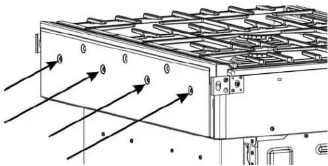
natural_image
Technical diagram of a mechanical or electrical component with directional arrows indicating flow or movement (no text or symbols present)Figure 1: Rear louver cover screw locations
-
Lift the louver cover out of the slots holding it in place. Note the slot locations for later.
-
Remove the cooktop grates.
- Remove the screws holding the trim (five screws on the back and one screw on each end). Save these screws for installation of the Low Backguard.
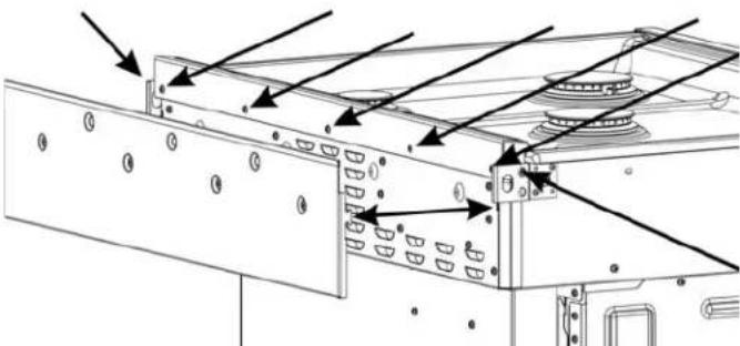
natural_image
Technical diagram of a server rack with mounting holes and ventilation slots (no text or labels)Figure 2: Trim screw locations (louver cover removed)
- Rotate the trim forward, slide slightly to the front, and lift it off.
- Place the Low Backguard in position A (See Figure 3: Low Backguard placement) and then move it to position B (engaging the alignment device 1) (the appearance of the devices may not be exactly as shown). Rotate the Low Backguard to a vertical position, aligning hole 2 with the holes at 3 on both sides of the range.
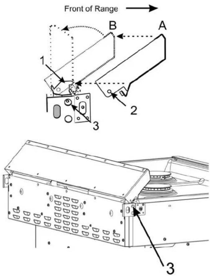
text_image
Front of Range 1 2 3 A BFigure 3: Low Backguard placement
- Secure the Low Backguard with one screw at each end (through holes 2 and 3) and hold the Low Backguard in a vertical position while securing the five screws in the back.
- Place the rear louver cover into its slots and secure with four screws.
- Replace the cooktop grates.
- If necessary, have a qualified service person reattach electrical or gas connections.
- Slide the range back into position.
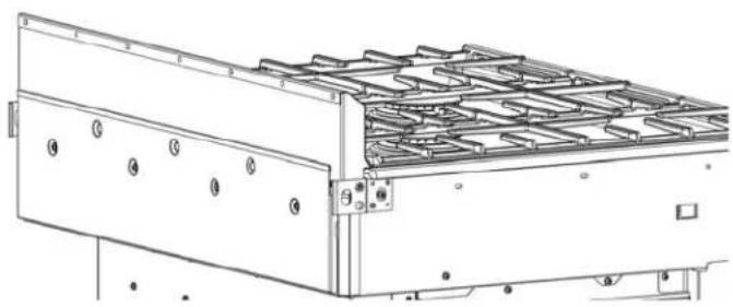
natural_image
Technical line drawing of a mechanical or electrical component with mounting holes and internal grid structure (no text or symbols)Figure 4: Low Backguard in position
Procedure for an Electric or Induction Slide-In-Range (Low Backguard, Electric and Induction HEBZS301)
Tools Needed
- Torx T20 screwdriver
• g l o v e s
Preparation
IMPORTANT!
Can you slide the range out enough to have access to the rear and side rear trim screws?
- If you can slide the range out, continue with the procedure,
- If you cannot slide the range out, contact a qualified service person to disconnect the electrical connections that prevent the range from being pulled out before continuing with the procedure.
- Read the Tip Over Warning in the Safety Section of this manual. Be aware of this when the range has been pulled out of the anti-tip bracket for this installation.
Procedure
- Confirm that the range is cool enough to be comfortably touched at the rear.
- Slide the range out enough to access the trim mounting screws.
- Remove the screws holding the trim (five screws on the back and one screw on each end). Save these screws for installing the Low Backguard.
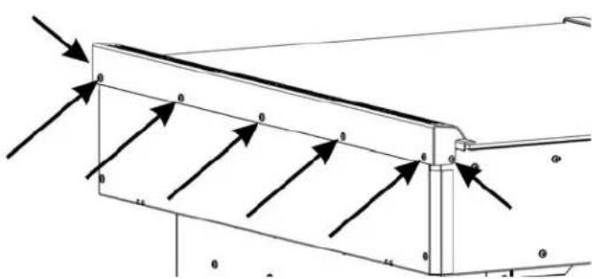
text_image
Technical diagram showing a structural beam with multiple supports and load arrows, labeled with dimension 'a' and 'b'.Figure 5: Trim screw locations
- Lift the trim off.
- Lower the Low Backguard into place, aligning the holes at 1 with the holes at 2 on both sides of the range.
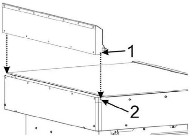
text_image
Technical diagram showing two labeled components (1 and 2) of a structural assembly with dashed alignment lines.Figure 6: Low Backguard placement
- Secure the Low Backguard with one screw at each end and then hold the Low Backguard in a vertical position while securing the 5 screws in the back.
- If necessary, have a qualified service person reattach the electrical connections.
- Slide the range back into position.
- End of procedure.
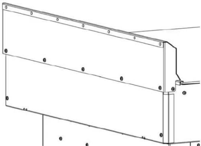
natural_image
Technical line drawing of a structural frame with supports and mounting points (no text or symbols)Figure 7: Low Backguard in position
natural_image
Silhouette of a person pushing a large object upward (no text or symbols)Bonne technique de manutention
text_image
Black-and-white illustration showing a hand holding a car with a 'no' symbol and a checkmark, suggesting no violation or rejection.natural_image
Technical diagram of a heat exchanger or cooling unit with directional arrows indicating flow (no text or labels present)natural_image
Technical diagram of a mechanical assembly with mounting holes and structural elements (no text or symbols)text_image
Technical diagram of a device with labeled components and numbered partsnatural_image
Technical line drawing of a mechanical assembly with mounting holes and internal channels (no text or symbols)text_image
Technical diagram showing a structural beam with multiple supports and directional arrows indicating force or displacement vectors.Figure 5: Emplacements des vis de la garniture
text_image
Technical diagram of a mechanical assembly with labeled components 1 and 2natural_image
Technical line drawing of a mechanical component or enclosure with mounting brackets and mounting holes (no text or symbols)Figure 7: Dosseret bas en position