Outdoor Living Foundation ODFS81SYS - Speaker Martin Logan - Free user manual and instructions
Find the device manual for free Outdoor Living Foundation ODFS81SYS Martin Logan in PDF.


User questions about Outdoor Living Foundation ODFS81SYS Martin Logan
0 question about this device. Answer the ones you know or ask your own.
Ask a new question about this device
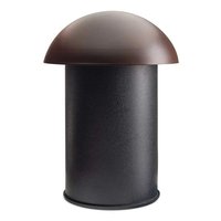
Download the instructions for your Speaker in PDF format for free! Find your manual Outdoor Living Foundation ODFS81SYS - Martin Logan and take your electronic device back in hand. On this page are published all the documents necessary for the use of your device. Outdoor Living Foundation ODFS81SYS by Martin Logan.
USER MANUAL Outdoor Living Foundation ODFS81SYS Martin Logan
natural_image
Illustration of a mushroom-shaped container and several small kitchen utensils arranged in rows (no text or symbols)OUTDOOR LIVING ^TM SERIES
by MARTIN LOGAN®
Register your warranty online at www.MartinLogan.com.
TABLE OF CONTENTS
Overview....3
Outdoor Living ^™ Foundation Music System ..... 3
Contents of the System 3
Additional Required Components (Sold Separately) . . . 3
Required Tools 3
Power 3
Planning the System Layout .... 4
Cable Recommendations .... 5
Installation Considerations .... 5
Wiring & Speaker Installation ..... 6
Stereo Setup Using 4 Conductor Burial Cable & Amplifier (Option 1) 6
Stereo Setup Using 4 Conductor Burial Cable & Amplifier (Option 2) 7
Mono Setup Using 2 Conductor Burial Cable & Amplifier (Option 3) 8
Preparing the 4 Conductor Burial Cable (For Stereo Setup)....9
Preparing the 2 Conductor Burial Cable (For Mono Setup)....10
Attaching Ground Stake to Speaker & Installation . . . 11
Cable Connections from Speaker to RED (+) and BLACK (-) Burial Cable 12
Cable Connections from Speaker to WHITE (+) and GREEN (−) Burial Cable 12
Cable Connections from Subwoofer to Burial Cable....13
Test System 14
To Avoid Speaker Damage ..... 14
Listening Outdoors....14
Limited Warranty....15
natural_image
Empty white image with corner brackets (no text or symbols)OVERVIEW
MartinLogan Outdoor Living™ Foundation Music System
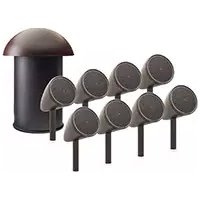
The MartinLogan Outdoor Living Foundation Music System includes 8 premium all-season outdoor speakers and 1 all-season in-ground subwoofer ideal for backyards ranging from 2,000 to 3,000 sq. ft.
Made of durable UV treated ABS plastic and thick high-density polyethylene, the Outdoor Living Foundation Music System can endure the elements while providing years of trouble-free service.
While installation is relatively easy, MartinLogan's Outdoor Living Foundation Music System is designed to be installed by your authorized MartinLogan dealer.
natural_image
Simple line drawing of a mushroom-shaped container and eight identical microphones arranged in rows (no text or symbols)WARNING!

- ACCOUNT FOR POTENTIAL ELECTRICAL, GAS, BURIED CABLES, PLUMBING OR OTHER OBSTACLES BEFORE DIGGING.

- MANY LOCALITIES FORBID DIGGING WITHOUT PRIOR NOTIFICATION. CONTACT LOCAL AUTHORITIES BEFORE INSTALLATION.

- READ AND FOLLOW ALL INSTRUCTIONS BEFORE BEGINNING.
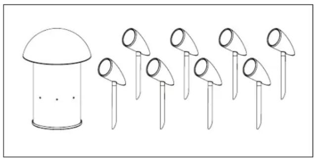
Contents of the System:
• (8) Speakers with Mounting Stakes
• (1) In-Ground Subwoofer with Canopy
• (20) Silicone-Filled Wire Connectors
Additional Required Components (Sold Separately):
- Burial Speaker Cable
- Wire Ties (Optional)
Required Tools:
- Shovel
- Cable Strippers
Power
Any 8 ohm stereo amplifier (for Stereo Setup) or Any 4 ohm mono amplifier (for Mono Setup)
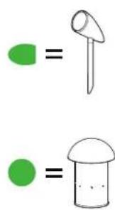
The MartinLogan Outdoor Living Foundation Music System is designed to deliver seamless, and evenly distributed sound coverage in an 'open air' environment. The following illustration shows how a daisy chain of satellite speakers and a subwoofer should be strategically placed to create even, balanced coverage around the outdoor environment. The satellite speakers should be spaced from 6 to 10 feet (2.4 - 3 meters) apart for optimal coverage. With a tighter spacing, more satellites will be required to fill out an area, but with the advantage of more consistent coverage and volume levels across the intended entertainment area.
To achieve the best balance between the satellites and subwoofer, the subwoofer should be placed as close to the center of the satellites as possible. Keep in mind that this
is simply a suggestion and that your unique environment may dictate otherwise. If more bass is desired, placing the subwoofer near a wall or other solid surface will greatly reinforce the low bass frequencies.
Checklist:
□ Identify the location.
☐ Determine the positioning of the satellite speakers and subwoofer.
☐ Dig the trench according to satellite speakers and subwoofer to be installed.
☐ The trench should be 6" - 8" deep.
text_image
Simple math illustration showing two green shapes: a green circle with a stick and a white circle with a mushroom, both equal to their respective green circles.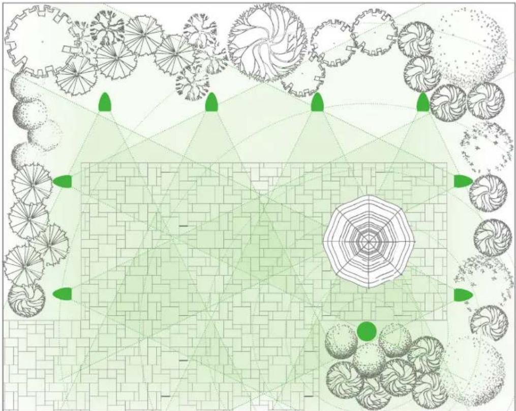
natural_image
Top-down architectural or engineering diagram showing a grid layout with circular patterns, radial lines, and green geometric elements (no text or symbols)CABLE RECOMMENDATIONS
We strongly recommend using burial-rated cable (not included) when installing the Outdoor Living Foundation Music System. In addition, it's critical to use the proper speaker cable gauge. Please review the chart below.
| CABLE GAUGE CHART | |
| Cable Gauge Distance | |
| 18 Gauge Up to 100 feet (30 meters) | |
| 16 Gauge Up to 150 feet (45 meters) | |
| 14 Gauge Up to 200 feet (61 meters) | |
| 12 Gauge Up to 400 feet (122 meters) |
INSTALLATION CONSIDERATIONS
There are a few considerations before you start digging a trench:
- Ensure that your ENTIRE system is tested prior to installation.
- Ensure that the proposed area is easily accessed and that the area is not prone to flooding, standing water or where the speakers and subwoofer can be easily damaged, kicked or struck.
- Consider overall landscape/garden design and positioning in relation to the listening area.
WIRING & INSTALLATION
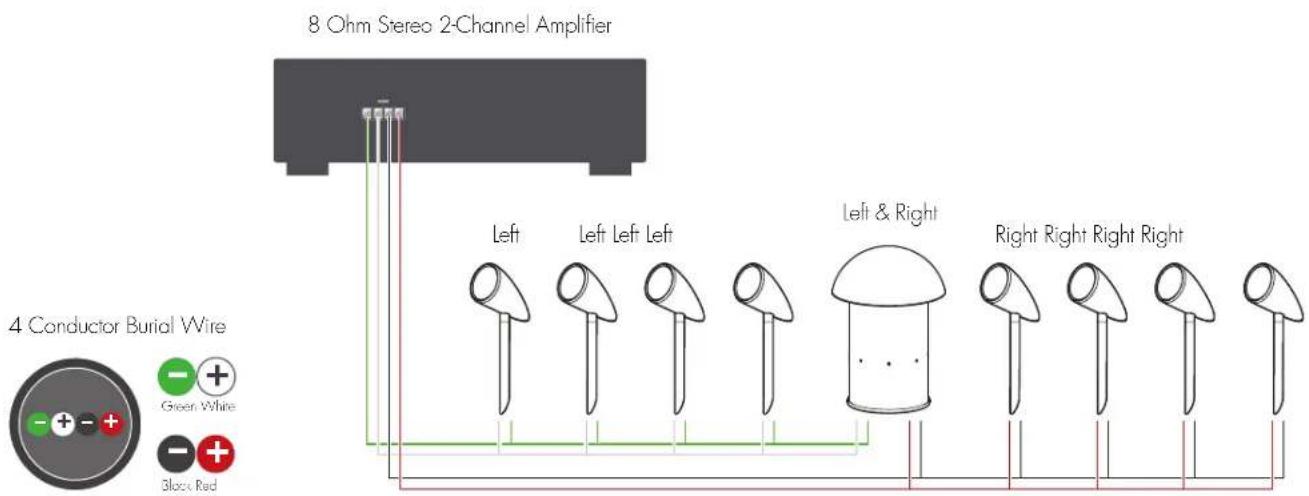
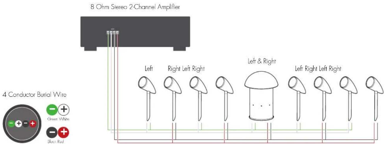
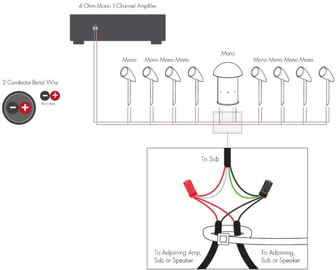
The satellite speakers included in this system individually present a 32 ohm load to the amplifier. When 4 of them are connected on each amplifier channel in parallel, the load to the amplifier is approximately 8 ohms. The nominal impedance of the subwoofer is 8 ohms per channel. The satellites and subwoofer feature optimized internal crossovers so that the subwoofers impedance is not combined with the satellites. The overall load presented to your amplifier by the combined system of 8 satellites and 1 subwoofer will be around 8 ohms nominal per channel.
With these considerations in mind, multiple system wiring possibilities are possible. The following diagrams are simple, and safe examples of wiring the system to a traditional 8 ohm stereo amplifier. If using an alternative wiring or amplification configuration, please take care to ensure that the impedance presented to your amplifier is within its published specifications. Failure to adhere to the above guidance could result in damage to the speakers and/or the amplifier which MartinLogan will not take responsibility for and will not be covered under warranty.
Stereo Setup Using 4 Conductor Burial Cable & Amplifier (Option 1)
text_image
8 Ohm Stereo 2-Channel Amplifier 4 Conductor Burial Wire Green White Black Red Left Left Left Left Left & Right Right Right Right RightWIRING & INSTALLATION (CONT'D)
Stereo Setup Using 4 Conductor Burial Cable & Amplifier (Option 2)
text_image
8 Ohm Stereo 2-Channel Amplifier 4 Conductor Burial Wire Green White Black Red Left Right Left Right Left & Right Left Right Left RightMono Setup Using 4 Conductor Burial Cable & Amplifier (Option 3)
text_image
4 Ohm Mono 1-Channel Amplifier Mono Mono Mono Mono Mono Mono Mono Mono Mono Mono 2 Conductor Burial Wire Block Red To Sub To Adjoining Amp, Sub or Speaker To Adjoining, Sub or SpeakerWIRING & INSTALLATION (CONT'D)
Preparing the 4 Conductor Burial Cable (For Stereo Setup)
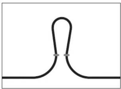
- Starting with the first speaker and every speaker/sub that comes after, create a loop approximately 6" in length.
natural_image
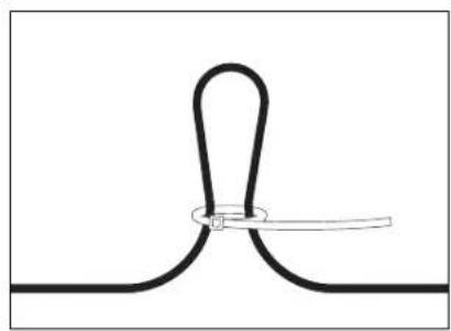
Pure diagram of a symmetrical U-shaped line with two small dots at the center (no text or symbols)- Recommended: Use a wire tie (not included) to keep the wire loop intact and it will act as a strain relief.
natural_image
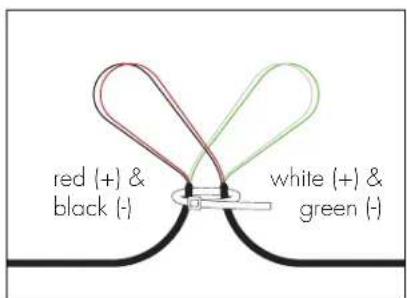
Pure diagram of a symmetrical shape with a central oval and a horizontal bar, no text or symbols present.- Use a round cable stripper to remove the outside protective cable jacket to expose the four color-coded wires. Separate the wire loops as shown.
text_image
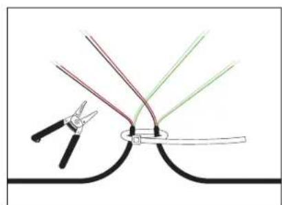
red (+) & black (-) white (+) & green (-)- Cut the red (+) and black (-) OR white (+) and green (-) wires with cable strippers and strip off 1 inch (25.4 mm) of insulation to expose the bare wire conductor.
natural_image
Illustration of a pair of pliers cutting through a curved wire with colored wires (no text or symbols)Preparing the 2 Conductor Burial Cable (For Mono Setup)
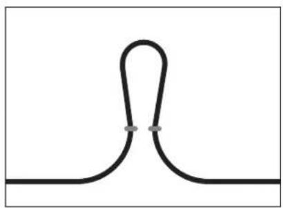
- Starting with the first speaker and every speaker/sub that comes after, create a loop approximately 6" in length.
natural_image
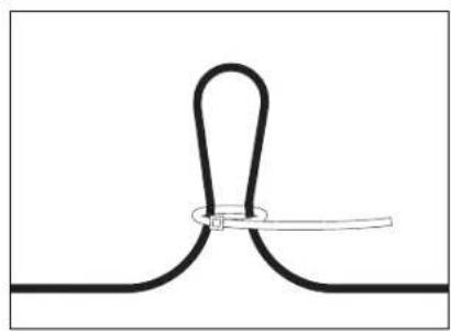
Pure diagram of a symmetrical U-shaped line with two small dots, no text or symbols present- Recommended: Use a wire tie (not included) to keep the wire loop intact and it will act as a strain relief.
natural_image
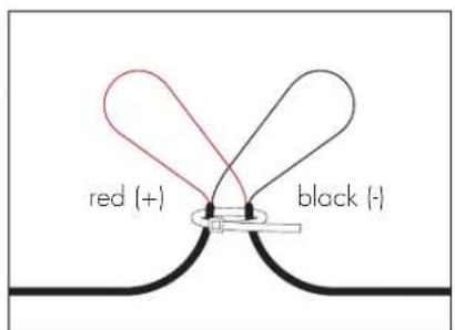
Pure diagram of a symmetrical shape with a central oval and a horizontal line, no text or symbols present.- Use a round cable stripper to remove the outside protective cable jacket to expose the two color-coded wires. Separate the wire loops as shown.
text_image
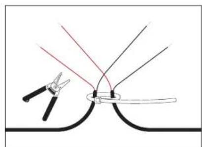
red (+) black (-)- Cut the red (+) and black (-) wires with cable strippers and strip off 1 inch (25.4mm) of insulation to expose the bare wire conductor.
natural_image
Diagram showing a pair of pliers cutting through a curved tool, with no text or symbols present.WIRING & INSTALLATION (CONT'D)
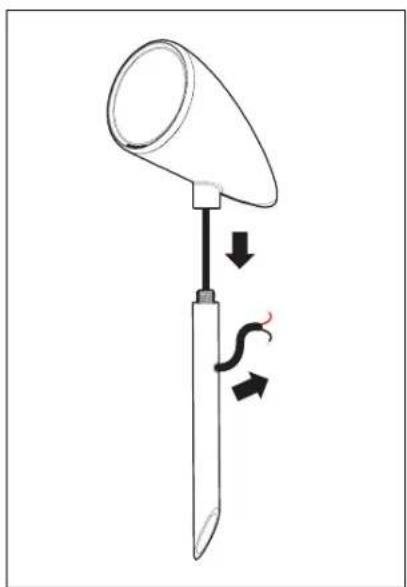
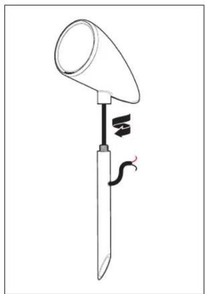
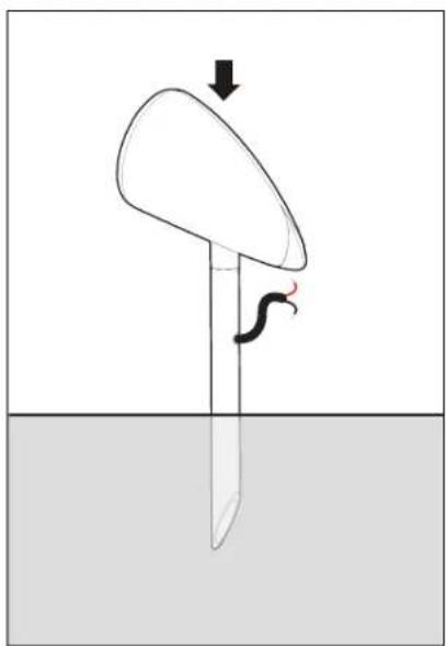
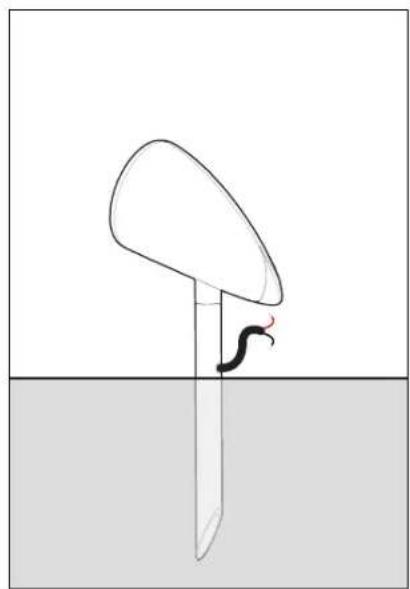
Attaching Ground Stake to Speaker & Installation
- Thread the speaker's wiring down through the ground stake and out of the wiring hole as shown.
natural_image
Diagram of a medical or laboratory device with a funnel and lever, showing internal force and motion arrows (no text or symbols)- To attach the speaker to the ground stake, hand thread the speaker to the ground stake.
natural_image
Simple line drawing of a medical or laboratory instrument with a funnel and scale, no text or symbols present.- By hand, push the speaker assembly into the ground. CAUTION: DO NOT use a hammer.
natural_image
Diagram of a fish being held by a rod over water, with an arrow indicating direction (no text or symbols)- The speaker is now installed. The next step is wiring, go to the next page for instructions.
natural_image
Simple line drawing of a fish jumping from a curved object above a surface (no text or symbols)Cable Connections from Speaker to RED (+) AND BLACK (-) Burial Cable
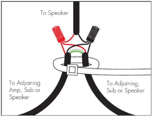
Before you start wiring, please refer to the wiring setup options on pages 6 to 8. Combine and twist (clockwise) the Red wire (as shown in the diagram) from a speaker or subwoofer to the Red wires from the burial cable. Secure these three wires using the provided silicone-filled wire connector; Repeat this procedure for the Black wires. NOTE: You may have to cut some of the speaker cable emanating from the speaker to a more manageable size.
text_image
To Speaker To Adjoining Amp, Sub or Speaker To Adjoining, Sub or SpeakerCable Connections from Speaker to WHITE (+) AND GREEN (-) Burial Cable
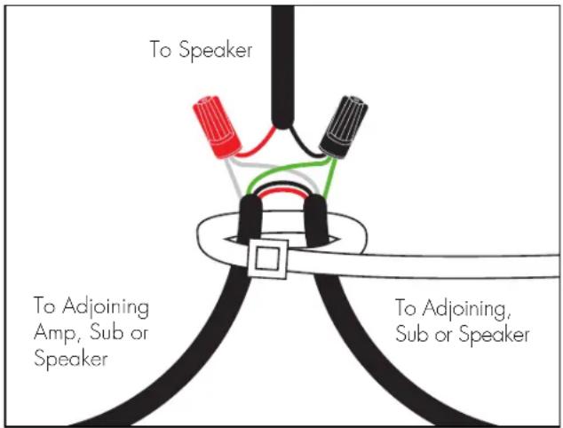
Before you start wiring, please refer to the wiring setup options on pages 6 to 8. Combine and twist (clockwise) the Red wire (as shown in the diagram) from a speaker or subwoofer to the White wires from the burial cable. Secure these three wires using the provided silicone-filled wire connector; Repeat this procedure for the Black and Green wires. NOTE: You may have to cut some of the speaker cable emanating from the speaker to a more manageable size.
text_image
To Speaker To Adjoining Amp, Sub or Speaker To Adjoining, Sub or SpeakerWIRING & INSTALLATION (CONT'D)
Cable Connections from Subwoofer to Burial Cable
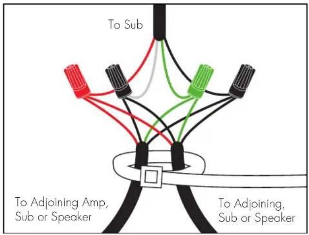
Before you start wiring, please refer to the wiring setup options on pages 6 to 8. Combine and twist (clockwise) the Red wire (as shown in the diagram) from a speaker or subwoofer to the Red wires from the burial cable. Secure these three wires using the provided silicone-filled wire connector; Repeat this procedure for the Black, Green and White wires. NOTE: You may have to cut some of the speaker cable emanating from the subwoofer to a more manageable size.
text_image
To Sub To Adjoining Amp, Sub or Speaker To Adjoining, Sub or SpeakerTEST SYSTEM
After all satellites and subwoofer connections are completed, connect the wires to your receiver or amplifier.
IMPORTANT: Be sure not to let any stray '+' and '-' strands touch each other. Touching strands will cause a short circuit that could damage your amplifier.
Turn your receiver or amplifier 'On' and test the system with your favorite music. If your system is operating properly, refill the wire trench and enjoy your new speakers.
TO AVOID SPEAKER DAMAGE
Contrary to popular belief, most speaker damage and distortion occurs from using an amplifier with too little power. The more available power an amplifier has, the higher the threshold becomes before clipping occurs (outputting damaging distortion), effectively raising the useable volume of the system. Of course, going overboard with power can allow the listener to exceed the mechanical limits of the speakers and result in speaker damage and distortion. However, when used appropriately, a more powerful amplifier can reduce the risk of distortion or speaker damage as the amplifier will be able to continuously operate within
its intended "safe range" during normal playback of the system.
If your speakers begin to sound harsh or grating, or if you hear the bass breaking up, turn the volume down immediately or you will damage your speakers! This type of damage constitutes abuse and is not covered under warranty.
Tone controls and equalizers can demand even more power from an amplifier, lowering the point at which it produces clipping distortion. Use them sparingly, if at all, and avoid using them when listening at loud levels.
LISTENING OUTDOORS
For areas larger than 3,000 sq. ft., we recommend using multiple MartinLogan Outdoor Living Foundation systems. Please note that powering multiple Outdoor Living Foundation systems may require additional amplification to properly integrate. Please consult your dealer for guidance on amplifier capability and selection. Using more speakers ensures that sound is not only more evenly distributed, but
also allows the system to be more easily heard at lower listening levels. By doing this, demand on the amplifier is reduced and neighbors are not disturbed. Think of it this way: When lighting a large outdoor area, using multiple floodlights on a dimmer set to a low setting is far more effective than using a single floodlight with the dimmer set to high.
LIMITED WARRANTY
The MartinLogan® Outdoor Living Foundation Music System is warranted to be and remain free of manufacturing and/or material defects for a period of three (3) years from the date of original purchase. Within the time period specified, repair, replacement or adjustment of parts for manufacturing and/or material defects will be free of charge to the original owner. Thermal or mechanical abuse/misuse is not covered under warranty.
Limitations:
- Warranty begins on date of original retail purchase from an Authorized MartinLogan® Dealer only. It is not transferable.
- Warranty applies to product in normal residential use only. If product is subjected to any of the conditions outlined in the next section, warranty is void.
- Warranty does not apply if the product is used in professional or commercial applications.
- Warranty also excludes normal cosmetic deterioration caused by environmental conditions.
Warranty is Void if:
- The product has been abused (intentionally or accidentally).
- The product has been used in conjunction with unsuitable or faulty equipment.
- The product has been subjected to damaging signals, derangement in transport, mechanical damage or any abnormal conditions.
- The product (including cabinet) has been tampered with or damaged by an unauthorized service facility.
- The serial number has been removed or defaced.
Owner Responsibilities:
- Provide normal/reasonable operating care and maintenance.
- Provide or pay for transportation charges for product to service facility.
- Provide proof of purchase (your sales receipt given at time of purchase from your Authorized MartinLogan® Dealer must be retained for proof-of-purchase date).
Should servicing be required, contact your nearest Authorized MartinLogan® Dealer, MartinLogan Ltd. or Import Distributor (outside the U.S. and Canada) to arrange, bring in or ship prepaid, any defective unit. Visit our website, www.martinlogan.com for more information.
Martinlogan Ltd. reserves the right to improve the design of any product without assuming any obligation to modify any product previously manufactured.
This warranty is in lieu of all other warranties expressed or implied, of merchantability, fitness for any particular purpose and may not be extended or enlarged by anyone. In no event shall MartinLogan Ltd., their agents or representatives be responsible for any incidental or consequential damages. Some jurisdictions do not allow limitation of incidental or consequential damages, so this exclusion may not apply to you.
Retain this manual and your sales receipt for proof of warranty term and proof of purchase.
NOTES
NOTES
OUTDOOR LIVING™
FOUNDATION
SYSTÈME D'ENCEINTES MUSICALES D'EXTÉRIEUR
natural_image
Illustration of a mushroom-shaped container and several stylized kitchen utensils (no text or symbols)SÉRIE OUTDOOR LIVING™
par MARTIN LOGAN®
natural_image
Illustration of a mushroom-shaped container and several small kitchen utensils arranged in rows (no text or symbols)AVERTISSEMENT

- TENIR COMPTE DES ÉVENTUELS OBSTACLES ÉLECTRIQUES, DE GAZ, DE CÂBLES ENTERRÉS, DE PLOMBERIE OU AUTRES AVANT DE CREUSER.

- DE NOMBREUSES LOCALITÉS INTERDISENT DE CREUSER SANS NOTIFICATION PRÉALABLE. CONTACTEZ LES AUTORITÉS LOCALES AVANT L'INSTALLATION.

- LISEZ ET SUIVEZ TOUTES LES INSTRUCTIONS AVANT DE COMMENCER L'INSTALLATION.