
OD5008 - Sensor IFM - Free user manual and instructions
Find the device manual for free OD5008 IFM in PDF.



| Product type | Color sensor (color detector) |
| Brand | IFM |
| Model | OD5008 |
| Dimensions (L x H x D) | 96 x 80 x 28 mm |
| Power supply | 24 V DC |
| Detection principle | Direct reflection or retroreflective |
| Typical range | 12.5 mm (direct reflection) |
| Number of switching outputs | 1 or 3 depending on version |
| Response time | < 0.2 ms |
| Synchronization input (AT) | 12 V < AT < U Vmax to deactivate, ≤2 V to activate |
| External programming input (ET) | 0.5 ms pulse to program reference color |
| Color tolerance adjustment | Rotary switch from 1 (low) to 5 (high) |
| Indicators | Power LED, function LED (Out/OK) |
| Teach (learning) | Teach button to store a reference color |
| Housing material | Not specified (plastic or metal) |
| Protection rating | Not specified (IP67 probable) |
| Connection | M12x1 connector, 5-pin (1 output) or 8-pin (3 outputs) |
| Operating temperature | Not specified (typ. -25 to 70 °C) |
| Mounting | Non-contact, perpendicular or tilted 10-30° for shiny objects |
| Maintenance | Clean the optical window with a soft cloth |
| Safety | Disconnect power before any connection |
Frequently Asked Questions - OD5008 IFM
User questions about OD5008 IFM
0 question about this device. Answer the ones you know or ask your own.
Ask a new question about this device
Download the instructions for your Sensor in PDF format for free! Find your manual OD5008 - IFM and take your electronic device back in hand. On this page are published all the documents necessary for the use of your device. OD5008 by IFM.
USER MANUAL OD5008 IFM
natural_image
Simple line drawing of a rectangular object with a bolt and three circular holes, no text or symbols present.Functions and features
The colour sensor detects coloured objects and materials without contact in diffuse-reflection or retro-reflective mode.
Mounting
natural_image
Pure mechanical diagram showing a lever mechanism with arrows and circles, no text or symbols present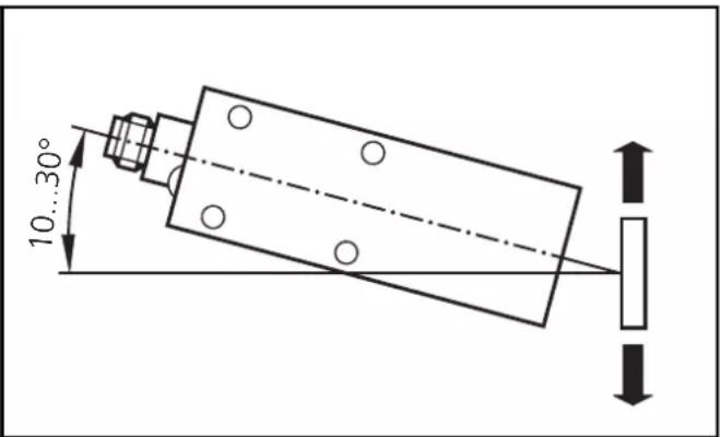
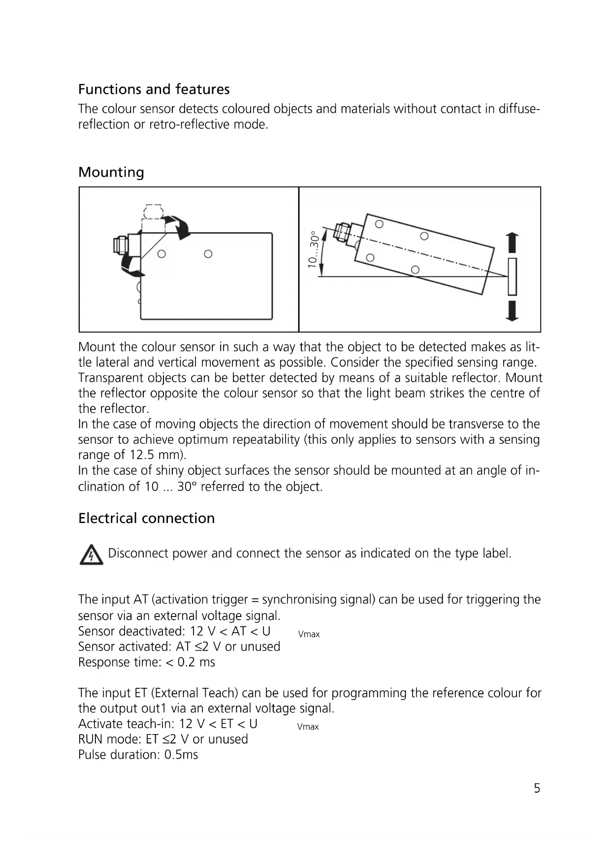
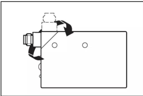
Mount the colour sensor in such a way that the object to be detected makes as little lateral and vertical movement as possible. Consider the specified sensing range.
Transparent objects can be better detected by means of a suitable reflector. Mount the reflector opposite the colour sensor so that the light beam strikes the centre of the reflector.
In the case of moving objects the direction of movement should be transverse to the sensor to achieve optimum repeatability (this only applies to sensors with a sensing range of 12.5 mm).
In the case of shiny object surfaces the sensor should be mounted at an angle of inclination of 10 ... 30° referred to the object.
Electrical connection

Disconnect power and connect the sensor as indicated on the type label.
The input AT (activation trigger = synchronising signal) can be used for triggering the sensor via an external voltage signal.
Sensor deactivated: 12 V < AT < U v_max
Sensor activated: AT ≤2 V or unused
Response time: < 0.2 ms
The input ET (External Teach) can be used for programming the reference colour for the output out1 via an external voltage signal.
Activate teach-in: 12 V < ET < U Vmax
RUN mode: ET ≤2 V or unused
Pulse duration: 0.5ms
Controls and indicators
Setting and programming
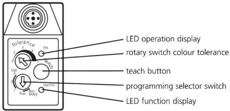
| 1 | 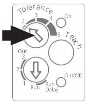 | Set the rotary switch colour tolerance (Tolerance) to the requested colour resolution.1 = small tolerance range for detecting small colour shades3 = basic setting5 = large tolerance range for detecting colour families or colour groups |
| 2 | 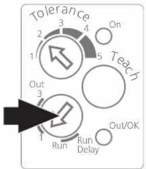 | Set the programming selector switch to the colour channel to be adjusted (switching output Out1, Out2 or Out3).For units with only one switching output set the programming selector switch to Out1. |
| 3 | 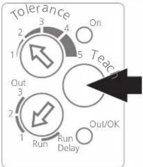 | Press the Teach button.A red light spot shows on the object.Release the Teach button, the light spot disappears. |
| 4 | 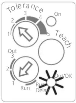 | After a successful teach-in operation the function display (Out/OK) comes on. If it flashes, the intensity is too high. Incline the sensor by 10 ... 30° and repeat the teach-in operation.If the function display is not lit, the intensity is too low. Select a lighter mark.Only for retro-reflective modeIf the function display flashes, increase the distance sensor/object or sensor/reflector or use a smaller reflector.If the function display is not lit, reduce the distance sensor/object or sensor/reflector or use a larger reflector. |
| 5 | 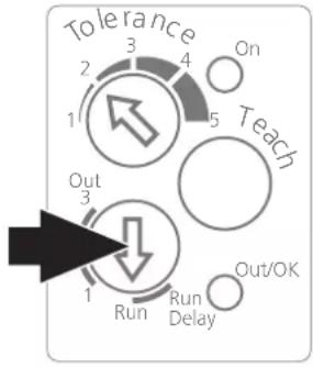 | Set the programming selector switch to Run or Run Delay (20 ms switch-off delay).For sensors with several switching outputs repeat the programming for the other switching outputs accordingly.The colour tolerance can be individually determined for each switching output.The sensor is ready for operation.If the switching output is activated, the function display is lit (Out/OK).If the tolerance setting is to be changed subsequently, programming must be made again with the tolerance setting changed. |
Programmation: 12 V < ET < U Vmax
Brand : IFM
Model : OD5008
Category : Sensor