
ELVOX EBM2 - Garage door Vimar - Free user manual and instructions
Find the device manual for free ELVOX EBM2 Vimar in PDF.
| Product type | Irreversible operator for up-and-over doors (SLAVE) |
| Brand | Vimar |
| Model | ELVOX EBM2 |
| Category | Garage door |
| Max door area | 12 m² (2 motors) |
| Max door width | 6 m (2 motors) |
| Max door height | 2.5 m |
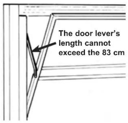
| Max lever length | 83 cm |
| Power supply | 230 V ~ 50 Hz |
| Motor voltage | 24 Vdc |
| Motor power | 55 W |
| Mains current draw | 1.2 A |
| SLAVE operator weight | 8 kg |
| Protection rating | IP44 |
| Operating temperature | -10 °C to +55 °C |
| Noise level | <70 dB |
| Recommended cycles per day | 36 |
| Adjustable opening time | 15 to 23 s |
| Main functions | Motorization, integrated LED lighting, speed adjustment, impact sensor, manual release, end position adjustment |
| Maintenance | Annual lubrication of hinges, guides and levers by specialized personnel after power cut-off |
| Safety | Photocells, safety edge, compliance EN 12453/12445, manual release, IP44 protection |
| Spare parts | Longerons (EBX1/EBX7), straight/curved levers (EBX2/EBX6), lateral joint (EBX4), cable release kit (EBS2) |
Frequently Asked Questions - ELVOX EBM2 Vimar
User questions about ELVOX EBM2 Vimar
0 question about this device. Answer the ones you know or ask your own.
Ask a new question about this device
Download the instructions for your Garage door in PDF format for free! Find your manual ELVOX EBM2 - Vimar and take your electronic device back in hand. On this page are published all the documents necessary for the use of your device. ELVOX EBM2 by Vimar.
USER MANUAL ELVOX EBM2 Vimar
Installation and operation manual
natural_image
Black metal mechanical component with mounting holes and a central hole (no visible text or symbols)EBM2
natural_image
Technical line drawing of a door frame with vertical supports and a central door (no text or symbols)COMPONENTI DA INSTALLARE SECONDO LA NORMA EN12453
natural_image
Close-up of a hand holding a small metal tool, next to a mechanical component with no visible text or symbols.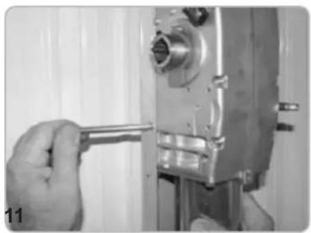
natural_image
Close-up of a hand using a wrench to adjust or install a mechanical component (no visible text or symbols)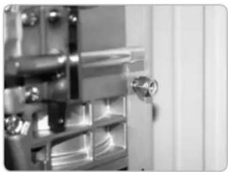
natural_image
Close-up of a metallic door with a handle and internal compartments (no visible text or symbols)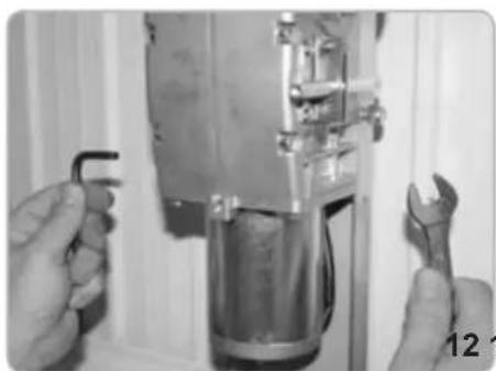
natural_image
Close-up of hands using a wrench to adjust or install a mechanical component (no visible text or symbols)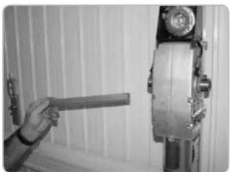
natural_image
Person holding a tool next to a mechanical device mounted on a wall (no visible text or symbols)natural_image
Close-up of a hand adjusting a metallic mechanical component with a cylindrical part inserted, no visible text or symbols.
natural_image
Close-up of hands assembling a metallic mechanical component (no visible text or symbols)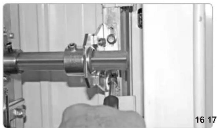
natural_image
Close-up of a hand operating a mechanical assembly with a metallic pipe and clamped components (no visible text or symbols)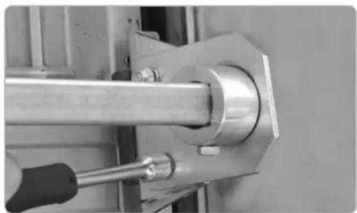
natural_image
Close-up of a mechanical assembly with a metallic rod and bolted joint (no visible text or symbols)natural_image
Close-up of a hand using a tool to adjust or install a mechanical component (no visible text or symbols)
natural_image
Close-up of a hand operating a mechanical tool with a metallic component and pipe (no visible text or symbols)
natural_image
Close-up of a gloved hand using a tool to adjust or install a mechanical component (no visible text or symbols)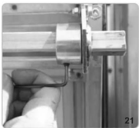
natural_image
Close-up of a hand holding a metallic mechanical component, no visible text or symbols
natural_image
Close-up of a mechanical assembly with metallic components and a numbered label '22' (no readable text or symbols)
natural_image
Close-up of a hand using a tool to adjust or install a mechanical component (no visible text or symbols)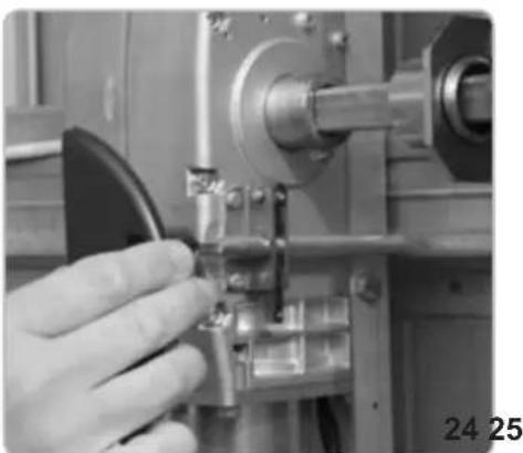
natural_image
Close-up of a hand operating a mechanical tool with a metallic component (no visible text or symbols)
natural_image
Close-up of industrial machinery components including a metallic frame and mechanical bracket (no visible text or symbols)natural_image
Interior view of a device showing internal components and wiring (no visible text or symbols)
natural_image
Technical line drawing of a mechanical housing with wheels and internal components (no text or symbols)
natural_image
Technical line drawing of a mechanical housing or enclosure component (no text or symbols)FISSAGGIO CAVO ELETTRICO LATO OPERATORE MASTER
natural_image
Close-up of a mechanical assembly with a metallic component and bolts (no visible text or symbols)
natural_image
Close-up of hands using a tool to adjust or install a mechanical component (no visible text or symbols)
natural_image
Close-up of mechanical components including a cylindrical component and a black tool, no visible text or symbolsREGOLAZIONE FINECORSA CHIUSURA

natural_image
Close-up of a mechanical device with a central square component and wiring (no visible text or symbols)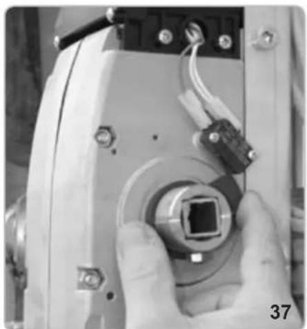
natural_image
Close-up of a hand holding a small electronic device with a central connector and wiring (no visible text or symbols)
natural_image
Close-up of a hand holding a tool interacting with an electronic device component (no visible text or symbols)FISSAGGIO CARTER
natural_image
Technical line drawing of a mechanical component with no visible text or symbols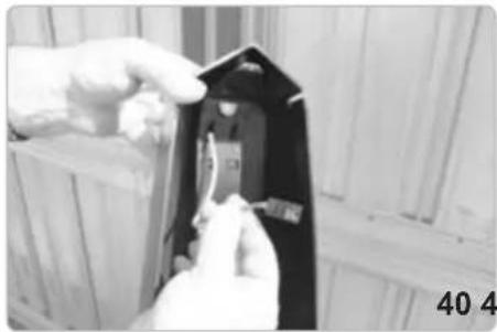
natural_image
Close-up of hands installing or adjusting a black electrical component with a small component, against a wooden background (no visible text or symbols)
natural_image
Close-up of hands holding a small electronic component with warning symbol (no readable text or symbols)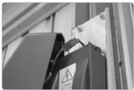
natural_image
Close-up of a black electrical component with warning symbol and safety tag, mounted on a metal frame (no readable text or symbols)
natural_image
Close-up of hands using a screwdriver to adjust or install a mechanical component (no visible text or symbols)
natural_image
Close-up of hands using a tool to adjust or install a mechanical component (no visible text or symbols)
natural_image
Person operating a mechanical device with a tool, no visible text or symbols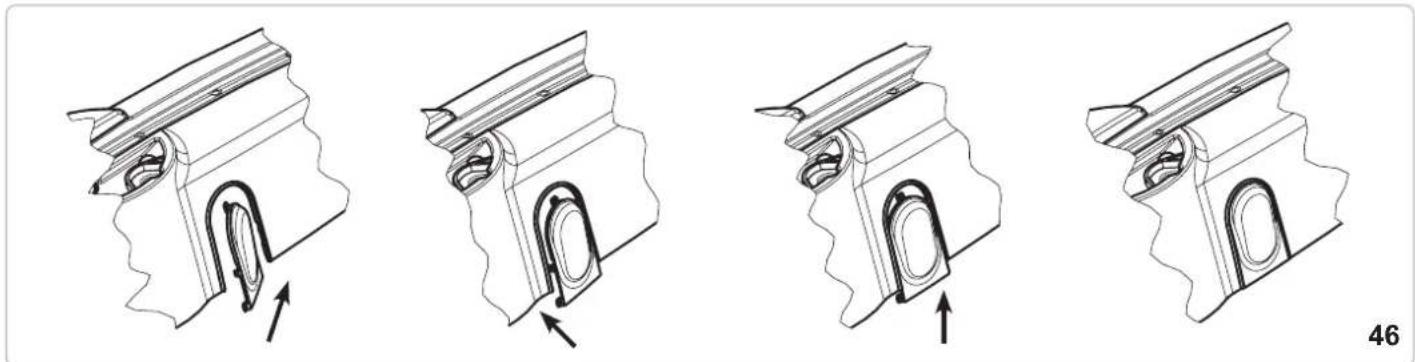
natural_image
Four technical illustrations of a mechanical component with internal channels and arrows indicating movement (no text or symbols)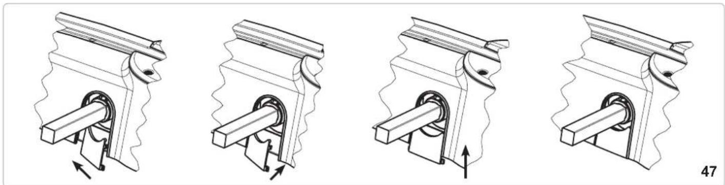
natural_image
Four technical illustrations of a mechanical piston-cranked pump mechanism, showing internal components and motion direction (no text or symbols)SBLOCCO INTERNO A MANIGLIA
natural_image
Close-up of a mechanical joint or bracket component with a labeled arrow pointing to a feature (no text or symbols visible)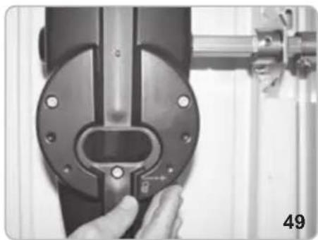
natural_image
Close-up of a hand adjusting a mechanical component with a circular housing and metal bracket (no visible text or symbols)
natural_image
Close-up of a hand using a tool to adjust or install a mechanical component, no visible text or symbols.
natural_image
Close-up of a mechanical component with metallic parts and mounting holes (no visible text or symbols)SBLOCCO A FILO
natural_image
Pure electrical circuit lines without any symbols
natural_image
Close-up of a mechanical assembly with a hand holding a tool, no visible text or symbols
natural_image
Close-up of mechanical components with bolts and a tool, no visible text or symbols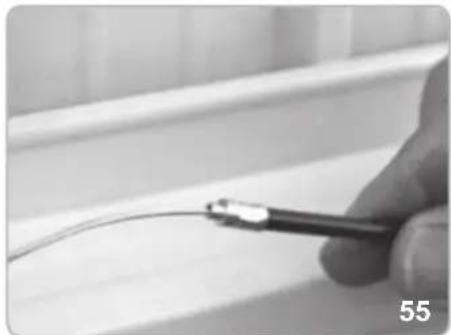
natural_image
Close-up of a hand holding a medical or laboratory tool near a white surface, no visible text or symbols
natural_image
Close-up of a hand using a screwdriver to adjust or install a metal bracket (no text or symbols visible)
natural_image
Close-up of a medical or laboratory tool with a metallic rod extending upward (no visible text or symbols)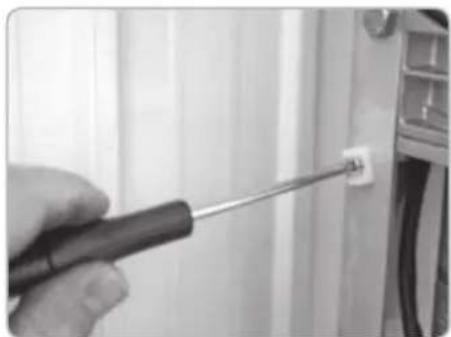
natural_image
Close-up of a hand using a screwdriver to adjust a small component on a wall (no text or symbols visible)
natural_image
Close-up of a mechanical assembly with visible wiring and components (no text or symbols)
natural_image
Close-up of a metallic pipe fitting with a hexagonal bolt inserted, mounted on a curved metal bracket (no text or symbols visible)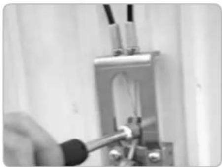
natural_image
Close-up of a hand using a tool to test or inspect a mechanical component (no visible text or symbols)
natural_image
Close-up of a mechanical or electrical component with wires and connectors, no visible text or symbols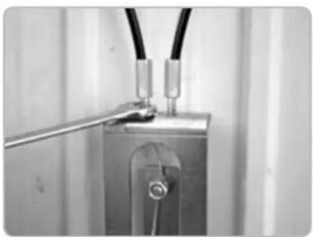
natural_image
Close-up of a metallic electrical component with wires and a metal rod inserted (no visible text or symbols)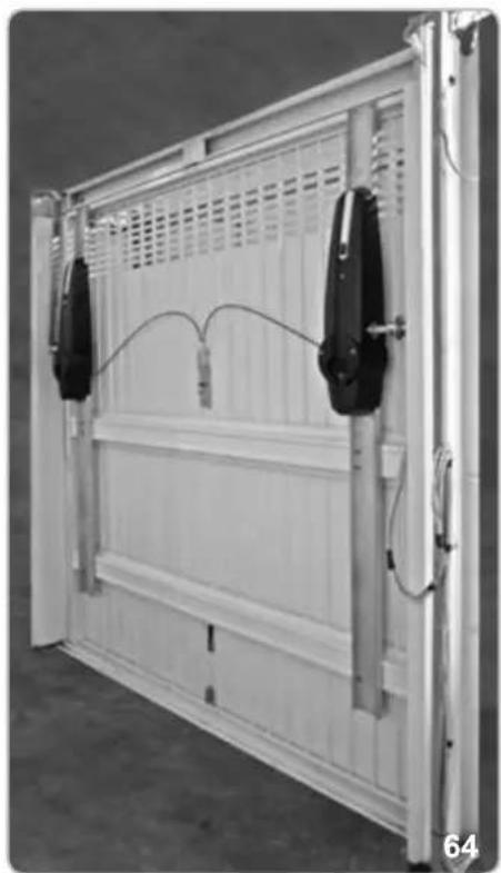
natural_image
Exterior view of a white modular storage panel with two black connectors and wiring, no visible text or symbolsnatural_image
Mechanical components including a lock, handle, key, and wrench (no text or symbols visible)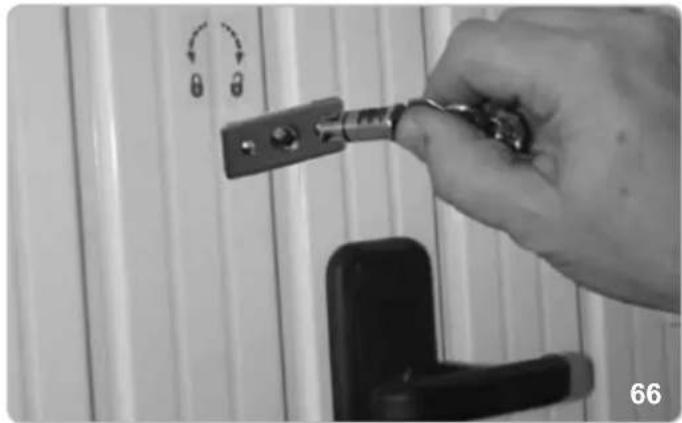
natural_image
Hand holding a key inserted into a door lock, with no visible text or symbols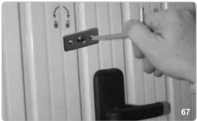
natural_image
Close-up of a hand holding a tool with a lock, against a white wall panel (no text or symbols visible)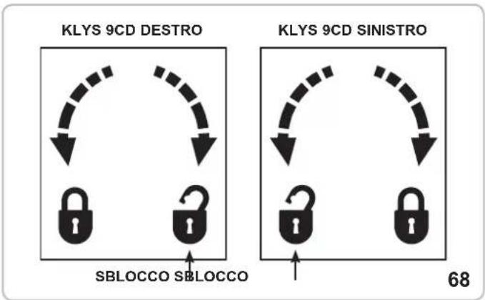
flowchart
graph TD
    A["KLYS 9CD DESTRO"] --> B["SBLOCCO"]
    C["KLYS 9CD SINISTRO"] --> D["SBLOCCO"]
    B --> E["SBLOCCO"]
    D --> F["SBLOCCO"]
    style A fill:#f9f,stroke:#333
    style C fill:#f9f,stroke:#333
    style B fill:#ccf,stroke:#333
    style D fill:#ccf,stroke:#333
    style E fill:#dfd,stroke:#333
    style F fill:#dfd,stroke:#333
ATTENZIONE!
natural_image
Simple line drawing of a cable with a U-shaped magnet and magnetic field lines (no text or symbols)cod. EBS2
LEVE CURVE
natural_image
Mechanical component with curved metallic body and mounting points (no visible text or symbols)cod. EBX6
natural_image
Collection of metal hardware components including a lock, handle, key, and lever (no text or symbols visible)cod. EBS3
LAMPEGGIATORE

natural_image
Close-up of a translucent, oval-shaped object with striped texture, possibly a decorative or mechanical component (no text or symbols visible)cod. ELA1/L
CONTENITORE CON BATTERIE
natural_image
Three electronic devices with visible wiring and connectors, no text or symbols presentcod. EBB1
FOTOCELLULE

natural_image
Two black rectangular electronic components with reflective surfaces, isolated on white background (no text or symbols)cod. EFA1
CARICA BATTERIE KLYS 9CD 24 V
natural_image
Electronic circuit board with labeled components (F1, F15A) and connectors, no readable text or symbols beyond labelscod. ECB3
SELETTORE A CHIAVE
natural_image
Illustration of a smiling computer monitor with a small figure pointing at it (no text or symbols)cod. EDS1
TELECOMANDO

natural_image
White electronic device labeled 'EDVAX' with two circular buttons and a cord, shown against a plain white background (no text beyond label)cod. ETR5
KEEP THESE INSTRUCTIONS WITH CARE
1^ - If it is not forecast in the electric gearcase, install a switch of magnetothermic type upstream, (omni polar with minimum port of the contacts of 3mm) with a check of conformity to the international standards. Such devise must be protected against the accidental lockup (for example by installing inside a locked board).
2° - For the section and the type of the cables ELVOX advices to use a cable of H05RN-F type with 1,5 sqmm minimum section and, however, to keep to the IEC 3120 and installation standards in force in your country.
3° - Positioning of a possible couple of photoelectric cells: the radius of the photoelectric cells must be at a height of no more than 70 cm from the ground and at a distance not superior to 20 cm from the motion plane of the door. Their correct working must be verified at the end of the installation in accordance with point 7.2.1 of the EN 12445.
4^ - To fulfil the limits set by EN 12453, and in case the peak force exceeds the normative limit of 400N it is necessary to have recourse to the active presence survey on the whole height of the door (up to max 2,5m ) - The photoelectric cells, in this case, must be applied to the outside and the inside to a distance from the plan of movement of the door not advanced to 20cm , every 60 + 70cm for all the height of the door until to a maximum of 2,5m (EN 12445 point 7.3.2.1)
N.B.: The earthing of the system is obligatory.
The data described in this handbook are purely a guide.
ELVOX reserves the right to change them in any moment.
Carry out the system in the respect of the standards and laws in force.
IMPORTANT SAFETY INSTRUCTIONS
FOR THE INSTALLATION
ATTENTION - THE INCORRECT INSTALLATION CAN CAUSE SERIOUS DAMAGES
FOLLOW ALL INSTALLATION INSTRUCTIONS
1° - This handbook is exclusively addressed to the specialized personnel who knows the constructive criteria and the protection devices against the accidents for motorized gates, doors and main doors (follow the standards and the laws in force).
2^ - The installer will have to issue a handbook to the final user in accordance with the 12635.
3^ - The installer will have to put the tags warning against the entrapping dangers near the controls and the horizontally pivoted door.
4° - Check frequently the system, in particular cables, springs and supports to find out possible unbalances, wear signs or damages. The final user must not operate electrically the horizontally pivoted door if this needs maintenance or repair, since a failure in the installation or a non correctly balanced barrier can provoke wounds.
5° - Before proceeding with the installation, the installer must forecast the risks analysis of the final automatized closing and the and the safety of the identified dangerous points (Following the standards EN 12453/EN 12445).
6° - Before installing the motion motor, the installer must verify that the door is in good mechanical conditions and that it adequately opens and closes.
7^ - The installer must install the member for the manual release at a height inferior to 1,8m .
8° - The installer will have to remove possible impediments to the motorized motion of the door (eg. Door bolts, sliding bolts, door locks etc.)
9° - The installer will permanently have to put the tags warning against the deflection on a very visible point or near possible fixed controls.
10^ - The wiring harness of the different electric components external to the operator (for example photoelectric cells, flashlights etc.) must be carried out according to the EN 60204-1 and the modifications to it done in the point 5.2.2 of the EN 12453.
11° - Keep the automatism controls (push-button panel, remote control etc.) out of the children way. The controls must be placed at a minimum height of 1,5 m from the ground and outside the range of the mobile parts.
12° - Before carrying out any installation, regulation or maintenance operation of the system, take off the voltage by operating on the special magnetothermic switch connected upstream.
13° - At the end of the installation, the installer will have to make sure that the parts of the door do not encumber streets or public sidewalks.
14^ - At the end of the installation, the installer will have to make sure that the motion motor prevents or blocks the opening motion when the door is loaded with a 20kg weight, fixed in the middle of the inferior edge of the door.
THE ELVOX COMPANY DOES NOT ACCEPT ANY RESPONSIBILITY for possible damages caused by the non observance during the installation of the safety standards and of the laws in force at present.
Directive 2002/96/EC (WEEE)
The crossed-out wheelie bin symbol marked on the product indicates that at the end of its useful life, the product must be handled separately from household refuse and must therefore be assigned to a differentiated collection centre for electrical and electronic equipment or returned to the dealer upon purchase of a new, equivalent item of equipment.
The user is responsible for assigning the equipment, at the end of its life, to the appropriate collection facilities.
Suitable differentiated collection, for the purpose of subsequent recycling of decommissioned equipment and environmentally compatible treatment and disposal, helps prevent potential negative effects on health and the environment and promotes the recycling of the materials of which the product is made. For further details regarding the collection systems available, contact your local waste disposal service or the shop from which the equipment was purchased.

Risks connected to substances considered as dangerous (WEEE).
According to the WEEE Directive, substances since long usually used on electric and electronic appliances are considered dangerous for people and the environment. The adequate differentiated collection for the subsequent dispatch of the appliance for the recycling, treatment and dismantling (compatible with the environment) help to avoid possible negative effects on the environment and health and promote the recycling of material with which the product is compound.
TECHNICAL DATA / INSTALLATION KLYS 9CD SLAVE
Doors of max. max 12 / 0,47 m²/in²
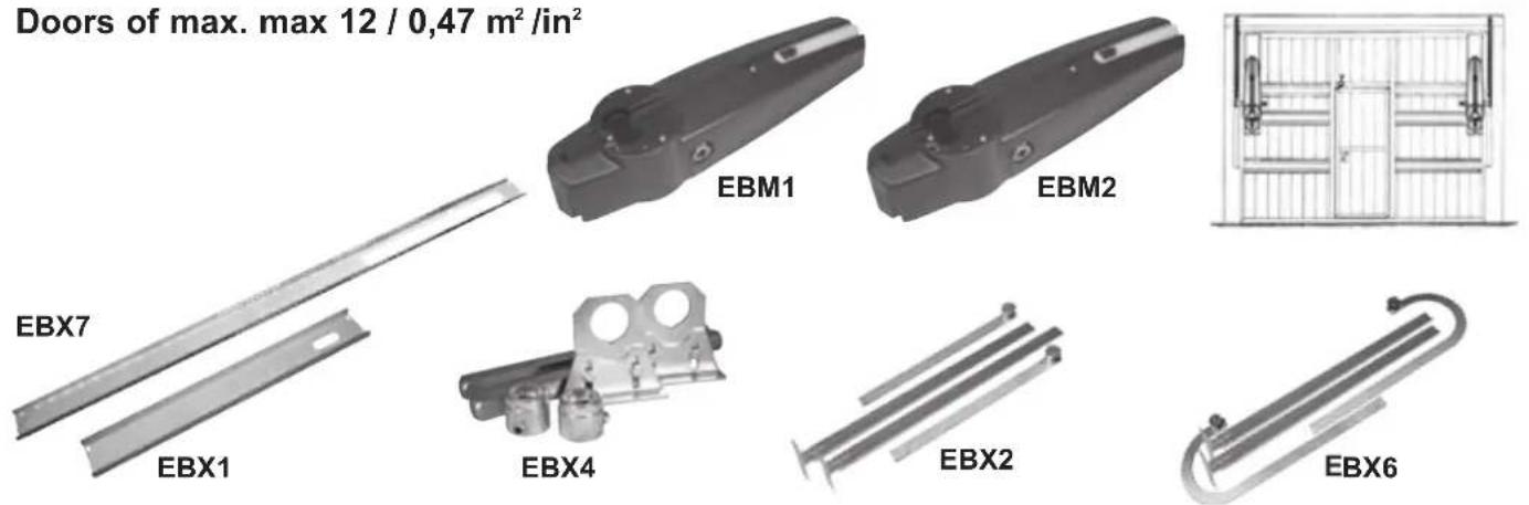
No. 1 - EBM1 - Right-hand side KLYS 9CD MASTER with limit switches, without mounting plate
No. 1 - EBM2 - Right-hand side KLYS 9CD SLAVE without mounting plate
No. 1 - EBX7 - Mounting plate L = 1,95 m for manual up-and-over applications
No. 1 - EBX1 - Mounting plate L = 0,8 m for automated up-and-over applications
No. 1 - EBX4 - Lateral transmission for 2 operators L = 30 cm
No. 1 - EBX2 - Pair of straight levers (or EBX6 - pair of curved levers).
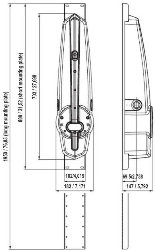
Measurements in mm/in
1
TECHNICAL FEATURES
KLYS 9CD is an irreversible operator employed for counterweight up-and-over garage doors.
The system comprises a reducer unit, lubricated with synthetic grease, a manual release device in the absence of a power supply, and mounting plate (optional) to fasten the operator to the tilting roller device.
IP44 series protection safeguards KLYS 9CD against any sprays of water from any direction.
KLYS 9CD SLAVE, paired with KLYS 9CD MASTER, is equipped with an LED lamp, speed adjustment control and impact sensor in compliance with European legislation currently in force.
| TECHNICAL DATA | KLYS 9CD MASTER + KLYS 9CD SLAVE | |
| Door lever's max. length | cm | 83 |
| Max door surface | m^2 12 (2 motors) | |
| Max door width | m 6 (2 motors) | |
| Max. door height | m | 2,5 |
| Max. torque 1 motor | Nm | 350 |
| Operator RPM | rpm | 1,8 |
| Adjustable opening time | s 15 ÷ 23 | |
| Power supply | 230 V~50 Hz | |
| Motor power supply | 24 Vdc | |
| Power of 1 motor | W | 55 |
| Main line absorption | A 1,2 | |
| Daily cycles suggested | n° | 36 |
| Service | 80 % | |
| Actuator weight | kg | 9,5 MASTER - 8 SLAVE |
| Noise | db | <70 |
| Operating temperature | °C | -10 ÷ +55 °C |
| Protection grade | IP | 44 |
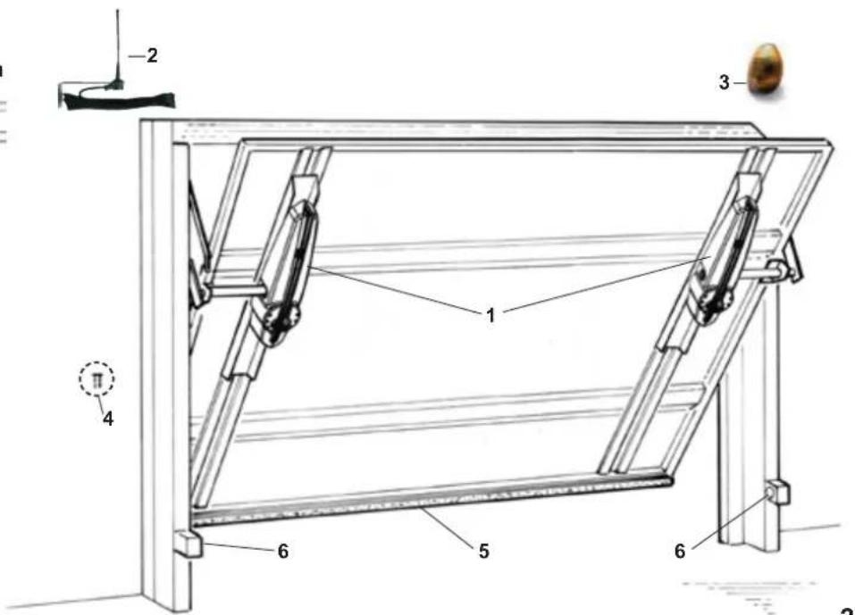
1 - 1 KLYS 9CD MASTER operator
+ 1 KLYS 9CD SLAVE operator
2 - Aerial
3 - Blinker
4 - key selector
5 - Safety edge
6 - Photoelectric cells (internal)
2
PRE-INSTALLATION CHECK
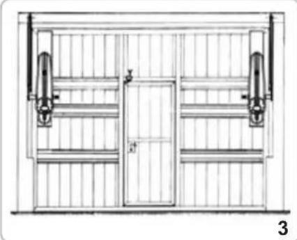
For doors with a total width up to 6 m or a total surface area of 12 square metres, 2 KLYS 9CD (MASTER EBM1 + SLAVE EBM2) device should be used; mounted as shown in Fig. 3, with a PAIR OF STRAIGHT LEVERS code EBX2 (or a PAIR OF CURVED LEVERS code EBX6), the accessories for LATERAL TRANSMISSION for 2 operators cod. EBX4 and 2 SHORT MOUNTING PLATE codes EBX1 or 2 LONG MOUNTING PLATE codes EBX7.
- Check that the available space between the moving frame of the door and external frame with counterweights exceeds 15 mm. If so, the STRAIGHT LEVERS can be mounted. Otherwise, mount the CURVED LEVERS if the distance is less than 15 mm, making sure to remain within the assembly parameters described in Fig. 4.
- Check that the up-and-over door slip bearings are not blocked or obstructed and that the counterweight fastening cables are in correct working order.
- Remove, if present, the manual closing lever connected to the locking device.
N.B. It is obligatory to uniform the characteristics of the door to the standards and laws in force. The door can be automatized only if in a good state and if in accordance with EN 12604 standard.
No trapping points must be generated (for example between horizontally pivoted open door and wall).
natural_image
Technical line drawing of a door frame with vertical supports and a central door (no text or symbols)PARTS TO INSTALL MEETING THE EN 12453 STANDARD
| COMMAND TYPE | USE OF THE SHUTTER | ||
| Skilled persons Skilled (out of a public area*) (public area) | Unrestricted use | ||
| with manned operation | A | B | |
| with visible impulses (e.g. sensor) | or E C or E C and D, or E | ||
| with not visible impulses (e.g. remote control device) | C or E C and D, or E | D, or E | C and D, or E |
| automatic | C and D, or E | C and D, or E | C and D, or E |
* a typical example are those shutters which do not have access to any public way.
A: Command button with manned operation (that is, operating as long as activated),
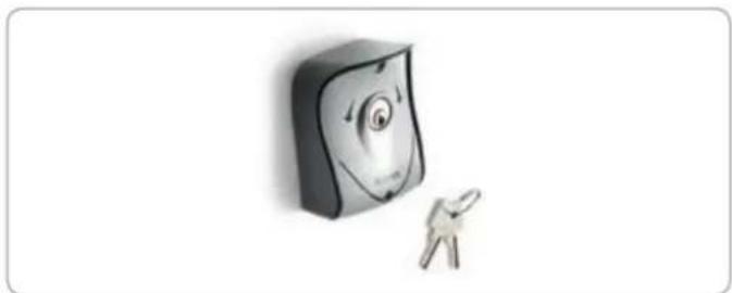
B: Key selector with manned operation, like code EDS1.
C: Adjustable power of the motor.
D: Safety edges and/or other safety devices to keep thrust force within the limits of EN12453 regulation - Appendix A.
E: Photocells, like code EFA1 (To apply every 60÷70 cm for all the height of the column of the gate up to a maximum of 2.5 m - EN 12445 point 7.3.2.1).
INSTALLATION OF 2 MOTOR KLYS 9CD ON DOORS UP TO 12 m²
LEVER APPLICATION
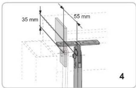
ASSEMBLY OF PAIR OF STRAIGHT LEVERS (code EBX2) BETWEEN MOTOR AND UPPER DOOR FRAME
N.B.: THE PAIR OF STRAIGHT TELESCOPIC LEVERS can be mounted when there is a 15 mm minimum space guaranteed between the moving part of the door and the exterior door frame containing the counterweight.
- Rivets or screws should be used to fix corner parts to the upper frame, in line with measurements shown in Fig. 4: if at the measurement of 35 mm, one finds the reinforcing plate of the door frame, it is possible to fix the brackets directly above this reinforcing plate even if the measurement will not be maintained. In the event that the up-and-over door is already pre-fitted for automated movement, use the attachments provided. Do not use the angles provided.
- Insert the sliding arm sleeve into the angles and secure the pivots and split pins (Fig. 4).
- Make sure that the casing does not touch the up-and-over door movement levers when mounted.
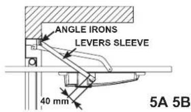
Note: The length of the sleeve and of the sliding arm must be modified in function of overhead door height. Trim the sleeve and the sliding arm so that the sleeve rests 40 mm from the center of the drawbar pivot pin and the sliding arm avoids contact with the rotating dowels located on the angles (Fig. 5A)
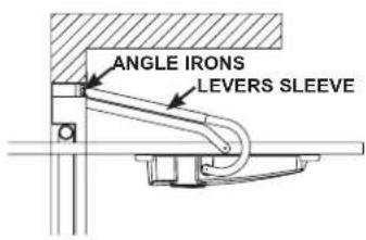
ASSEMBLY OF PAIR OF CURVED LEVERS (code EBX6) BETWEEN MOTOR AND UPPER DOOR FRAME
N.B.: The PAIR OF CURVED TELESCOPIC LEVERS should be mounted when there is less than the 15 mm minimum space guaranteed between the moving part of the door and the exterior door frame containing the counterweight.
- In the event that the up-and-over door is already pre-fitted for automated movement, use the attachments provided. Do not use the angles provided.
- Insert the sliding arm sleeve into the angles and secure the pivots and split pins (Fig. 4).
- Make sure that the casing does not touch the up-and-over door movement levers when mounted.
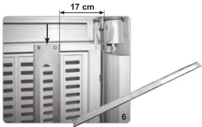
LONG MOUNTING PLATE (FOR NON-AUTOMATED UP-AND-OVER DOORS)
Code EBX7
Position the mounting plate with the upper section (slotted hole to feed electric cable) in top position (Fig. 6).
Fix the mounting spar flush against the upper moving part of the up-and-over door distance of 17 cm from the internal cable of the sheath using 6.3 x 13 self-tapping screws (not included).
SHORT MOUNTING PLATE (FOR AUTOMATED UP-AND-OVER DOORS)
Code EBX1
Calculate the length, L = C - 410 [mm], to which the mounting plate should be vertically fixed (Fig. 7-8).
Position it on the appropriate vertical supports while keeping the upper part (slotted hole to feed electric cable) in a vertical position facing upwards. Fix the mounting plate distance of 17 cm from the internal cable of the sheath using the four feedthrough holes, four 4 metric screws (M6x25) and self-locking nuts (not supplied).
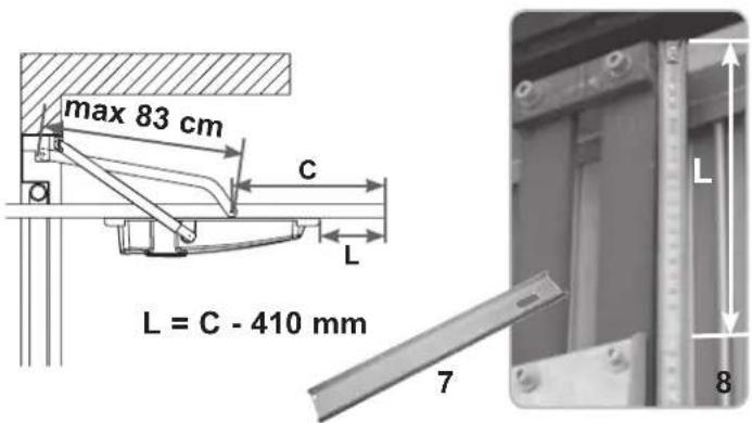
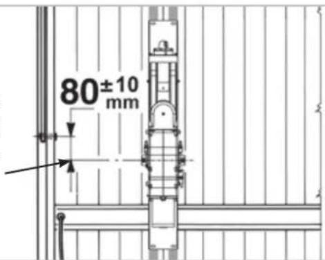
After the assembly's completion, either with the LONG MOUNTING PLATE or with the SHORT MOUNTING PLATE, the reducer's outlet-shaft must be placed in a distance of 80±10 mm from the pivot-axle of the up-and-over door's little arm.
OPERATORS ASSEMBLY
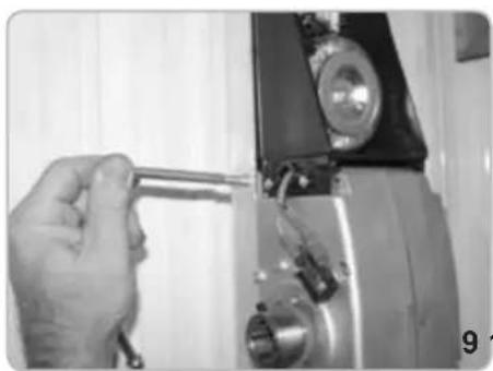
- Fix KLYS 9CD to the mounting plate using the screws supplied (Fig. 9-10-11-12).
- Check the balance of the up-and-over door. If incorrect, and in the event that the doors are not motor-driven, add 9 kg to each counterweight in order to achieve the correct balance.
natural_image
Close-up of a hand holding a tool next to a mechanical component (no visible text or symbols)
natural_image
Close-up of a hand using a wrench to adjust or install a mechanical component (no visible text or symbols)
natural_image
Close-up of a metallic door with a handle and internal compartments (no visible text or symbols)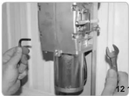
natural_image
Close-up of hands using wrench to adjust a mechanical component (no visible text or symbols)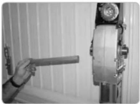
natural_image
Hand holding a cylindrical object next to a vertical metallic device mounted on a wall (no visible text or symbols)RE-BALANCING OF THE DOOR
When installing 2 KLYS 9CD operator on a door, 9 kg extra each side must be applied on the existing counterweights.
POSITIONING OF THE SQUARE DRIVING SHAFT ON THE OPERATORS
- Insert the square driving shaft into the operator take-off shaft end (Fig. 13).
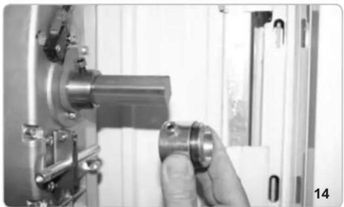
CORNER TRACK BLOCK FIXING - 2 MOTORS (Code EBX4)
- Insert the bushing with locking pins for both sides of the square driving shaft 20 x 20 (Fig. 14).
- Fix the adjustable support angle bars to the moveable up-and-over door frame in line with the square driving shaft (Fig. 15). WARNING: fastening screws not supplied.
- Insert bushings in the supports (Fig. 16), bolt the support structures into place (Fig. 17).
- Check that the STRAIGHT LEVERS (code EBX2) are perfectly perpendicular and do not touch the counterweight casing or moving door parts. The PAIR OF CURVED LEVERS (code EBX6) should be mounted when there is less than the 15 mm minimum space guaranteed between the moving part of the door and the exterior door frame containing the counterweight (while aligned with measurements described in Fig. 4).
natural_image
Close-up of a hand adjusting a metallic mechanical component with a cylindrical part inserted, no visible text or symbols.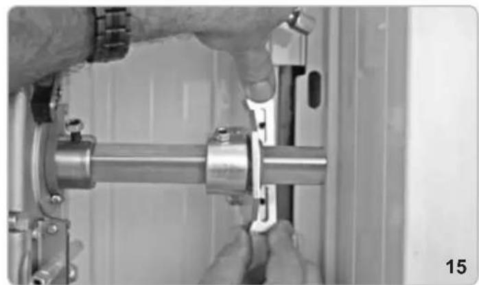
natural_image
Close-up of hands assembling a metallic mechanical component (no visible text or symbols)
natural_image
Close-up of a hand operating a mechanical assembly with a metallic pipe and clamped components (no visible text or symbols)
natural_image
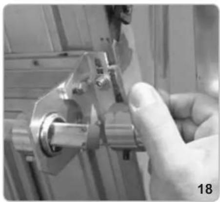
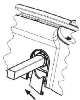
Close-up of a mechanical assembly with a metallic rod and bolted joint (no visible text or symbols)CORNER TRACK BLOCK TUBING AND LEVER FIXING
- Insert the lever into the sleeve and the welded bushing into the square driving shaft (Fig. 18).
- Begin to lock the pins positioned on the track shaft into position (Fig. 19-20) on the centring bush and relative lock nuts (Fig. 21).
- Fix the lever to the tubing tight with locking pin and lock nut (Fig. 22-23).
- With the help of the handles inserted in the relative realease mechanism, mechanically release the operators (Fig. 24-25)
- Verify the correct movement of the door and then lock the motors again.
- Lubricate the door's levers and guides.
natural_image
Close-up of a hand using a tool to adjust or install a mechanical component (no visible text or symbols)
natural_image
Close-up of a hand adjusting a mechanical component with a metallic shaft and pipe (no visible text or symbols)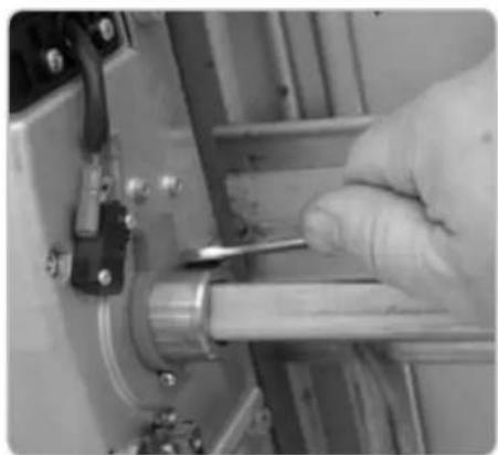
natural_image
Close-up of a gloved hand using a tool to adjust or install a mechanical component (no visible text or symbols)
natural_image
Close-up of a hand holding a metallic mechanical component, no visible text or symbols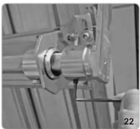
natural_image
Close-up of a mechanical assembly with metallic components and a numbered label '22' (no readable text or symbols)
natural_image
Close-up of a hand using a tool to adjust or install a mechanical component (no visible text or symbols)
natural_image
Close-up of a hand operating a mechanical tool with a metallic component (no visible text or symbols)
natural_image
Close-up of industrial machinery components including a metallic frame and mechanical bracket (no visible text or symbols)ELECTRICAL CONNECTION
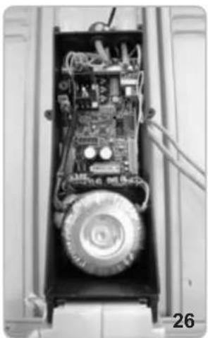
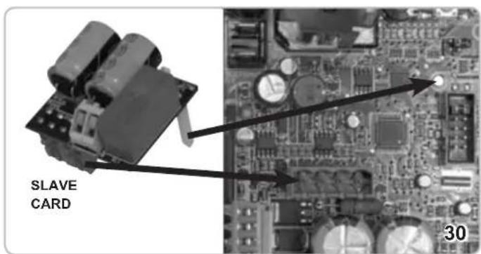
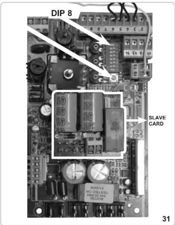
Once you have removed the covers of the control panel boxes both on the Master and on the Slave motors (pict 26), insert the SLAVE control panel onto the MASTER control panel inside the MASTER operator (Fig. 30 - 31) inserting the spacer support in the appropriate hole (Fig. 30). Carry out the electrical connection as shown in Fig. 69 in order to check 'dead man's switch' control to up-and-over door commands.
WARNING: IPX4 can only be guaranteed by mounting the rubber cable fairleads in the electrical switchboard into the relative container holes (Fig. 27) and the rounded slotted wire seal on the cover latch (Fig. 28).
natural_image
Interior view of an electronic device showing internal components and wiring (no visible text or symbols)
natural_image
Technical line drawing of a mechanical housing assembly with wheels and internal components (no text or symbols)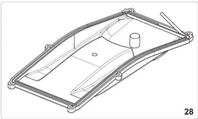
natural_image
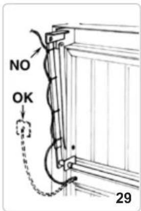
Technical line drawing of a mechanical component with no visible text or symbolsThe electrical cable that powers the operator should be fixed to the telescopic lever using the plastic bands shown in Fig. 29.
The cable should be curved in order that it is not subject to twist, tension or tearing while the door is in movement. Cables exiting the door plate hole should be protected with some form of sheath to avoid their being cut during movement.
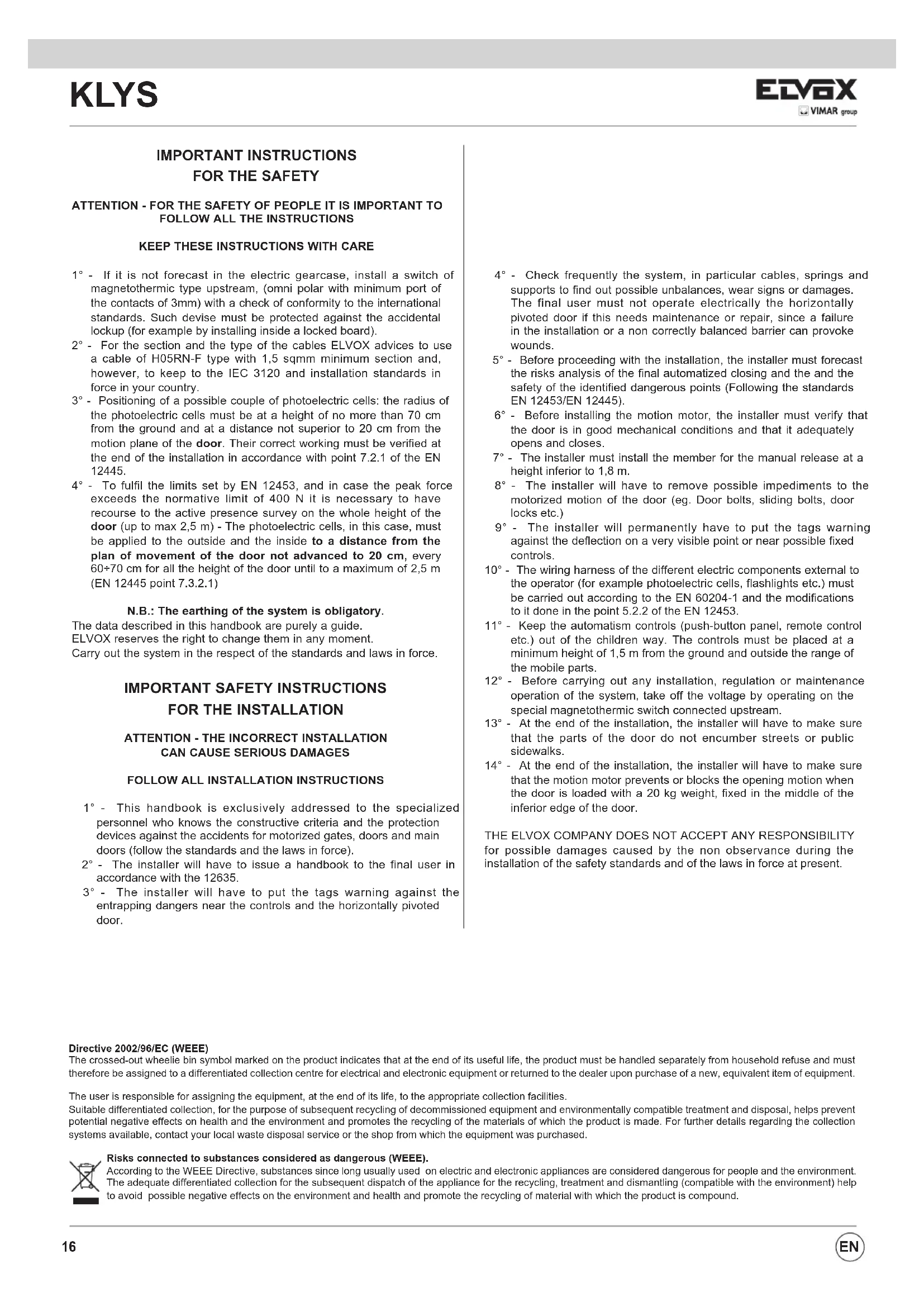
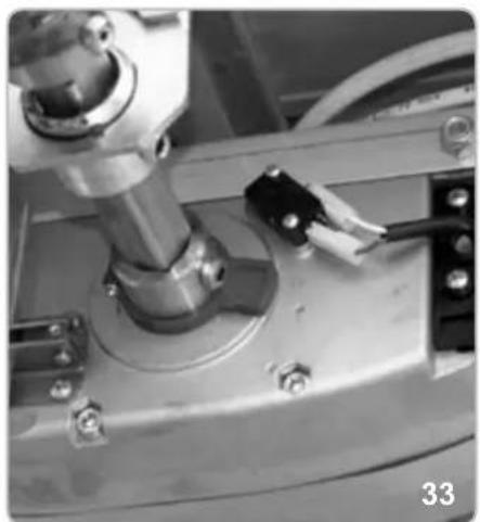
LIMIT SWITCHES ADJUSTMENT - MASTER OPERATOR
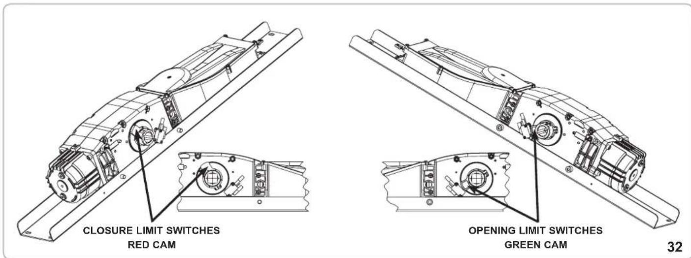
- Position DIP 8 to ON and press the command button on the electrical switchboard (Fig. 31) to start up-and-over door movement. Release the button once the operation has been carried out. Slacken the holding screw for the green cam and turn until activating the microswitch (Fig. 34).
- Tighten the green cam holding screw (Fig. 35).
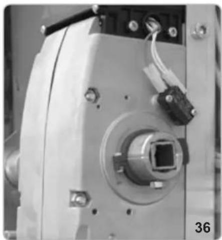
- Press the key on the electronic switchboard (Fig. 31) to close the up-and-over door movement. Release the button once the closing operation has been completed. Slacken the holding screw for the red cam and turn until the microswitch is activated (Fig. 37).
- Tighten the red cam holding screw (Fig. 38).
- Carry out a complete opening and closing cycle to check that the cams are positioned perfectly. Correct positions if required.
- Turn DIP8 to OFF.
Refer to the section ELECTRICAL CONNECTIONS for connection to auxiliary units and switchboard functions.
Close the electrical box with the appropriate cover using the 6 screws provided.
OPENING LIMIT SWITCHES ADJUSTMENT
natural_image
Close-up of a mechanical assembly with a metallic component and bolts (no visible text or symbols)
natural_image
Close-up of hands using a tool to adjust or install a mechanical component (no visible text or symbols)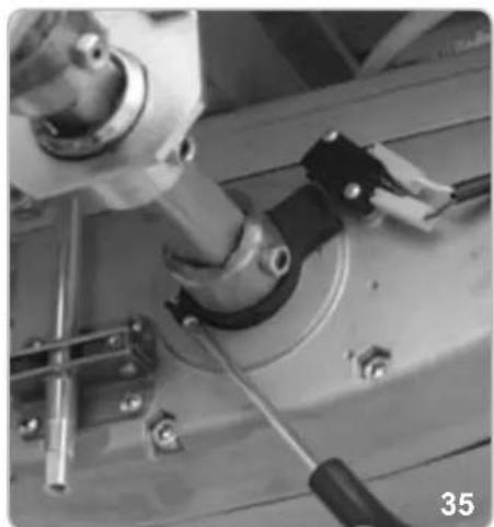
natural_image
Close-up of mechanical components including a cylindrical component and a black tool, no visible text or symbolsCLOSURE LIMIT SWITCHES ADJUSTMENT
natural_image
Close-up of a mechanical device with a central square component and wiring (no visible text or symbols)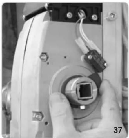
natural_image
Close-up of a hand holding a camera lens component, no visible text or symbols
natural_image
Close-up of a hand holding a tool interacting with an electronic device component (no visible text or symbols)CASING MOUNTING
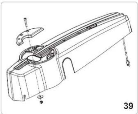
- Mount the fixed handle (without release warning) on the casing using the screws, bolt and washer supplied, inserting them on the opposite side to the release device (Fig. 39).
- Apply the cap on the side of the operator where the driving shaft if not sticking out (pitc 46).
- Connect the illuminator unit connector to the cable leading from the electrical switchboard (Fig. 40 and 41).
- Insert the casing on the reducer, making sure to position it on the mounting plate in the appropriate position and centre the release spar with the predrilled holes on the casing. Fasten the casing to the motor with the screws supplied (Fig. 43 and 44) and then fix the release device handle (Fig. 45) to the motor release device spar.
- Apply the lateral cap.
The operator is now installed and ready to carry out tutoring programme operations (refer to PROGRAMMING section).
natural_image
Technical line drawing of a mechanical component with no visible text or symbols
natural_image
Close-up of hands installing or adjusting a black electrical component with visible traces (no text or symbols)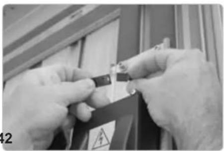
natural_image
Close-up of hands holding a small electronic component with warning symbol (no readable text or symbols)
natural_image
Close-up of a black electrical component with warning symbol and safety tag, mounted on a metal frame (no readable text or symbols)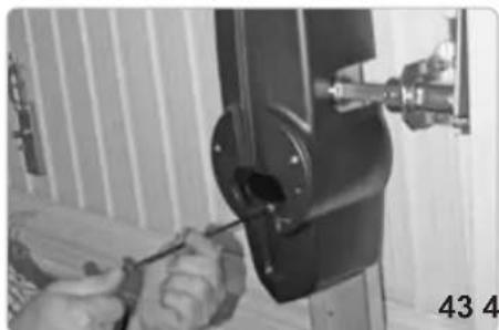
natural_image
Close-up of hands using a screwdriver to adjust or install a mechanical component (no visible text or symbols)
natural_image
Close-up of hands using a tool to adjust or install a mechanical component (no visible text or symbols)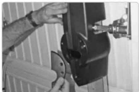
natural_image
Person operating a mechanical device with a tool, no visible text or symbols
natural_image
Four technical illustrations of a mechanical component with internal channels and arrows indicating movement (no text or symbols)
natural_image
Four technical illustrations of a mechanical piston-cranked pump mechanism, showing internal components and motion direction (no text or symbols)INTERNAL RELEASE DEVICE HANDLE
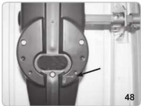
KLYS 9CD is generally supplied with a manual release device handle that can be operated from inside the premises (Fig. 48).
In the event of power failure turn both the handles of the operators.
If the release mechanism is positioned to the right turn the right-hand-side handle anticlockwise (with operators with release on the left hand side, turn the handle clock wise). This will unlock the reducer and allow the door to be opened manually.
Turn the handle back to its original position in order to block the reducer.
In order to carry out the manual movement of the spar safely, it is important to check that:
- The door is supplied with suitable handles.
- Handles are positioned in such a way so as not to create hazard points during their use.
- The manual effort required to move the door should not exceed 225 N for doors installed for private use and 390 N for doors for commercial or industrial use (parameters set by item 5.3.5 of EN 12453 standard).
WARNING: The release mechanism may cause the door to move in an unpredictable fashion if the door has not been correctly centred and balanced. In such cases, it is necessary to carry out the necessary balancing operations to the up-and-over doors.
natural_image
Close-up of a mechanical joint or bracket component with a labeled arrow pointing to a feature (no text or symbols visible)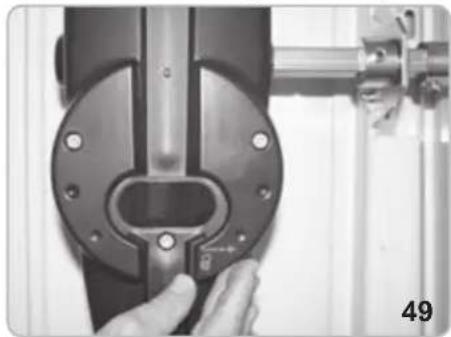
natural_image
Close-up of a hand adjusting a mechanical component with a metallic bracket and mounting bracket (no visible text or symbols)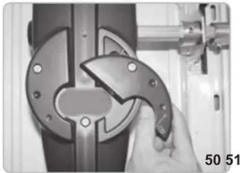
natural_image
Close-up of a hand using a tool to adjust or install a mechanical component, no visible text or symbols.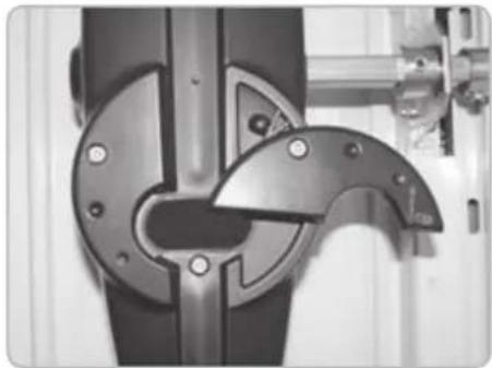
natural_image
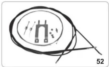
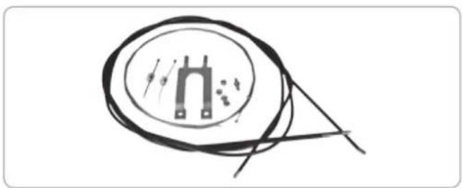
Close-up of a mechanical component with metallic parts and mounting holes (no visible text or symbols)CABLE UNLOCKING RELEASE
With such type of release system, in case of black outs, it is possible to release the motors from the outside. It is therefore advisable, when the garage door is the only possible way of access.
The cable unlocking release can be installed either to the left or right of the operator depending on the position of the locking handle of the garage door.
The release device (code EBS2) is mounted on the existing locking apparatus installed on the up-and-over door. ATTENTION: in case of 2 locks on the door, fit for each lock unlocking release EBS1.
For the assembly see the accessory specific instructions.
Follow the instructions described from Fig. 53 to 120.
natural_image
Pure electrical circuit lines without any symbols
natural_image
Close-up of a mechanical assembly with a hand holding a tool, no visible text or symbols
natural_image
Close-up of mechanical components with bolts and a tool, no visible text or symbols
natural_image
Close-up of a hand holding a tool near a curved wire on a tiled surface (no text or symbols visible)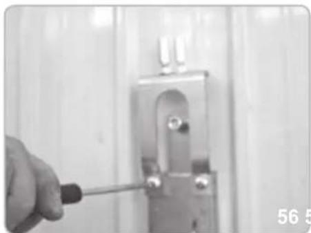
natural_image
Close-up of a hand using a screwdriver to adjust or install a metal bracket (no text or symbols visible)
natural_image
Close-up of a medical or laboratory tool with a metallic rod extending upward (no visible text or symbols)
natural_image
Close-up of a hand using a screwdriver to adjust a small component on a wall (no visible text or symbols)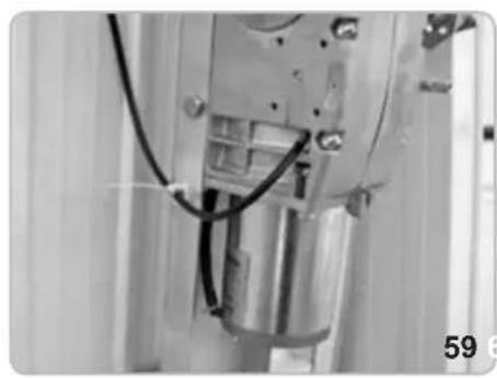
natural_image
Close-up of a mechanical assembly with visible wiring and components (no text or symbols)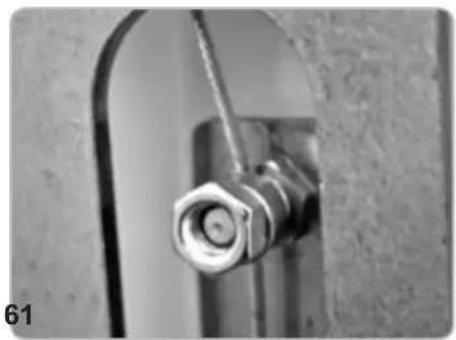
natural_image
Close-up of a metallic pipe fitting with a hexagonal bolt inserted, mounted on a curved metal bracket (no text or symbols visible)
natural_image
Close-up of a hand using a tool to test or inspect a mechanical component (no visible text or symbols)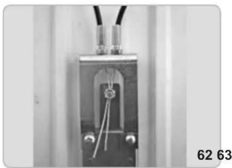
natural_image
Close-up of a mechanical or electrical component with wires and connectors, no visible text or symbols
natural_image
Close-up of a metallic electrical connector with wires and a metal rod (no visible text or symbols)
natural_image
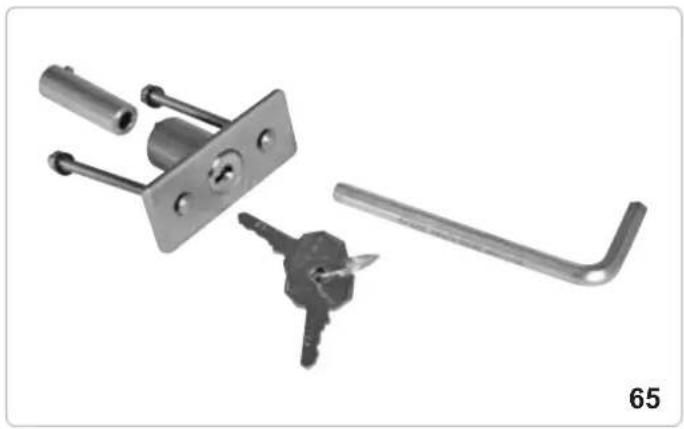
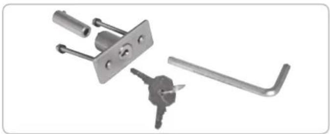
Exterior view of a white modular storage panel with two black sensors and wiring, no visible text or symbolsALLEN KEY LOCK UNLOCKING RELEASE
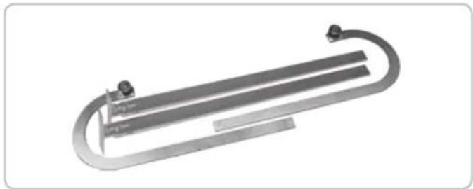
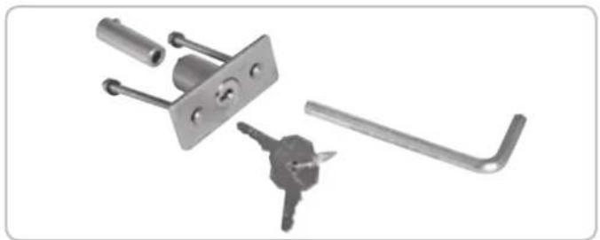
It is also possible to release the locking device from the outside using auxiliary device code EBS3 and customised key.
For the assembly see the accessory specific instructions.
Follow the simple operations described below in order to carry out unlocking operations:
- Remove the lock barrel with the appropriate key (Pic. 66).
- Insert an allen wrench (no. 6) in the hole of the plate as far as the release device bushing (Pic. 67).
- Turn the hexagonal key in the direction indicated on the sticker on the up-and-over door until the operator unlocking device is activated (Pic. 68).
- In order to lock the reducer, turn the hexagonal key in the direction indicated on the sticker on the up-and-over door (Pic. 68).
natural_image
Mechanical lock assembly with key and handle components (no text or symbols visible)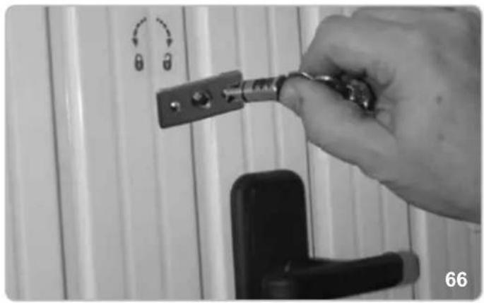
natural_image
Hand holding a key inserted into a door lock, with no visible text or symbols on the main subject.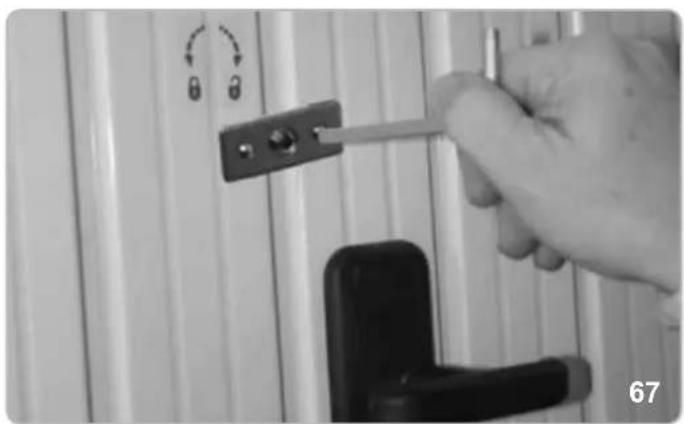
natural_image
Hand holding a tool interacting with a door handle and lock, no visible text or symbols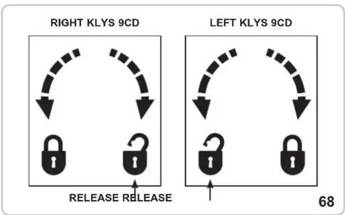
ATTENTION!
The coupling of the releases with closed door doesn't guarantee the total closing of the door. It will partially remain opened until an electrical movement. The corrected closing will only happen with electrical closing completed.
MAINTENANCE
To be undertaken only by specialized staff after disconnecting power supply.
Grease the fulcrums, the counterweight channels, the telescopic levers and carry out the necessary impacts force check as for EN12345 and EN12445 once a year.
ELECTRIC CONNECTIONS
SICUT MASTER
WIRING CONNECTIONS BETWEEN MASTER AND SLAVE MOTORS
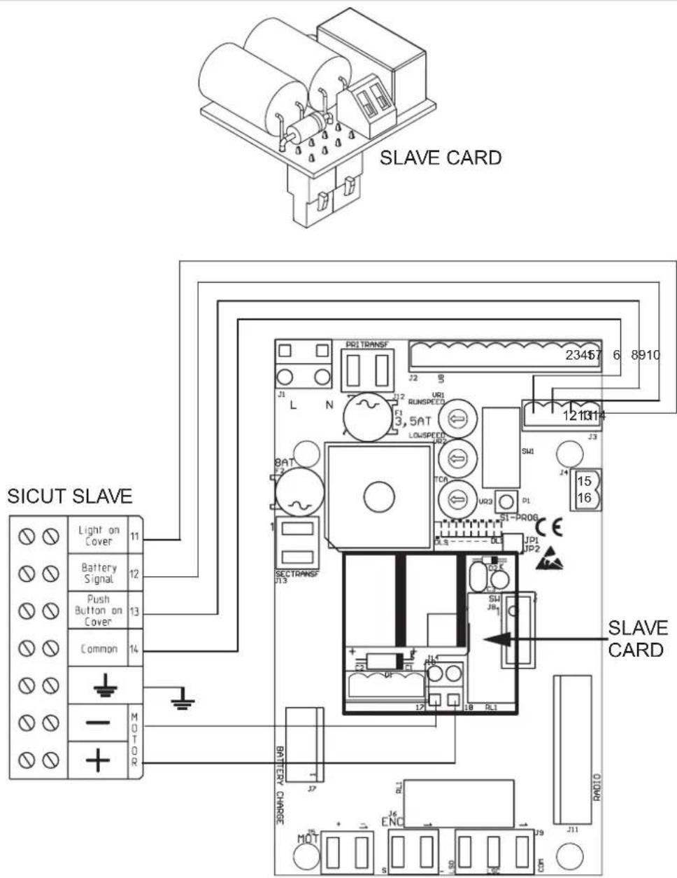
SLAVE card allows users to operate a second motor on up-and-over doors with a surface area exceeding 9 square metres.
Switch off the power supply to the system and insert the slave board into the J10 connector.
The board will be automatically configured once the system is switched back on preset for 2 motors.
Connect the 4 wires (min. diam. 0,5 mm ^2 ) from the contacts 11-12-13-14 of the Master control panel to the contacts 11-12-13-14 on the SLAVE control panel.
Connect the motor wires (min. diam. 1,5 mm ^2 ) from the contacts 17-18 of the SLAVE control panel to the contacts - and + available in the box on the motor slave.
PEDESTRIAN SECURITY (terminals 5 ad 6)
In the event that the main up-and over-doors are also equipped with pedestrian access, connect a microswitch (N.C. closed pedestrian access door) to signal to the control panel that the pedestrian door is open or closed.
Connection should be carried out using terminals 5 and 6 (where no safety strips are connected), or, where present, in safety strip contact series.
To ensure correct system operations, the DL3 LED lamp should be illuminated, signalling that the pedestrian door is closed correctly.
If the led DL3 is OFF, the movement of the garage door will not be possible, because the pedestrian door is open.
NOTE: Create a jumper if terminals 5 and 6 are not used by safety strips or other devices.
OPTIONALS - For the connections and the technical data of the fixtures follow the relevant handbooks.
CABLE UNLOCKING RELEASE
natural_image
Simple line drawing of a circular object with a U-shaped symbol inside, connected to a rod (no text or labels)code EBS1
CURVED LEVERS
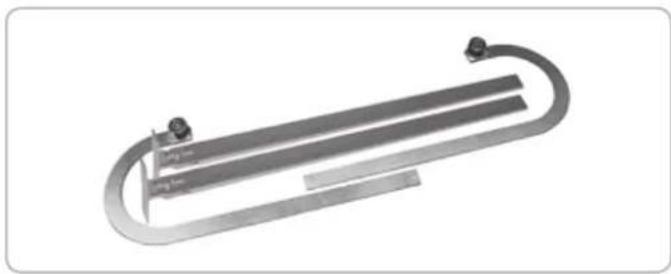
natural_image
3D rendering of a U-shaped metal object with two vertical supports and a central horizontal bar (no text or symbols visible)code EBX6
ALLEN KEY LOCK UNLOCKING RELEASE
natural_image
Collection of metal hardware components including lock, handle, key, and lever (no text or symbols visible)code EBS3
BLINKER

natural_image
Close-up of a translucent, segmented object with internal striations, possibly a seed or crystal (no text or symbols visible)code ELA1/L
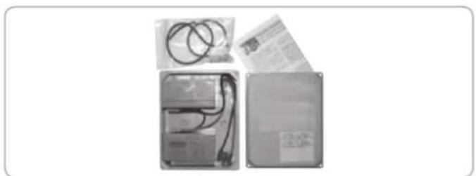
BOX WITH BATTERIES
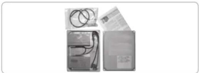
natural_image
Three electronic devices with visible wiring and connectors, no text or symbols presentcode EBB1
PHOTOCELLS

natural_image
Two black rectangular electronic devices with reflective surfaces, no visible text or symbolscode EFA1
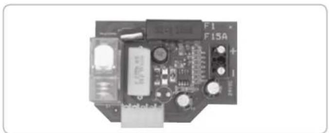
BATTERY CHARGE CARD KLYS 9CD 24 V
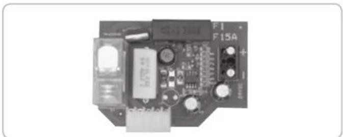
natural_image
Electronic circuit board with components and connectors (no readable text or symbols)code ECB3
KEY SELECTOR FOR WALL-INSTALLATION
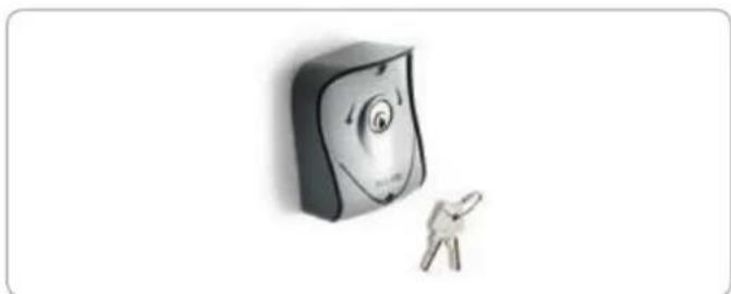
natural_image
Illustration of a smiling computer monitor with a small figure pointing at it (no text or symbols)code EDS1
RADIO TRANSMITTER
natural_image
White electronic device labeled 'EDGX' with two circular buttons and a cord, shown against a plain white background (no text beyond brand name)code ETR5
EC DECLARATION OF CONFORMITY
(Declaration of incorporation of partly completed machinery annex IIB Directive 2006/42/EC)
No.: ZDT00446.00
The undersigned, representing the following manufacturer
Elvox SpA
Via Pontarola, 14/a
35011 Campodarsego (PD) Italy
herewith declares that the products
ACTUATORS FOR GARAGE DOORS - SERIES KLYS
Articles
KLYS 9CD
are in conformity with the provisions of the following EC directive(s) (including all applicable amendments) and that the following standards and/or technical specifications have been applied:
LV Directive 2006/95/EC: EN 60335-2-95 (2004)
EMC Directive 2004/108/EC: EN 61000-6-1 (2007), EN 61000-6-3 (2007) + A1 (2011),
EN 61000-6-2 (2005), EN 61000-6-4 (2007) + A1 (2011)
R&TTE Directive 1999/5/EC: EN 301 489-3 (2002), EN 300 220-3 (2000)
Machinery Directive 2006/42/EC EN 13241 (2003) + A1 (2011), EN 12453 (2000)
Further hereby declares that the product must not be put into service until the final machinery into which it is to be incorporated has been declared in conformity with the provisions of Directive 2006/42/EC, where appropriate.
Declares that the relevant technical documentation has been compiled by Elvox SpA in accordance with part B of Annex VII of Directive 2006/42/EC and that the following essential requirements of this Directive have been applied and fulfilled: 1.1.1, 1.1.2, 1.1.3, 1.1.5, 1.1.6, 1.2.1, 1.2.2, 1.2.6, 1.3.1, 1.3.2, 1.3.3, 1.3.4, 1.3.7, 1.3.8, 1.3.9, 1.4.1, 1.4.2, 1.5.1, 1.5.2, 1.5.4, 1.5.5, 1.5.6, 1.5.7, 1.5.8, 1.5.9, 1.6.1., 1.6.2, 1.7.1, 1.7.2, 1.7.3, 1.7.4, 4.1.2.
I undertake to make available, in response to a reasoned request by the national authorities, any further supporting product documents they require.
Campodarsego, 06/05/2013
The Managing Director
Note: The contents of this declaration correspond to what declared in the last revision of the official declaration available before printing this manual. The text herein has been re-edited for editorial purposes. A copy of the original declaration can be requested to Elvox SpA
INSTRUCTIONS IMPORTANTES POUR LA SECURITE
ATTENTION - POUR LA SECURITE DES PERSONNES, IL EST IMPORTANT DE SUIVRE TOUTES LES INSTRUCTIONS
CONSERVER SOIGNEUSEMENT CES INSTRUCTIONS
Directive 2002/96/CE (WEEE, RAEE)
Mesures en mm
1
CARACTÉRISTIQUES TECHNIQUES
natural_image
Technical line drawing of a door frame with vertical supports and a central door (no text or symbols)PARTIES À INSTALLER CONFORMÉMENT À LA NORME EN12453
natural_image
Close-up of a hand holding a tool next to a mechanical component (no visible text or symbols)
natural_image
Close-up of a hand using a wrench to adjust or install a mechanical component (no visible text or symbols)
natural_image
Close-up of a metallic door with a handle and internal compartments (no visible text or symbols)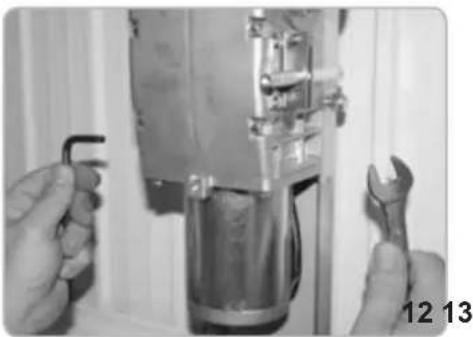
natural_image
Close-up of hands adjusting a mechanical component with wrench, no visible text or symbols
natural_image
Hand holding a tool next to a vertical mechanical device (no visible text or symbols)ÉQUILIBRER A NOUVEAU LA BASCULANTE
natural_image
Close-up of a hand adjusting a metallic mechanical component with a cylindrical part inserted, no visible text or symbols.
natural_image
Close-up of hands assembling a metallic mechanical component (no visible text or symbols)
natural_image
Close-up of a mechanical assembly with a metallic pipe and clamped components (no visible text or symbols)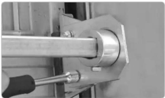
natural_image
Close-up of a metallic mechanical assembly with a tool inserted, no visible text or symbolsFIXATION DU TUBE ET DES LEVIERS DE RENVOI LATÉRAL
natural_image
Close-up of a hand using a tool to adjust or install a mechanical component (no visible text or symbols)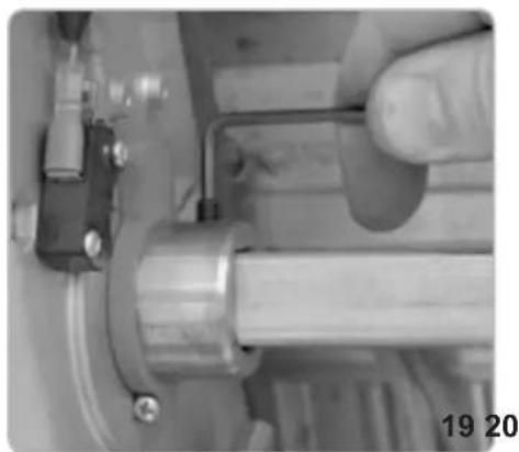
natural_image
Close-up of a hand adjusting a mechanical component with a metallic shaft and pipe (no visible text or symbols)
natural_image
Close-up of a gloved hand using a tool to adjust or install a mechanical component (no visible text or symbols)
natural_image
Close-up of a hand holding a metallic mechanical component, no visible text or symbols
natural_image
Close-up of a mechanical assembly with metallic components and a numbered label '22' (no readable text or symbols)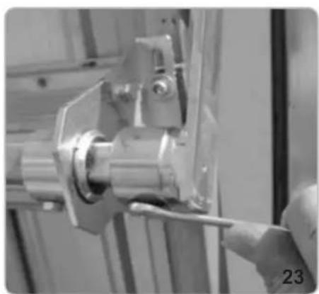
natural_image
Close-up of a hand using a tool to adjust or install a mechanical component (no visible text or symbols)
natural_image
Close-up of a hand operating a mechanical tool with a metallic component (no visible text or symbols)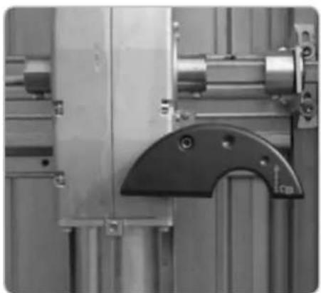
natural_image
Close-up of industrial machinery components including a metallic frame and mechanical bracket (no visible text or symbols)RACCORDEMENT ÉLECTRIQUE
natural_image
Interior view of an electronic device showing internal components and wiring (no visible text or symbols)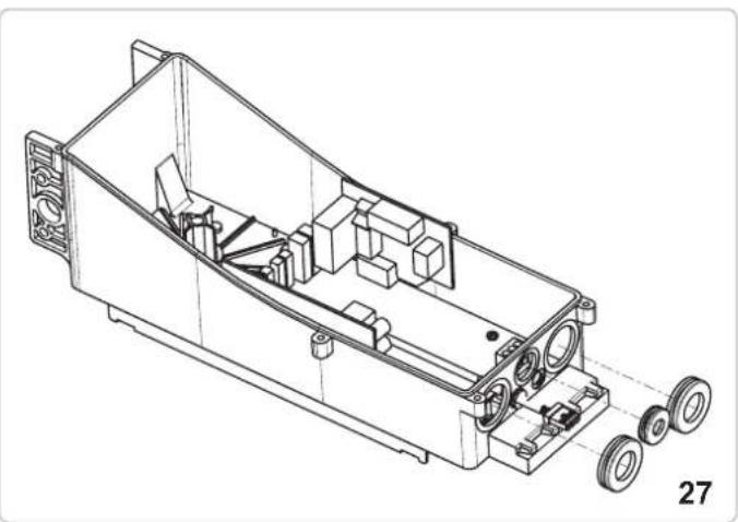
natural_image
Technical line drawing of an internal mechanical housing with wheels and components (no text or symbols)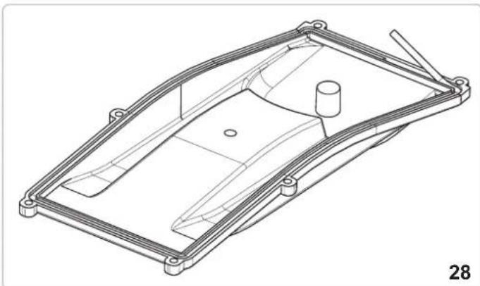
natural_image
Technical line drawing of a mechanical housing or enclosure component (no text or symbols)FIXATION DU CÂBLE ÉLECTRIQUE COTE OPERATEUR MASTER
natural_image
Close-up of a mechanical assembly with a metallic component and bolts (no visible text or symbols)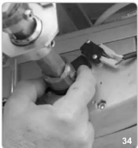
natural_image
Close-up of hands using a tool to adjust or install a mechanical component (no visible text or symbols)
natural_image
Close-up of mechanical components with no visible text or symbolsRÉGLAGE DU FIN DE COURSE FERMETURE

natural_image
Close-up of a mechanical device with a central square component and wiring (no visible text or symbols)
natural_image
Close-up of a hand holding a camera lens component, no visible text or symbols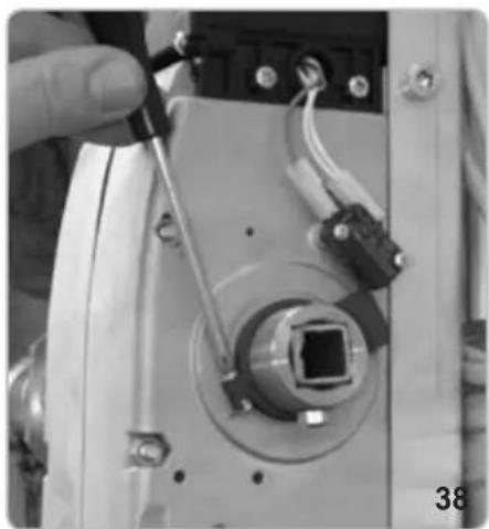
natural_image
Close-up of a hand holding a tool next to a mechanical component with wires and connectors (no visible text or symbols)FIXATION DU CARTER
natural_image
Technical line drawing of a mechanical component with no visible text or symbols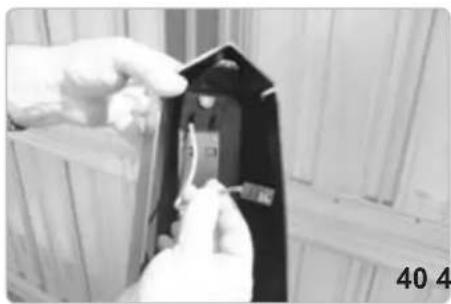
natural_image
Close-up of hands installing or adjusting a black electrical component with visible traces (no text or symbols)
natural_image
Close-up of hands holding a small electronic component with warning symbol (no readable text or symbols)
natural_image
Close-up of a black electrical component with warning symbol and safety tag, mounted on a metal frame (no readable text or symbols)
natural_image
Close-up of hands using a screwdriver to adjust or install a mechanical component (no visible text or symbols)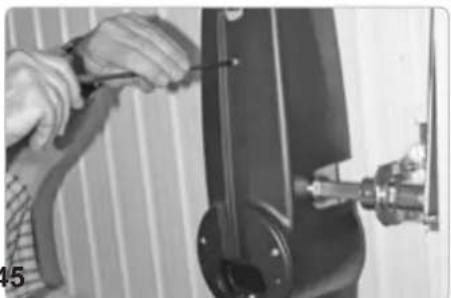
natural_image
Close-up of hands using a tool to adjust or install a mechanical component (no visible text or symbols)
natural_image
Person operating a mechanical device with a tool, no visible text or symbols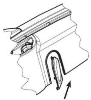
natural_image
Technical line drawing of a mechanical component with an arrow indicating direction (no text or symbols)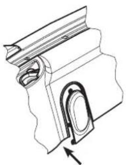
natural_image
Technical line drawing of a mechanical component with an arrow indicating direction (no text or symbols)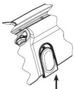
natural_image
Technical line drawing of a mechanical component with an arrow indicating direction (no text or symbols)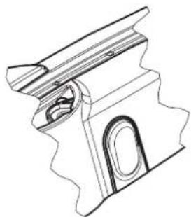
natural_image
Technical line drawing of a mechanical component with no visible text or symbols46
natural_image
Technical line drawing of a mechanical assembly with a lever and base mount (no text or symbols)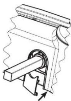
natural_image
Mechanical assembly diagram showing a gear and shaft mechanism (no text or labels)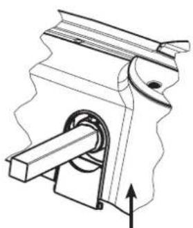
natural_image
Mechanical assembly diagram showing a piston and lever mechanism (no text or labels)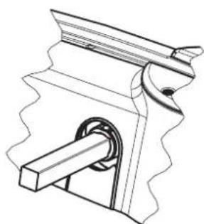
natural_image
Technical line drawing of a mechanical clamp or bracket assembly (no text or symbols)47
DÉBLOCAGE INTERNE À POIGNÉE
natural_image
Close-up of a mechanical joint or bracket component with a labeled arrow pointing to a feature (no text or symbols visible)
natural_image
Close-up of a hand adjusting a mechanical component with a circular housing and metal bracket (no visible text or symbols)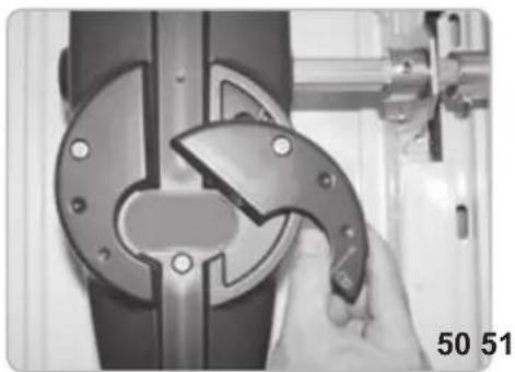
natural_image
Close-up of a hand using a tool to cut or adjust a mechanical component, no visible text or symbols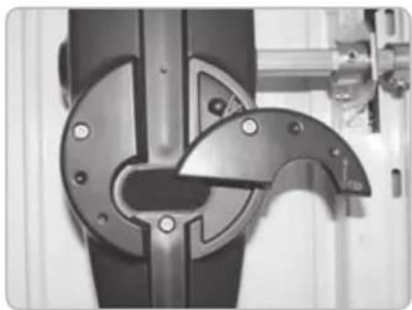
natural_image
Close-up of a mechanical component with metallic parts and mounting holes (no visible text or symbols)DEBLOCAGE A FIL
natural_image
Pure electrical circuit lines without any symbols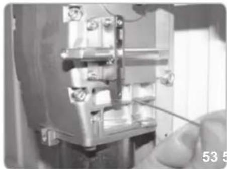
natural_image
Close-up of a mechanical assembly with a hand holding a tool, no visible text or symbols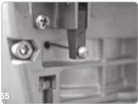
natural_image
Close-up of mechanical components with bolts and a tool, no visible text or symbols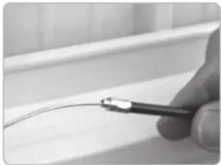
natural_image
Close-up of a hand holding a tool near a curved wire on a tiled surface (no text or symbols visible)
natural_image
Close-up of a hand using a screwdriver to adjust or install a metal bracket (no text or symbols visible)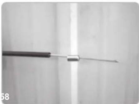
natural_image
Close-up of a medical or laboratory tool with a metallic rod extending upward (no visible text or symbols)
natural_image
Close-up of a hand using a screwdriver to adjust a small component on a wall (no text or symbols visible)
natural_image
Close-up of a mechanical assembly with visible wiring and components (no text or symbols)
natural_image
Close-up of a metallic pipe fitting with a hexagonal bolt inserted, mounted on a curved metal bracket (no text or symbols visible)
natural_image
Close-up of a hand using a tool to test or inspect a mechanical component (no visible text or symbols)
natural_image
Close-up of a mechanical or electrical component with wires and connectors, no visible text or symbols
natural_image
Close-up of a metallic electrical component with wires and a metal rod inserted (no visible text or symbols)
natural_image
Exterior view of a white modular storage panel with two black connectors and wiring, no visible text or symbolsDEBLOCAGE CLE D'ALLEN AVEC SERRURE
natural_image
Mechanical components including a lock, handle, key, and wrench (no text or symbols visible)
natural_image
Hand holding a key inserted into a door lock, with no visible text or symbols
natural_image
Close-up of a hand holding a tool with a lock, against a white wall panel (no text or symbols visible)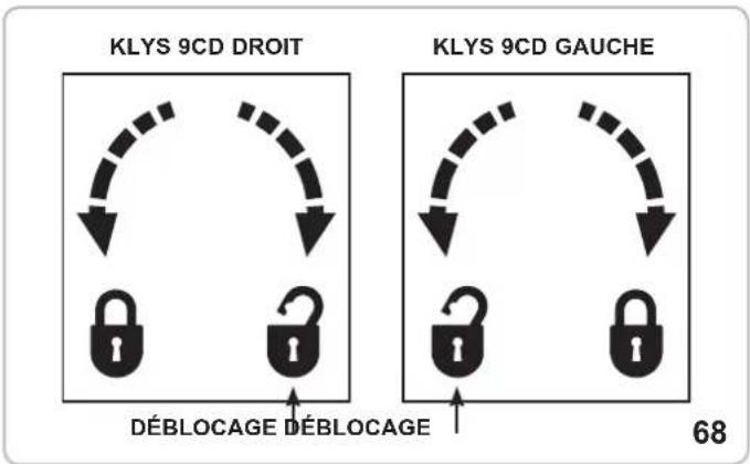
flowchart
graph TD
    A["KLYS 9CD DROIT"] --> B["Deblocage"]
    C["KLYS 9CD GAUCHE"] --> D["Deblocage"]
    B --> E["Lock"]
    D --> F["Lock"]
    style A fill:#f9f,stroke:#333
    style C fill:#f9f,stroke:#333
    style B fill:#ccf,stroke:#333
    style D fill:#ccf,stroke:#333
ATTENTION!
SÉCURITÉ POUR PORTE PIÉTONNIÈRE - PEDESTRIAN SECURITY (bornes 5-6)
natural_image
Simple line drawing of a cable with a U-shaped magnet inside, no text or symbols presentcode EBS1
natural_image
Mechanical component with curved metallic frame and mounting base (no visible text or symbols)code EBX6
DEBLOCAGE CLE D'ALLEN AVEC SERRURE
natural_image
Collection of metal hardware components including lock, handle, and key (no text or symbols visible)code EBS3
FEU CLIGNOTANT

natural_image
Close-up of a translucent, oval-shaped object with internal striations, possibly a shell or crystal (no text or symbols visible)code ELA1/L
CONTAINEUR AVEC BATTERIES
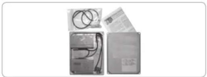
natural_image
Three electronic components: a battery pack, a wire harness, and a rectangular case with cable (no visible text or symbols)code EBB1
PHOTOCELLULES

natural_image
Two black rectangular electronic devices with rounded tops, shown against a white background (no text or symbols visible)code EFA1
FICHE DE CHARGE BATTERIE KLYS 9CD 24 V
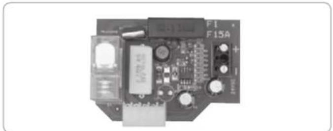
natural_image
Electronic circuit board with components and connectors (no readable text or symbols)code ECB3
natural_image
Illustration of a smiling computer monitor with a small figure pointing at it (no text or symbols)code EDS1
EMETTEUR RADIO
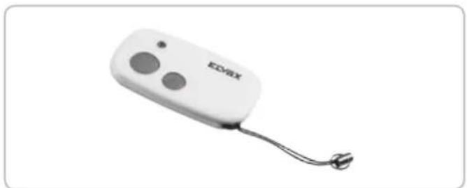
natural_image
White electronic device labeled 'EDVAX' with two circular buttons and a cord, shown against a plain white background (no additional text or symbols visible)code ETR5
DÉCLARATION DE CONFORMITÉ
- FISSAGGIO CAVO ELETTRICO LATO OPERATORE MASTER
- FISSAGGIO CARTER
- SBLOCCO INTERNO A MANIGLIA
- SBLOCCO A FILO
- ATTENZIONE!
- KEEP THESE INSTRUCTIONS WITH CARE
- IMPORTANT SAFETY INSTRUCTIONS
- FOR THE INSTALLATION
- ATTENTION - THE INCORRECT INSTALLATION CAN CAUSE SERIOUS DAMAGES
- FOLLOW ALL INSTALLATION INSTRUCTIONS
- Directive 2002/96/EC (WEEE)
- TECHNICAL DATA / INSTALLATION KLYS 9CD SLAVE
- TECHNICAL FEATURES
- PRE-INSTALLATION CHECK
- INSTALLATION OF 2 MOTOR KLYS 9CD ON DOORS UP TO 12 m²
- ASSEMBLY OF PAIR OF STRAIGHT LEVERS (code EBX2) BETWEEN MOTOR AND UPPER DOOR FRAME
- ASSEMBLY OF PAIR OF CURVED LEVERS (code EBX6) BETWEEN MOTOR AND UPPER DOOR FRAME
- LONG MOUNTING PLATE (FOR NON-AUTOMATED UP-AND-OVER DOORS)
- Code EBX7
- SHORT MOUNTING PLATE (FOR AUTOMATED UP-AND-OVER DOORS)
- Code EBX1
- OPERATORS ASSEMBLY
- RE-BALANCING OF THE DOOR
- POSITIONING OF THE SQUARE DRIVING SHAFT ON THE OPERATORS
- CORNER TRACK BLOCK FIXING - 2 MOTORS (Code EBX4)
- CORNER TRACK BLOCK TUBING AND LEVER FIXING
- ELECTRICAL CONNECTION
- LIMIT SWITCHES ADJUSTMENT - MASTER OPERATOR
- CASING MOUNTING
- INTERNAL RELEASE DEVICE HANDLE
- CABLE UNLOCKING RELEASE
- ALLEN KEY LOCK UNLOCKING RELEASE
- ATTENTION!
- MAINTENANCE
- ELECTRIC CONNECTIONS
- WIRING CONNECTIONS BETWEEN MASTER AND SLAVE MOTORS
- PEDESTRIAN SECURITY (terminals 5 ad 6)
- EC DECLARATION OF CONFORMITY
- ACTUATORS FOR GARAGE DOORS - SERIES KLYS
- The Managing Director
- INSTRUCTIONS IMPORTANTES POUR LA SECURITE
- ATTENTION - POUR LA SECURITE DES PERSONNES, IL EST IMPORTANT DE SUIVRE TOUTES LES INSTRUCTIONS
- CONSERVER SOIGNEUSEMENT CES INSTRUCTIONS
- Directive 2002/96/CE (WEEE, RAEE)
- CARACTÉRISTIQUES TECHNIQUES
- ÉQUILIBRER A NOUVEAU LA BASCULANTE
- FIXATION DU TUBE ET DES LEVIERS DE RENVOI LATÉRAL
- RACCORDEMENT ÉLECTRIQUE
- FIXATION DU CÂBLE ÉLECTRIQUE COTE OPERATEUR MASTER
- FIXATION DU CARTER
- DÉBLOCAGE INTERNE À POIGNÉE
- DEBLOCAGE A FIL
- DEBLOCAGE CLE D'ALLEN AVEC SERRURE
- SÉCURITÉ POUR PORTE PIÉTONNIÈRE - PEDESTRIAN SECURITY (bornes 5-6)
- DÉCLARATION DE CONFORMITÉ
Brand : Vimar
Model : ELVOX EBM2
Category : Garage door