
GC8000E - Lawn mower Generac - Free user manual and instructions
Find the device manual for free GC8000E Generac in PDF.
| Product Type | Lawn Mower (Edger) |
| Brand | Generac |
| Model | GC8000E |
| Dimensions (L x W x H) | 114.3 x 48.3 x 100.3 cm (45 x 19 x 39.5 in) |
| Weight | 32 kg (71 lb) |
| Engine | OHV 4-stroke, 163 cc, 3000 rpm |
| Fuel Type | Unleaded gasoline (minimum octane rating 87, up to 10% ethanol) |
| Fuel Tank Capacity | 3.3 L (3.5 qt) |
| Engine Oil Capacity | 562 ml (19 oz) |
| Recommended Engine Oil | SAE 10W-30 (from -17 to 38 °C) or SAE 30 (from 10 to 38 °C) |
| Blade Diameter | 22.8 cm (9 in) |
| Cutting Depth | 0 to 76 mm (0 to 3 in) – 6 settings |
| Blade Angle | 0°, ±15° (adjustable) |
| Wheels | 20.3 cm (8 in) diameter, adjustable height |
| Handle | Straight, adjustable |
| Starting System | Recoil starter |
| Safety Devices | Starting lever (grounding of kill wire), spark arrester, warning labels |
| Noise Level | Hearing protection recommended |
| Maintenance | Oil change, air filter, spark plug, belt, blade – schedule included |
| Warranty | See manual – emissions warranty |
Frequently Asked Questions - GC8000E Generac
User questions about GC8000E Generac
0 question about this device. Answer the ones you know or ask your own.
Ask a new question about this device
Download the instructions for your Lawn mower in PDF format for free! Find your manual GC8000E - Generac and take your electronic device back in hand. On this page are published all the documents necessary for the use of your device. GC8000E by Generac.
USER MANUAL GC8000E Generac
Owner's Manual GC8000E Lawn Edger
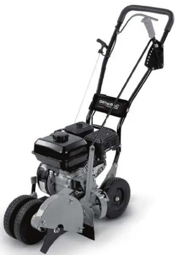
natural_image
Exterior view of a black and silver GENUAC lawn mower (no text or symbols visible)MODEL NUMBER: ____
SERIAL NUMBER:
DATE PURCHASED:
Register your Generac product at:
WWW.GENERAC.COM
1-888-545-6576
Original Instructions
SAVE THIS MANUAL FOR FUTURE REFERENCE
! WARNING
CANCER AND REPRODUCTIVE HARM
www.P65Warnings.ca.gov.
(000393a)
Table of Contents
Section 1: Safety Rules & General Information
Introduction ....1
Read This Manual Thoroughly ....1
Safety Rules ....1
How to Obtain Service ....1
General Hazards ......2
Exhaust and Fuel Hazards ....2
Fire Hazards ....3
Explosion Hazards ....3
Safety and Operating Decals 4
Section 2: General Information and Setup
Components and Locations ....5
Specifications 6
Emissions 6
Remove Contents from Carton 6
Assembling the Unit ....7
Installing Handlebar 7
Adding Engine Oil and Fuel 7
Engine Fluid Requirements 7
Adding Engine Oil 7
Adding Fuel 8
Spark Arrestor 8
Section 3: Operation
Operating Tips 9
Before Starting Engine 9
Starting the Engine 9
Stopping the Engine 9
Adjustments 9
Adjusting Edger Cutting Depth 9
Adjusting Blade Angle ....10
Adjusting Wheel Height for Curbs 10
Slopes ......10
Section 4: Maintenance and Troubleshooting
Maintenance ....11
Maintenance Schedule 11
Replacing the Belt ....12
Changing Engine Oil 12
Changing the Blade ....12
Servicing Spark Plug ....13
Cleaning the Air Filter ....13
Storage 14
Troubleshooting 15
This page intentionally left blank.
Section 1: Safety Rules & General Information
Introduction
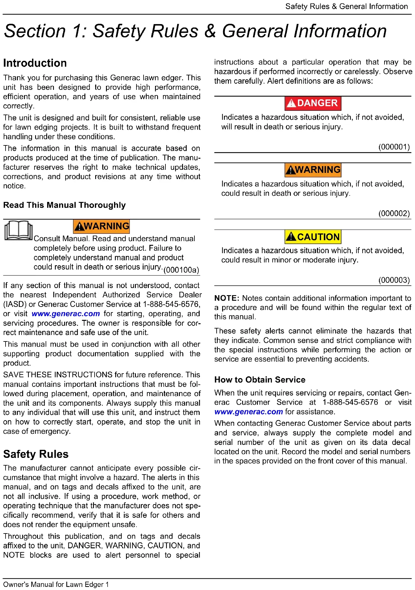
Thank you for purchasing this Generac lawn edger. This unit has been designed to provide high performance, efficient operation, and years of use when maintained correctly.
The unit is designed and built for consistent, reliable use for lawn edging projects. It is built to withstand frequent handling under these conditions.
The information in this manual is accurate based on products produced at the time of publication. The manufacturer reserves the right to make technical updates, corrections, and product revisions at any time without notice.
Read This Manual Thoroughly

WARNING
Consult Manual. Read and understand manual completely before using product. Failure to completely understand manual and product could result in death or serious injury.(000100a)
If any section of this manual is not understood, contact the nearest Independent Authorized Service Dealer (IASD) or Generac Customer Service at 1-888-545-6576, or visit www.generac.com for starting, operating, and servicing procedures. The owner is responsible for correct maintenance and safe use of the unit.
This manual must be used in conjunction with all other supporting product documentation supplied with the product.
SAVE THESE INSTRUCTIONS for future reference. This manual contains important instructions that must be followed during placement, operation, and maintenance of the unit and its components. Always supply this manual to any individual that will use this unit, and instruct them on how to correctly start, operate, and stop the unit in case of emergency.
Safety Rules
The manufacturer cannot anticipate every possible circumstance that might involve a hazard. The alerts in this manual, and on tags and decals affixed to the unit, are not all inclusive. If using a procedure, work method, or operating technique that the manufacturer does not specifically recommend, verify that it is safe for others and does not render the equipment unsafe.
Throughout this publication, and on tags and decals affixed to the unit, DANGER, WARNING, CAUTION, and NOTE blocks are used to alert personnel to special
instructions about a particular operation that may be hazardous if performed incorrectly or carelessly. Observe them carefully. Alert definitions are as follows:
DANGER
Indicates a hazardous situation which, if not avoided, will result in death or serious injury.
(000001)
WARNING
Indicates a hazardous situation which, if not avoided, could result in death or serious injury.
(000002)
CAUTION
Indicates a hazardous situation which, if not avoided, could result in minor or moderate injury.
(000003)
NOTE: Notes contain additional information important to a procedure and will be found within the regular text of this manual.
These safety alerts cannot eliminate the hazards that they indicate. Common sense and strict compliance with the special instructions while performing the action or service are essential to preventing accidents.
How to Obtain Service
When the unit requires servicing or repairs, contact Generac Customer Service at 1-888-545-6576 or visit www.generac.com for assistance.
When contacting Generac Customer Service about parts and service, always supply the complete model and serial number of the unit as given on its data decal located on the unit. Record the model and serial numbers in the spaces provided on the front cover of this manual.
General Hazards
WARNING
Personal injury. Never remove, alter, or tamper with safety devices. Do not operate unit without safety equipment in place. Doing so could result in death, serious injury, property damage, or equipment damage. (000403)
WARNING
Personal injury. Keep out of reach of children. Failure to do so could result in death or serious injury.
(000128a)

!WARNING
Vision loss. Eye protection is required when servicing unit. Failure to do so could result in vision loss or serious injury. (000377)
WARNING
Personal injury and equipment damage. Do not tamper with engine governed speed. Operating engine too fast or slow increases the risk of injury or permanent engine damage. (000254)

!WARNING
Moving Parts. Do not wear jewelry when starting or operating this product. Wearing jewelry while starting or operating this product could result in death or serious injury. (000115)

WARNING
Moving Parts. Keep clothing, hair, and appendages away from moving parts. Failure to do so could result in death or serious injury. (000111)

!WARNING
Hot Surfaces. When operating machine, do not touch hot surfaces. Keep machine away from combustibles during use. Hot surfaces could result in severe burns or fire. (000108)

WARNING
Risk of Fire. Hot surfaces could ignite combustibles, resulting in fire. Fire could result in death or serious injury. (000110)
!WARNING
Risk of injury. Do not operate or service this machine if not fully alert. Fatigue can impair the ability to operate or service this equipment and could result in death or serious injury. (000215a)

WARNING
Hearing Loss. Hearing protection is recommended when using this machine. Failure to wear hearing protection could result in permanent hearing loss. (000107)
WARNING
Personal injury. Wear sturdy shoes with no-slip tread, long pants, and gloves when operating this unit. Failure to do so could result in death or serious injury. (000492)
WARNING
Personal injury. Operate only in daylight or in area lit by artificial light. Failure to do so could result in death, serious injury, property or equipment damage. (000620)
Exhaust and Fuel Hazards

DANGER
Asphyxiation. The exhaust system must be properly maintained. Do not alter or modify the exhaust system as to render it unsafe or make it noncompliant with local codes and/or standards. Failure to do so will result in death or serious injury. (000179b)

DANGER
Asphyxiation. Running engines produce carbon monoxide, a colorless, odorless, poisonous gas. Carbon monoxide, if not avoided, will result in death or serious injury. (000103)

DANGER
Explosion and Fire. Fuel and vapors are extremely flammable and explosive. Store fuel in a well ventilated area. Keep fire and spark away. Failure to do so will result in death or serious injury. (000143)

! DANGER
Explosion and Fire. Do not overfill fuel tank. Overfilling may cause fuel to leak and ignite or explode, resulting in death or serious injury. (000204)

DANGER
Risk of fire. Allow fuel spills to completely dry before starting engine. Failure to do so will result in death or serious injury. (000174)

WARNING
Fire risk. Fuel and vapors are extremely flammable. Do not operate indoors. Doing so could result in death, serious injury, or property or equipment damage. (000281)

WARNING
Explosion and fire risk. Do not smoke near unit. Keep fire and spark away. Failure to do so could result in death, serious injury, or property or equipment damage. (000282)

WARNING
Explosion and Fire. Do not smoke while refueling unit. Failure to do so could result in death, serious injury, or property or equipment damage. (000284a)
Fire Hazards

DANGER
Risk of fire. Allow fuel spills to completely dry before starting engine. Failure to do so will result in death or serious injury. (000174)

WARNING
Risk of Fire. Verify machine has properly cooled before installing cover and storing machine. Hot surfaces could result in fire. (000109)

!WARNING
Risk of fire. Never operate engine without the air cleaner installed. Operating engine without the air cleaner could result in death or serious injury. (000249)
Explosion Hazards

! DANGER
Explosion and fire. Fuel and vapors are extremely flammable and explosive. No leakage of fuel is permitted. Keep fire and spark away. Failure to do so will result in death or serious injury. (000192)

! WARNING
Risk of Fire. Hot surfaces could ignite combustibles, resulting in fire. Fire could result in death or serious injury. (000110)
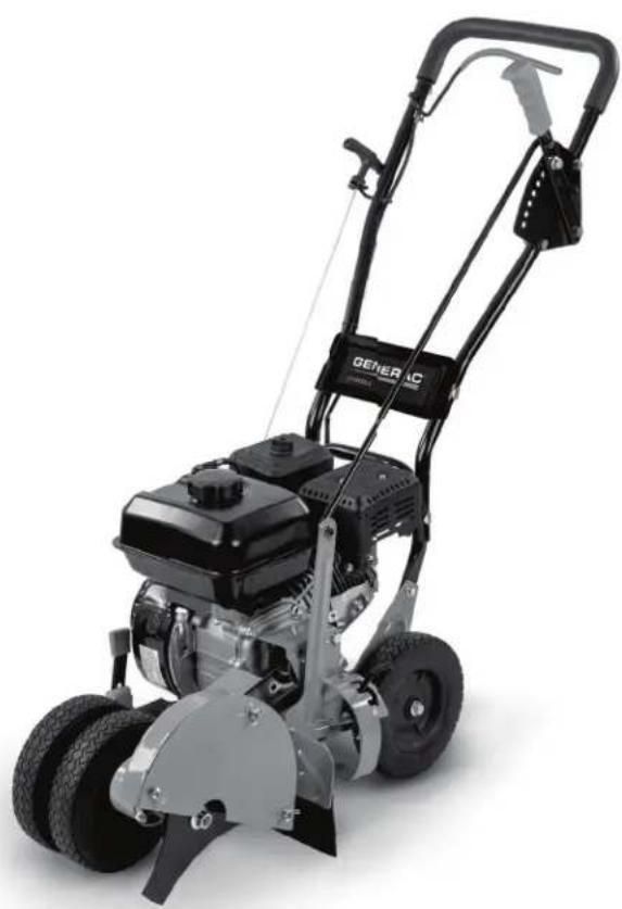
Safety and Operating Decals
See Figure 1-1. This unit features numerous safety and operating decals. These decals provide important operating instructions and warn of dangers and hazards. Replace damaged or missing safety and operating decals immediately. Decal part numbers can be found in the unit parts manual at www.generac.com.
011495
Figure 1-1. Safety and Operating Decal Locations
Section 2: General Information and Setup
Components and Locations

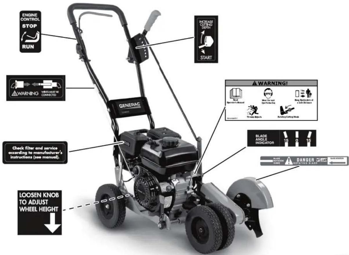
Figure 2-1. Features and Controls
A Depth control lever K Primer bulb
B Depth selector plate L Air filter
C Control rod M Flameout wire terminals
D Fuel cap and fill N Recoil starter handle
E Oil dipstick/fill cap P Start lever
F Blade guard Q Spark plug/spark plug wire
G Blade R Muffler
H Adjustable front wheels S Engine belt cover
J Adjustable rear wheel T Bevel adjustment lever
Specifications
| Engine | 4-stroke OHV |
| Engine speed 3000 rpm | |
| Displacement 163cc | |
| Torque rating 6.5 ft-lbs (8.8 Nm) gross torque per SAE J1940 | |
| Fuel capacity (qt / L) 3.5 / 3.3 | |
| Oil capacity (oz / mL) 19 / 562 | |
| Fuel type Unleaded gasoline | |
| Blade diameter (in / cm) 9 / 22.8 | |
| Cutting depth (in / mm) 0.0–3.0 / 0.0–76 | |
| Wheels (in / cm) | 8.0 / 20.3 |
| Handlebars | Straight |
| Machine dimensions (in / cm) | 45 x 19 x 39.5 / 114.3 x 48.3 x 100.3 |
| Machine weight (lbs / kg) | 71 / 32 |
Emissions
The United States Environmental Protection Agency (US EPA) (and California Air Resources Board (CARB), for engines/equipment certified to California standards) requires this engine/equipment to comply with exhaust and evaporative emissions standards. Locate the emissions compliance decal on the engine to determine applicable standards. See the included emissions warranty for emissions warranty information. Follow the maintenance specifications in this manual to ensure the engine complies with applicable emissions standards for the duration of the product's life.
Remove Contents from Carton
Proceed as follows to remove parts and unit from carton:
- Remove all parts and packaging components. Verify the following components are included:
| Part | Qty. |
| Edger | 1 |
| Owner's manual | 1 |
| Upper handlebar | 1 |
| Control rod | 1 |
| Hair pins | 2 |
| Plastic wing nuts (M8) | 2 |
| M8 x 35mm bolts | 2 |
| Wire tie | 1 |
| Spark plug socket wrench w/rod | 1 |
NOTE: Contact an IASD if any parts are damaged or missing.
- Cut all four vertical edges of the carton and lay side panels flat around edger.
- Remove any remaining packaging.
- Roll unit out from carton and place on a level surface.
Assembling the Unit
Installing Handlebar
Proceed as follows to install handlebar:
- See Figure 2-2. Assemble upper handlebar (A) to lower handlebar (B) with two bolts (C) and two plastic wing nuts (D). Firmly hand-tighten the wing nuts.
Figure 2-2. Assembling Handlebar
- Slide one end of control rod (E) into hole of depth control lever (F). Secure with hair pin (G).
- Slide other end of control rod through hole of quill arm support (H). Secure with hair pin.
- Attach recoil starter handle (J) through rope guide (K). Twist into position.
- Remove temporary insert from engine flameout wire terminal (L).
- Connect flameout wires from engine and handlebar (M). Use cable ties to secure loose flameout wire to handlebar.
Adding Engine Oil and Fuel
Engine Fluid Requirements
| Engine Oil | 0–100 °F (-17–38 °C): SAE 10W-3050–100 °F (10–38 °C): SAE 30For Service, SG, SH, SJ, or higher |
| Fuel | Unleaded gasolineMinimum 87 octane ratingUp to 10% ethanol (gasohol) is acceptableNon-ethanol premium fuel recommendedDO NOT use E85DO NOT use a gas oil mixture |
IMPORTANT NOTE: DO NOT modify engine to run on alternative fuels. Stabilize fuel prior to storage.
Engine oil capacity is 19 oz (562 mL).
Fuel tank capacity is 3.5 qt (3.3 L).
Adding Engine Oil

WARNING
Fire and explosion risk. Keep spark and flame away from liquid and vapor. Do not smoke while using. Doing so could result in death, serious injury, or equipment damage. (000341)
WARNING
Skin irritation. Avoid prolonged or repeated contact with used motor oil. Used motor oil has been shown to cause skin cancer in laboratory animals. Thoroughly wash exposed areas with soap and water. (000210)
CAUTION
Engine damage. Verify proper type and quantity of engine oil prior to starting engine. Failure to do so could result in engine damage.
(000135)
IMPORTANT NOTE: Unit is shipped without oil in engine. Traces of oil may be in reservoir from factory testing. Oil must be added prior to initial operation.
Proceed as follows to add engine oil:
- Place edger on level surface, and verify the adjustable wheel heights are set so the main frame of the edger is level.
- Verify oil fill area is clean.
- See Figure 2-3. Remove oil dipstick/fill cap (A) and wipe oil dipstick clean.
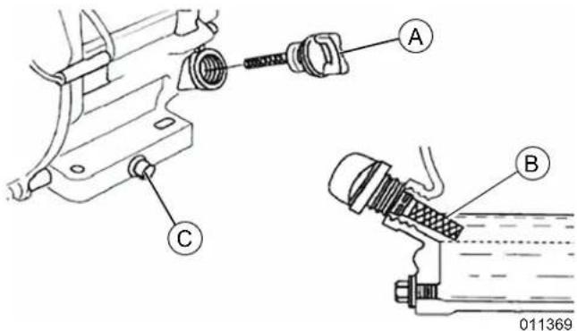
Figure 2-3. Adding Engine Oil
- Add recommended oil slowly. Use a funnel or nozzle to reduce spillage.
IMPORTANT NOTE: Do not overfill. Check oil level frequently while filling.
-
Insert oil dipstick into oil filler neck. Do not screw in. Remove oil dipstick and verify oil level is within safe operating range (B) on oil dipstick.
-
Install oil dipstick/fill cap and hand-tighten.
- Clean up any spilled oil.
Adding Fuel

DANGER
Explosion and Fire. Fuel and vapors are extremely flammable and explosive. Add fuel in a well ventilated area. Keep fire and spark away. Failure to do so will result in death or serious injury. (000105)

DANGER
Explosion and Fire. Do not overfill fuel tank. Fill to 1/2 inch from top of tank to allow for fuel expansion. Overfilling may cause fuel to spill onto engine causing fire or explosion, which will result in death or serious injury. (000166b)

WARNING
Explosion and Fire. Do not smoke while refueling unit. Failure to do so could result in death, serious injury, or property or equipment damage. (000284a)
IMPORTANT NOTE: It is important to prevent gum deposits from forming in fuel system parts such as the fuel hose or fuel tank during storage. Alcohol-based fuels (gasohol, ethanol, or methanol) can attract moisture, which leads to separation and formation of acids during storage. Acidic gas can damage an engine fuel system. The fuel system must be emptied before storage of 30 days or longer to avoid engine problems. Never use engine or carburetor cleaner products in the fuel tank as permanent damage may occur.
NOTE: Never use contaminated gasoline or mixed gasoline with oil. Do not allow dust, foreign matter or water to enter into the fuel tank.
Proceed as follows to add fuel:
- Place unit on a firm, level surface in a well ventilated area.
- Verify unit is OFF and cooled for a minimum of two minutes.
- Clean area around fuel cap and remove cap slowly.
- Slowly add recommended fuel. Do not overfill.
- Install fuel fill cap.
- Clean up any spilled fuel.
NOTE: Allow spilled fuel to evaporate before starting unit.
Spark Arrestor
WARNING
Personal injury. Before performing any maintenance procedure or inspection, stop the engine, and allow all parts to cool. Disconnect spark plug wire and keep spark plug wire away from spark plug. Failure to do so could result in serious injury. (000688)
This unit is equipped with a spark arrestor. Under California law, and the laws of some other states, operating an internal combustion engine using hydrocarbon fuels without an engine spark arrester is not permitted. This also applies to operation on US Forest Lands. All units shipped to California, New Mexico, and Washington State are provided with spark arresters. Failure of the owner or operator to maintain this equipment in compliance with state regulations is a misdemeanor under California law and may be in violation of other state and/or federal regulations. Contact the State Park Association or the appropriate state organization for specific information in your area.
Section 3: Operation
Operating Tips
- Operate the unit in dry conditions. Wet ground becomes packed around blade, which can cause premature belt wear and decreased performance.
- Remove packed dirt and debris from blade for optimal performance.
- First cut at shallow depths, then cut at greater depths until desired depth is reached. Do not overload the unit by cutting deep.
- Customize the edging by varying the amount of passes and distance between blade and edge of sidewalk, driveway, or curb.
Before Starting Engine
WARNING
Personal injury. Never remove, alter, or tamper with safety devices. Do not operate unit without safety equipment in place. Doing so could result in death, serious injury, property damage, or equipment damage. (000403)
CAUTION
Equipment damage. Clear the engine of grass and debris before each use. Failure to do so could result in engine damage.
(000490)
IMPORTANT NOTE: Unit is shipped without oil. Add engine oil before starting. See Adding Engine Oil for instructions.
- Check engine oil level.
- Check fuel level.
- Inspect unit for damage.
- Remove any debris buildup from the top of the engine, the underside of the machine, and the muffler.
- Verify all fasteners are correctly tightened.
- Verify flameout wire terminals are connected.
- Verify spark plug wire is connected.
- Unit has been moved to the work site.
Starting the Engine
CAUTION
Equipment damage. Do not leave unit operating unattended at any time. Shut down engine prior to leaving. Failure to do so could result in property or equipment damage. (000734)
Proceed as follows to start a cold engine:
- Verify unit is level.
- See Operating Tips.
- Set depth control lever to START.
- Starting a cold engine only: Push primer bulb three times. Wait two seconds between each push.
- Firmly hold recoil starter handle with left hand and pull start lever against handle.
- Pull recoil starter handle slowly until resistance is felt. Then quickly pull recoil starter handle to completely unwind starter rope. Do not allow starter rope to snap back. Slowly rewind starter rope while holding recoil starter handle.
NOTE: The engine should start within one to two pulls. See Troubleshooting if unit fails to start after five attempts.
Stopping the Engine
Release start lever to ground out engine through the flameout wire, which causes the engine to stop.
Adjustments
WARNING
Accidental startup. Engine must be off before adjusting any controls or attachments. Failure to do so could result in death, serious injury, or property or equipment damage. (000735)
Adjusting Edger Cutting Depth
IMPORTANT NOTE: Do not overload edger capacity. Make multiple passes when edging deeper settings, starting at a shallow depth.
Move depth control lever forward to increase edge cutting depth. There are six cutting depth settings from approximately ground level to 3.0 in (76 mm) deep.
Adjusting Blade Angle
Blade can be adjusted 15^ from vertical in both directions to provide a beveled cut. This cuts grass further away from the sidewalk or driveway, reducing the need to edge as often. Use the beveled edge at a deep depth to cut a trench into ground.
Proceed as follows to adjust blade angle:
- Stop engine and allow it to cool.
- See Figure 3-1. Disengage the index lever (A) and move it to the desired notch ( 15^ , 0^ , or -15^ ).
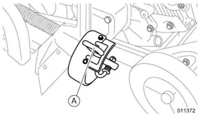
natural_image
Technical diagram of a mechanical assembly with labeled component A (no readable text or symbols)Figure 3-1. Index Lever
- Line up edger before starting the engine.
Adjusting Wheel Height for Curbs
Proceed as follows to adjust wheel height for edging curbs:
- Stop engine and allow it to cool.
- See Figure 3-2. Loosen front wheel knob (B).
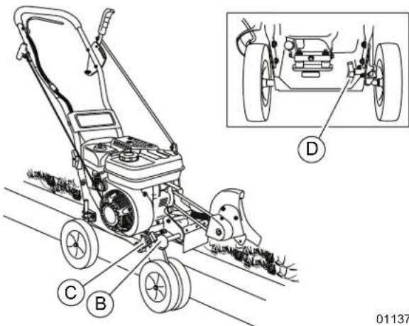
Figure 3-2. Adjusting Wheel Height
- Slide wheels to the right, enough to clear the curb and balance the unit.
- Securely tighten front wheel knob.
-
Use front wheel adjustment lever (C) to lower front wheels enough to level unit.
-
Loosen rear wheel knob (D).
- Lower right rear wheel enough to level unit.
- Securely tighten rear wheel knob.
Slopes
!WARNING
Personal injury. Use caution when operating unit over uneven terrain or slopes. Failure to do so could result in death, serious injury, equipment or property damage. (000460)
- This unit can be used on slopes up to 15^ . Continuous use on slopes steeper than 15^ could result in engine damage.
- Avoid sudden turns or maneuvers.
Section 4: Maintenance and Troubleshooting
Maintenance
Regular maintenance will improve performance and extend engine/equipment life. Generac Power Systems, Inc. recommends that all maintenance work be performed by an Independent Authorized Service Dealer (IASD). Regular maintenance, replacement, or repair of the emissions control devices and systems may be performed by any repair shop or person of the owner's choosing. To obtain emissions control warranty service free of charge, the work must be performed by an IASD. See the emissions warranty.
Maintenance Schedule
WARNING
Risk of injury. Do not operate or service this machine if not fully alert. Fatigue can impair the ability to operate or service this equipment and could result in death or serious injury. (000215a)
WARNING
Accidental Start-up. Disconnect spark plug wire when working on unit. Failure to do so could result in death or serious injury.
(000102)

WARNING
Hot Surfaces. When operating machine, do not touch hot surfaces. Keep machine away from combustibles during use. Hot surfaces could result in severe burns or fire. (000108)
| Procedure | Before Each Use | Every 10 Hours | Every 25 Hours | Every 50 Hours | Every 100 Hours |
| Check fuel and engine oil level | ● | ||||
| Clean engine exterior, cooling fins, and remove collected grass* | ● | ||||
| Inspect flameout wire connections | ● | ||||
| Inspect general equipment condition | ● | ||||
| Inspect drive belt (replace if necessary) | ● | ||||
| Lubricate all pivot points | ● | ||||
| Inspect fasteners | ● | ||||
| Inspect blade for wear or damage (replace if necessary) | ● | ||||
| Inspect spark plug (replace if necessary) | ● | ||||
| Inspect fuel line (replace if necessary) | ● | ||||
| Lubricate wheel axle shaft | ● | ||||
| Clean air filter (replace if necessary)** | ● | ||||
| Change engine oil | 1^st time 5–8 hours | ● | |||
| Replace spark plug | ● | ||||
| Clean combustion deposits from cylinder, piston, and valves | ● | ||||
| * Cleaning the top of the engine during use is critical for sufficient air flow. ** Change more frequently if used in extremely dusty or dirty conditions. | |||||
Replacing the Belt
WARNING
Accidental Start-up. Disconnect spark plug wire when working on unit. Failure to do so could result in death or serious injury.
(000102)
Proceed as follows to replace the belt:
- Shut down engine if running. Allow several minutes for unit to cool.
- Disconnect spark plug wire and place it where it will not contact spark plug.
- Remove control rod.
- See Figure 2-1. Remove two rear guard bolts to remove engine pulley cover (S).
- See Figure 4-1. Remove two front guard screws (A) and belt guard (B).
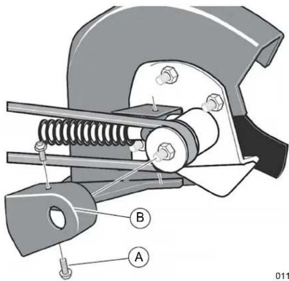
011386
Figure 4-1. Remove Front Screws and Belt Guard
- Remove old belt from engine and quill assembly pulleys.
-
Reverse the above steps to install replacement belt.
-
Tighten rear guard bolts to 13–16 ft-lbs (18–22 Nm).
- Tighten front guard screws to 4–6 ft-lbs (6–8 Nm).
Changing Engine Oil
WARNING
Skin irritation. Avoid prolonged or repeated contact with used motor oil. Used motor oil has been shown to cause skin cancer in laboratory animals. Thoroughly wash exposed areas with soap and water. (000210)
CAUTION
Engine damage. Verify proper type and quantity of engine oil prior to starting engine. Failure to do so could result in engine damage.
(000135)
NOTE: Drain oil when engine is warm. Warm oil drains more completely.
Proceed as follows to change engine oil:
- Shut off engine and allow unit to cool.
- Disconnect spark plug wire from spark plug and place it where it will not contact spark plug.
- Lower front wheel height to raise front end of unit.
- See Figure 2-3. Place suitable container below oil drain plug (C).
- Remove oil dipstick/fill cap.
- Remove oil drain plug and washer.
- Drain oil. Dispose of used oil according to local, national, or state laws.
- Install and tighten oil drain plug and washer.
- Fill engine with oil according to Adding Engine Oil.
- Install oil dipstick.
- Connect spark plug wire to spark plug.
Changing the Blade
NOTE: Do not sharpen the blade.
NOTE: Replacing blade requires two 12 in (30.5 cm) adjustable wrenches or two 0.75 in (19 mm) wrenches.
Proceed as follows to replace the blade:
- Shut off engine and allow unit to cool.
- Disconnect spark plug wire and place it where it will not contact spark plug.
- See Figure 4-2. Remove blade locknut (A) holding blade to the drive shaft. Use a wrench to hold nut behind the blade still while removing the blade locknut.
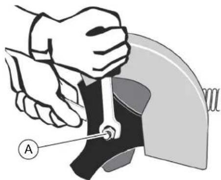
natural_image
Illustration of a hand using a tool to adjust or install a mechanical component, labeled with point A (no text or symbols present)011384
Figure 4-2. Removing Blade
- Remove blade.
- Reverse the above steps to install new blade.
NOTE: Tighten blade locknut to 35–45 ft-lbs (47–61 Nm).
Servicing Spark Plug
NOTE: Use only the recommended spark plug or spark plug with the same temperature range.
Spark plug gap must be correct for efficient operation. Proceed as follows to service the spark plug:
- Shut off engine and allow unit to cool.
- Disconnect spark plug wire from spark plug and place it where it will not contact spark plug.
- Clean area around spark plug.
- Remove spark plug using spark plug wrench and rod.
- Inspect spark plug for cracks or damage. Replace spark plug if necessary.
-
Clean the electrodes with a metal brush and remove any build up.
-
See Figure 4-3. Measure spark plug clearance with a feeler gauge. The clearance should be 0.028–0.031 in (0.7–0.8 mm).
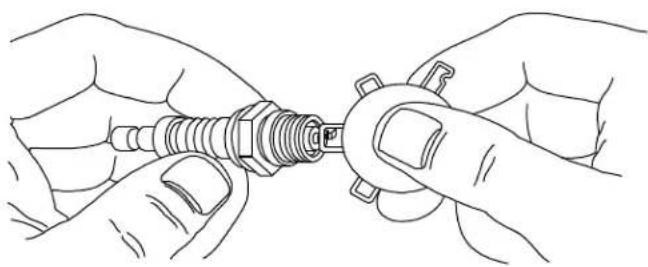
natural_image
Line drawing of two hands adjusting a screw component (no text or symbols)000211
Figure 4-3. Spark Plug
- Replace spark plug if electrodes are pitted, burned, or porcelain is cracked. Use only a TORCH F7RTC or equivalent.
- Install spark plug and tighten to 18–22 ft-lbs (25–30 Nm) using spark plug wrench.
Cleaning the Air Filter

WARNING
Explosion and fire. Never clean air filter element with gasoline or low flash-point detergents. Doing so could result in death, serious injury, or equipment damage. (000580)
Proceed as follows to clean or replace air filter:
- Remove outer wing nut, washer, and air filter cover.
- Remove inner wing nut and air filter.
IMPORTANT NOTE: Do not allow dirt or debris to enter the carburetor.
- Separate outer foam element from inner paper element.
- Inspect inside of paper element for dirt or debris.
- Inspect both elements for tears or damage.
NOTE: If inner paper element is dirty, or if either element is torn, replace air filter.
- Wash outer foam element in household detergent and water, or in a nonflammable or high flash-point solvent. Soak foam element in clean engine oil, and squeeze out excess oil.
- Lightly tap inner paper element against hard surface to remove excess dirt, or blow compressed air through the air filter from the inside out.
NOTE: Do not brush dirt off paper element, this will embed dirt into the fibers.
- Install cleaned foam element onto inner paper element.
- Reverse steps 1 and 2 to install clean air filter and air filter cover onto the unit.
Storage

DANGER
Explosion and Fire. Fuel and vapors are extremely flammable and explosive. Store fuel in a well ventilated area. Keep fire and spark away. Failure to do so will result in death or serious injury.
(000143)

! DANGER
Explosion and Fire. Drain fuel in a well ventilated area, into an approved container only after engine has cooled. Failure to do so will result in death or serious injury.
(000180)

WARNING
Risk of Fire. Verify machine has properly cooled before installing cover and storing machine. Hot surfaces could result in fire.
(000109)
NOTE: A yearly checkup or tune-up by an IASD is recommended for optimal performance.
Proceed as follows to put unit in storage for thirty days or more:
- Run the engine until it is out of fuel.
- Change engine oil. See Changing Engine Oil.
- Remove spark plug from cylinder. Pour 1 oz (29.5 mL) oil into cylinder. Slowly pull recoil handle so oil will protect cylinder. Install new spark plug in cylinder. Pull starter handle slowly a few times to distribute oil. Pull recoil slowly until resistance is felt to close cylinder valves. Do not attach spark plug wire.
- Clean edger. Remove all dirt, leaves, debris, grease, etc. from edger, including cylinder cooling fans, recoil starter cover holes, under fuel tank, and under muffler.
- Inspect edger for damage. Have damaged parts replaced if necessary.
- Inspect hardware, and tighten any loose fasteners.
- Store unit in building with good ventilation, away from spark such as space heaters or pilot lights.
- Cover edger with a breathable material. Do not use plastic as moisture can collect underneath and cause rusting.
Troubleshooting
| Problem Cause Correction | ||
| Recoil cord will not pull out or is difficult to pull | Seized engine. Check engine | oil level. Contact an IASD. |
| Oil compression lock. | Remove the spark plug, hold a rag over the spark plug hole, and pull recoil cord several times to blow out any oil in the cylinder. Wipe off the spark plug and reinstall it. | |
| Broken or jammed recoil cord. | Turn engine pulley by hand with the spark plug removed. If the engine pulley turns the recoil is broken or jammed. Contact an IASD. | |
| Engine will not start.See engine owner's manual for engine-specific procedures. | No or insufficient fuel. Fill fuel | reservoir. |
| Spark plug wire not attached. | Verify spark plug wire is attached correctly. | |
| Insufficient or dirty engine oil. | Verify the engine has the right amount of clean oil. If oil is dirty, change it. SeeChanging Engine Oil. | |
| Dirty or degraded fuel. | Fuel must be fresh, clean, and unleaded with no more than 10% ethanol. If the fuel is old, change it. Use a fuel stabilizer if fuel will be kept longer than one month. | |
| Dirty or clogged air filter. | Verify the air filter is clean. If the air filter is dirty, change it according to the engine owner's manual. | |
| Broken or faulty spark plug. | Verify the spark plug is clean. Replace spark plug if dirty or cracked. If spark plug is oily, leave it out, hold a rag over spark plug hole and crank engine several times to blow out any oil in the cylinders. Wipe off spark plug and install. | |
| Drive safety control levers activated. | Both drive safety control levers must be in neutral to start engine. | |
| Engine hard to start, or starts and runs rough | Old or degraded fuel. | Drain fuel and replace with fresh fuel. Use fuel stabilizer at end of season. |
| Broken or faulty spark plug. | Verify the spark plug is clean. Replace spark plug if dirty or cracked. If spark plug is oily, leave it out, hold a rag over spark plug hole and crank engine several times to blow out any oil in the cylinders. Wipe off spark plug and install. | |
| Dirty or clogged air filter. Clean or replace air filter. | ||
| Engine smokes | Insufficient engine oil. Check | engine oil level and adjust as needed. |
| Slope too great. | Verify unit is not being operating on too great of an incline.SeeSlopesfor more information. | |
| Dirty or clogged air filter. | Verify the air filter is clean. If the air filter is dirty, change it according to the engine owner's manual. | |
| Incorrect engine oil. | Verify correct oil weight is being used. Engine may smoke if oil is too light for ambient temperature. | |
| Engine lacks power or is not running smoothly.See engine owner's manual for engine-specific procedures. | Dirty or clogged air filter. | Verify air filter is clean. If air filter is dirty, change it according to the engine owner's manual. |
| Dirty or oily spark plug connection. | Remove spark plug wire and dry connection with a rag. | |
| Dirty or cracked spark plug. | Inspect spark plug, change as necessary. If spark plug is oily, leave it out, hold a rag over the plug hole and crank engine several times to blow out any oil in the cylinders. Wipe off plug and install. | |
| Dirty or degraded fuel. | Drain fuel and replace with fresh fuel. Use a fuel stabilizer if the gas will be kept longer than one month. | |
| Incorrect amount of engine oil. | Verify oil level. If the oil is dirty, change it. See Changing Engine Oil. | |
| Incorrect carburetor adjustment. | Contact an IASD. | |
| Blade set too deep. Raise blade for shallow edging. | ||
| Dirty fuel tank. Remove and clean fuel tank. | ||
| Engine runs well but blade does not spin | Drive belt broken or off pulleys. | Install or change drive belt. See Replacing the Belt. |
| Overstretched drive belt slipping on pulleys. | Change drive belt. See Replacing the Belt. | |
| Inadequate torque on blade nut allowing blade to stop when making contact with ground. | Tighten blade nut to approximately 35–45 ft-lbs (47.5–61.0 Nm). | |
| Excessive soil build up in debris guard. | Turn engine off. Remove debris cover and remove any soil build up around blade inside debris guard. | |
This page intentionally left blank.
This page intentionally left blank.
Part No. A0000930852 Rev. B 11/19/2020
©2020 Generac Power Systems, Inc.
All rights reserved.
Specifications are subject to change without notice.
No reproduction allowed in any form without prior written
consent from Generac Power Systems, Inc.
GENERAC®
Generac Power Systems, Inc.
S45 W29290 Hwy. 59
Waukesha, WI 53189
1-888-GENERAC (1-888-436-3722)
www.generac.com
Manual del usuario
Bordeadora GC8000E
natural_image
Exterior view of a GERAAC lawn mower with visible blade and mounting bracket (no text or symbols)MODELO:
SERIE:
FECHA DE COMPRA:
Figura 2-2. Montaje del manillar
Figura 2-3. Añadir aceite de motor
natural_image
Technical diagram of a mechanical assembly with labeled component A (no readable text or symbols)Figura 3-1. Palanca indicadora
011386
Figura 4-1. Extraer tornillos delanteros y protector de correa
natural_image
Illustration of a hand holding a tool interacting with a mechanical component, labeled 'A' (no text or symbols on the diagram itself)011384
Figura 4-2. Retirar la cuchilla
natural_image
Line drawing of hands connecting a screw to a nut (no text or symbols)000211
Figura 4-3. Bujía
©2020 Generac Power Systems, Inc.
natural_image
Exterior view of a black and silver Generac lawn mower (no text or symbols visible)MODÈLE :
N° DE SÉRIE : ____
DATE D'ACHAT :
natural_image
Illustration of a hand using a tool to adjust or install a mechanical component, labeled with point A (no text or symbols present)011384
natural_image
Line drawing of hands connecting a screw to a pin (no text or symbols)000211
Figure 4-3. Bougie
©2020 Generac Power Systems, Inc.
- Owner's Manual GC8000E Lawn Edger
- ! WARNING
- Table of Contents
- Section 1: Safety Rules & General Information
- Section 2: General Information and Setup
- Section 3: Operation
- Section 4: Maintenance and Troubleshooting
- This page intentionally left blank.
- Introduction
- Read This Manual Thoroughly
- WARNING
- Safety Rules
- DANGER
- CAUTION
- How to Obtain Service
- General Hazards
- !WARNING
- Exhaust and Fuel Hazards
- ! DANGER
- Fire Hazards
- Explosion Hazards
- Safety and Operating Decals
- Components and Locations
- Emissions
- Remove Contents from Carton
- Assembling the Unit
- Installing Handlebar
- Adding Engine Oil and Fuel
- Adding Engine Oil
- Adding Fuel
- Spark Arrestor
- Operating Tips
- Before Starting Engine
- IMPORTANT NOTE: Unit is shipped without oil. Add engine oil before starting. See Adding Engine Oil for instructions.
- Starting the Engine
- Stopping the Engine
- Adjustments
- Adjusting Edger Cutting Depth
- IMPORTANT NOTE: Do not overload edger capacity. Make multiple passes when edging deeper settings, starting at a shallow depth.
- Adjusting Blade Angle
- Adjusting Wheel Height for Curbs
- Slopes
- Maintenance
- Maintenance Schedule
- Replacing the Belt
- Changing Engine Oil
- Changing the Blade
- Servicing Spark Plug
- Cleaning the Air Filter
- Storage
- Manual del usuario
- Bordeadora GC8000E
Brand : Generac
Model : GC8000E
Category : Lawn mower