
GNULQ - Water Filtration GE - Free user manual and instructions
Find the device manual for free GNULQ GE in PDF.
| Product Type | Under-Sink Filtration System |
| Brand | GE |
| Model | GNULQ |
| Usage | Cold water only (1-38°C) |
| Certified Capacity | 2000 gallons (7571 liters) or 6 months |
| Flow Rate | 2 GPM (7.6 L/min) |
| Maximum Pressure | 100 psi (6.9 bar) |
| Guaranteed Reduction | Chlorine >97%, Class I Particles >99.8% |
| Standards | NSF/ANSI 42, CSA B483.1 |
| Power Supply | 2 AAA 1.5V batteries (included) |
| Connections | 3/8 in inlet/outlet, adapters included |
| Material | Plastic (head/holder), PE tubing |
| Installation | Vertical or horizontal (not upside down) |
| Maintenance | Cartridge replacement every 6 months |
| Replaceable Parts | GXULQR cartridge, timer, seals |
| Warranty | 1 year (except cartridge and batteries: 30 days) |
| Included Accessories | Cartridge, head/holder, 6 ft tubing, adapters, timer, screws |
| Approximate Dimensions | Height 30 cm, width 10 cm, depth 10 cm |
| Approximate Weight | 1 kg (without water) |
Frequently Asked Questions - GNULQ GE
User questions about GNULQ GE
0 question about this device. Answer the ones you know or ask your own.
Ask a new question about this device
Download the instructions for your Water Filtration in PDF format for free! Find your manual GNULQ - GE and take your electronic device back in hand. On this page are published all the documents necessary for the use of your device. GNULQ by GE.
USER MANUAL GNULQ GE
Installation Instructions
Kitchen and Bath Main Faucet Filtration System – GXULQ/GNULQ
SAFETY PRECAUTIONS
- Check with your state and local public works department for plumbing and sanitation codes. You must follow these guidelines as you install the Kitchen and Bath Main Faucet Filtration System. Using a qualified installer is recommended.
- Be sure the water supply conforms with the Performance Data. If the water supply conditions are unknown, contact your municipal water company.
⚠ WARNING — Do not use with water that is microbiologically unsafe or of unknown quality without adequate disinfection before or after the system.
- It is highly recommended that a water shut-off valve be placed directly upstream of your Kitchen and Bath Main Faucet Filtration System.
PARTS INCLUDED
- Filter Cartridge
- Filter Head/Bracket
- 6 Feet of 3/8" Tubing
- 3/8" × 1/2" Faucet Adapter
• 3/8" Compression Hex Nut - 3/8" Ferrule
- 3/8" Tube Insert
- Mounting Screws
• 1/2" Compression to 3/8" Adapter
- 7/16" Compression to 3/8" Adapter
Optional accessories are available (Visa, MasterCard or Discover cards accepted) by visiting our Website at ge.com or from Parts and Accessories, call 800.626.2002 (U.S.) or 800.663.6060 (Canada).
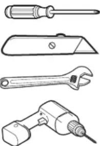
TOOLS YOU WILL NEED
Phillips-Head Screwdriver
Utility Knife
Adjustable Wrench
Drill with 1/8" Drill Bit
natural_image
Line drawings of four different types of wrenches and screwdriver (no text or symbols)PROPER INSTALLATION
This Kitchen and Bath Main Faucet Filtration System must be properly installed and located in accordance with the Installation Instructions before it is used.
- Check with your local public works department for plumbing codes. You must follow their guides as you install the Kitchen and Bath Main Faucet Filtration System.
- Use the Kitchen and Bath Main Faucet Filtration System on a potable safe-to-drink, home COLD water supply only. The filter cartridge will not purify water or make unsafe water safe to drink. DO NOT use on HOT water (100°F max).
- Protect the Kitchen and Bath Main Faucet Filtration System and piping from freezing. Water freezing in the system will damage it.
- Your Kitchen and Bath Main Faucet Filtration System will withstand up to 100 psi water pressure. If your house water supply pressure is higher than 100 psi during the day (it may reach higher levels at night), install a pressure reducing valve before the system is installed.
- Do not install on HOT WATER. The temperature of the water supply to the Kitchen and Bath Main Faucet Filtration System must be between the minimum of 34°F and the maximum of 100°F. See the Performance Data section.
- Do not install the Kitchen and BathMain Faucet Filtration System using copper solder fittings. The heat from the soldering process will damage the unit.
⚠ WARNING – Discard all unused parts and packaging material after installation. Small parts remaining after installation could be a choke hazard.
- Do not install filter in an outside location or anywhere it will be exposed to sunlight.

System is Tested and Certified by NSF International against NSF/ANSI Standard 42 for the reduction of Chlorine, Taste and Odor and Particulates Class I and against CSA B483.1.
Installation Instructions
CARTRIDGE SPECIFICATIONS
Performance Data - Filtration System GXULQ Using Filter GXULQR
This System has been tested according to NSF/ANSI 42 for the reduction of the substances listed below. The concentration of the indicated substances in water entering the system was reduced to a concentration less than or equal to the permissible limit for water leaving the system, as specified in NSF/ANSI 42.
■Act ual performance may vary with local water conditions.
■ Do not use with water that is microbiologically unsafe or with water of unknown quality without adequate disinfection before or after the system.
Standard No. 42: Aesthetic Effects
| Parameter | USEPA MCL | Influent Challenge Concentration | Influent Average | Effluent | % Reduction | Reduction Requirement | ||
| Average | Maximum | Average | Minimum | |||||
| Chlorine taste and odor | — | 2.0 mg/L ± 10% | 1.9 mg/L | <0.05 mg/L | 0.05 mg/L | >97.4% | 97.4% | ≥50% |
| Particulate, Class I particles 0.5 to <1um** | — | ≥10000 particles/mL | 10333333 #/mL | 20,500 #/mL | 41,000 #/mL | 99.8% | 99.6% | ≥85% |
*Tested using a flow rate of 2 gpm (7.6 l/min); pressure of 60 psig; pH of 7.5 ± 0.5; temp. of 68° ± 5°F (20° ± 3°C)
**Measurement in particles/mL. Particles used were 0.5–1 microns.
Operating Specifications
Capacity: certified for up to 2000 gallons (7,571 l); up to six months
Pressure requirement: 20-100 psi (1.4-6.9 bar)
Temperature: 34°-100°F (1.1°-38°C)
STEP-BY-STEINSTALLATION INSTRUCTIONS
Installation Overview
NOTE: Be sure to allow a minimum space of 12 " -2" under the system for removing the filter cartridge. If you have copper tubing with 3/8" compression fittings, you'll need to follow Step 3 Option B (Optional Installation).
3/8" × 1/2" Push to
Connect Adapter
Filter Head/
Bracket
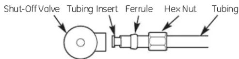
Tubing insert
Hex nut
IN
Ferrule
OUT
HOT COLD
Shut-Off Valve
OUT
IN
Filter
Cartridge
HOT COLD
Optional installation
FILTER CARTRIDGE REPLACEMENT
Replacement Filter Canister/Estimated Replacement Costs
GXULQR—Replacement filter canister \$29-34
For replacement parts, call toll-free 800.626.2002 (U.S.),
800.663.6060 (Canada-English), 800.361.3869 (Canada-French)
TO REMOVE FILTER:
- Turn filter 1/4 turn to the left. The top surface of the filter will move away from the bottom of the head. Pull the filter down to remove.
FILTER CARTRIDGE REPLACEMENT (cont.)
TO REPLACE FILTER:
A Push filter into the filter head/bracket. Turn filter 1/4 turn to the right until it stops. The top surface of the filter will be flush with the bottom of the filter head/bracket when fully installed.
NOTE: When correctly installed, the label will face out.
B Turn on the cold water faucet to flush the filter for 5 minutes to remove air.
C Change the batteries in the timer.
NOTE: Remove the water in the line to minimize the water released during filter cartridge replacement. Turn off the cold water supply valve and turn on the faucet for 5 seconds.
INSTALLING THE SYSTEM
1 SELECT A LOCATION
A Select a location for the system that is:
- Protected from freezing.
- Not exposed to direct sunlight.
B Select and mark a location under the sink that allows access for a filter cartridge change. See Section 4.
The system can be mounted vertically or horizontally. DO NOT MOUNT THE SYSTEM UPSIDE DOWN.
2 DISCONNECT COLD WATER SUPPLY
A Remove items from under the sink. Place a bucket and some towels under the sink to collect any water that may run out when disconnecting the water supply lines.
B Turn off the cold water supply valve and remove the existing water supply tubing and fittings.
NOTE: For copper tubing, leave the 3/8" compression fitting on the faucet stem. Go to Step 3, Option B.
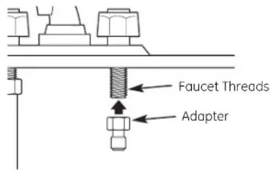
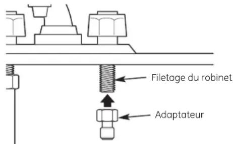
3 INSTALL FAUCET ADAPTER
Install the 3/8" x 1/2" faucet adapter to the faucet threads.
DO NOT OVERTIGHTEN.
Option A – Typical Installation
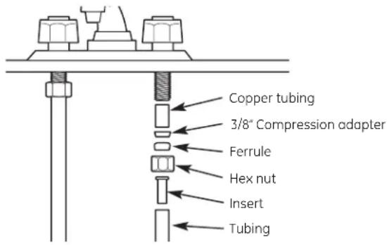
Option B - Optional Installation
If you have copper tubing with a compression adapter, you will NOT use the 1/2" faucet adapter.
Use a section of tubing, slide the compression hex nut and 3/8' ferrule (tapered end away from the compression nut) onto the tubing, and put in the tubing insert.
4 INSTALL THE HEAD/BRACKET
A Using the filter head/bracket as a guide, mark hole locations so that there is 1" between the center of each screw. Fasten the filter head/bracket to the wall with the Phillips screws provided with the unit.
NOTE: Predrill 1/8" holes for easier installation.
B Make sure to leave at least 2-1/2" from the bottom of the system to allow for easy replacement of the filter cartridge.
C Install screws only halfway so you can slip the bracket onto the wall during installation.
NOTE: There are three installation configurations. Select the appropriate screws for installation: For Cabinet Side Wall Installations, use 1" screws; For Drywall into Stud Installations, use 1-1/4" screws; For Drywall with No Stud Installations, use lag bolts.
CAUTION: Be sure screw point does not protrude through the wall into adjacent cabinet.
D Tighten screws to secure the bracket.
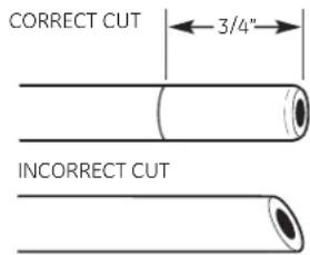
5 CUTTING THE TUBING
A Determine the length of tubing necessary from the filter head/bracket to the faucet and from the water supply line to the filter head/bracket by holding the tubing in place to ensure it is the correct length.
NOTE: 6 feet of tubing is supplied. Cut the tubing into two sections according to your requirements.
B Cut tubing.
NOTE: Do not kink tubing.
NOTE: Check the end of the tubing to make sure there are no cuts, nicks, flatpots or sharp edges. If any of these are present, cut the end of the tube with a utility knife.
C Measure 3/4" from the end of the tubing provided and mark with a pencil.
6 INSTALL TUBING
A Push the tubing firmly into the collet on the faucet adapter fitting until the pencil mark is pushed next to the collet. (If the tubing is removed, recut the end, measure, mark and reinsert.)
Tubing must be fully inserted to avoid leaks. To remove tubing: Depress and hold the white collet; pull the tubing out to remove.
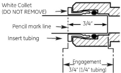
B Pull out slightly on the tubing to ensure a good seal
C Press the other end of the tubing into the outlet side of the filter.
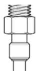
7 INSTALL COMPRESSION FITTINGS
A Take the remaining section of tubing, slide the compression hex nut and 3/8" ferrule (tapered end away from the compression nut) onto the tubing, and put in the tube insert
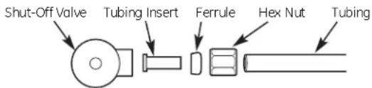
B Fasten the assembly onto the cold water supply valve. Do not overtighten.
NOTE: Overtightening will cause the tubing to separate from the fitting.
NOTE: For shut-off valves with 1/2" or 7/16" compression fittings, please use appropriate adapters provided in the kit.
C Connect the other end to the inlet side as indicated by the arrow on the filter head/bracket.
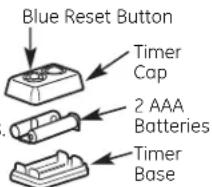
8 INSTALL THE BATTERIES
A Insert coin or screwdriver in the slot between the timer cap and base.
B Gently pry open and separate the timer base from the cap. Install or change 2 new AAA 1.5 volt batteries. After having the batteries in place, line up the base and cap and snap them back together.
C After new batteries are installed or appearance may vary. filter is changed, push and hold the timer blue reset button for approximately 5 seconds. Release the reset button after the light flashes 5 times. The light will flash again in 180 days to remind you that it is time to change the filter
D Attach timer to remote location for easy viewing.
NOTE: Timer
NOTE: Do not mix old and new batteries. Do not mix alkaline, standard (carbon-zinc) or rechargeable (ni-cad, ni-mh, etc.) batteries.
9 FINAL CHECK
A Insert the filter into the filter head/bracket. Turn the filter 1/4 turn to the right until it stops. The top surface of the filter will become flush with the bottom of the filter head/bracket when it is fully installed.
B Slowly turn on the water supply.
C Check the entire system for leaks. If there are leaks, refer back to the Cut the Tubing section to reinsert the tubing.
D If leaking from fittings, shut off water pressure and tighten orreseal fittings. If leaking from the filter, tighten the filter.
E After installation, let water run for approximately 5 minutes to flush the filter and to remove air.
NOTE: It is normal for there to be air in the system causing bubbles in the water.
PARTS LIST
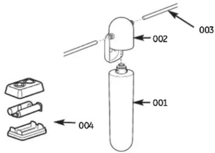
Ref. No. Part No. Part Description
001 GXULQR Replacement Filter Cartridge 1
002 WS19X10024 Filter Head/Bracket 1
003 GXULQ-KIT Kit 1 004 GXULQ-TIMER Timer and Batteries 1
To obtain replacement parts, call toll-free 800.626.2002 (U.S.),
800.663.6060 (Canada–English), 800.361.3869 (Canada–French).
GE Consumer & Industrial
Appliances
General Electric Company
Louisville, KY 40225
LIMITED ONE YEAR WARRANTY
• What does this warranty cover?
— Any defect in materials or workmanship in the manufactured product.
• What does this warranty not cover?
— Filter cartridge and batteries after 30 days from date of purchase.
— Service trips to your home to teach you how to use the product.
— Improper installation, delivery or maintenance.
— Failure of the product if it is abused, misused, altered, used commercially or used for other than the intended purpose.
— Use of this product where water is microbiologically unsafe or of unknown quality, without adequate disinfection before or after the system. Systems certified for cyst reduction may be used on disinfected water that may contain filterable cysts.
— Damage to the product caused by accident, fire, floods or acts of God.
- Incidental or consequential damage caused by possible defects with this appliance, its installation or repair.
• For how long after the original purchase?
- One (1) year.
• How do I make a warranty claim?
- Return to the retailer from which it was purchased, along with a copy of the "Proof of Purchase." A new or reconditioned unit will be provided. This warranty excludes the cost of shipping the product to your home.
EXCLUSION OF IMPLIED WARRANTIES—Your sole and exclusive remedy is product exchange as provided in this Limited Warranty. Any implied warranties, including the implied warranties of merchantability or fitness for a particular purpose, are limited to one year or the shortest period allowed by law.
This warranty is extended to the original purchaser and any succeeding owner for products purchased for home or office use within the USA. In Alaska, the warranty excludes the cost of shipping or service to your home or office.
Some states do not allow the exclusion or limitation of incidental or consequential damages. This warranty gives you specific legal rights, and you may also have other rights, which vary from state to state. To know what your legal rights are, consult your local or state consumer affairs office or your state's Attorney General.
4 Contact us at ge.com, or call toll-free at 800.952.5039 in the U.S., or 866.777.7627 in Canada.
Instructions d'Installation
Pression requise: 20–100 psi (1.4–6.9 bar)
Option A – Installation normale
General Electric Company
Louisville, KY 40225
GARANTIE LIMITÉE D'UN AN
natural_image
Line drawings of four different types of tools: screwdriver, flat blade, wrench, and drill bit (no text or labels)No. de ref. Parte No.
Descripción
General Electric Company
Louisville, KY 40225
GARANTÍA LIMITADA POR UN AÑO
- Installation Instructions
- Kitchen and Bath Main Faucet Filtration System – GXULQ/GNULQ
- SAFETY PRECAUTIONS
- PARTS INCLUDED
- TOOLS YOU WILL NEED
- PROPER INSTALLATION
- CARTRIDGE SPECIFICATIONS
- Performance Data - Filtration System GXULQ Using Filter GXULQR
- STEP-BY-STEINSTALLATION INSTRUCTIONS
- Installation Overview
- FILTER CARTRIDGE REPLACEMENT
- Replacement Filter Canister/Estimated Replacement Costs
- FILTER CARTRIDGE REPLACEMENT (cont.)
- TO REPLACE FILTER:
- INSTALLING THE SYSTEM
- SELECT A LOCATION
- DISCONNECT COLD WATER SUPPLY
- INSTALL FAUCET ADAPTER
- INSTALL THE HEAD/BRACKET
- CUTTING THE TUBING
- INSTALL TUBING
- INSTALL COMPRESSION FITTINGS
- INSTALL THE BATTERIES
- FINAL CHECK
- Ref. No. Part No. Part Description
- LIMITED ONE YEAR WARRANTY
- Instructions d'Installation
- GARANTIE LIMITÉE D'UN AN
- No. de ref. Parte No.
- Descripción
- GARANTÍA LIMITADA POR UN AÑO
Brand : GE
Model : GNULQ
Category : Water Filtration