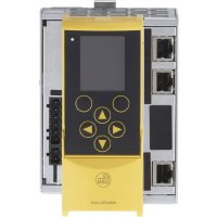
AC402S - Controller IFM - Free user manual and instructions
Find the device manual for free AC402S IFM in PDF.


User questions about AC402S IFM
0 question about this device. Answer the ones you know or ask your own.
Ask a new question about this device
Download the instructions for your Controller in PDF format for free! Find your manual AC402S - IFM and take your electronic device back in hand. On this page are published all the documents necessary for the use of your device. AC402S by IFM.
USER MANUAL AC402S IFM
Original operating instructions
Fail-safe SmartPLC SafeLine+ with PROFINET
interface
Firmware V6.1.8 or higher
AC402S
Contents
1 Preliminary note 3
1.1 Symbols used 3
1.2 Warnings.... 3
2 Safety instructions.... 4
3 Items supplied.... 5
3.1 Firmware.... 5
4 Intended use 6
4.1 Safety symbol on the device 6
4.2 IT safety 6
4.3 Safety-related requirements 6
5 Function description 7
6 Installation.... 8
6.1 Install device.... 8
7 Operating and display elements 9
7.1 LED indicators....9
7.1.1 Device LED H1 9
7.1.2 Interface LEDs on X6, X7 9
7.1.3 Interface LEDs on X8 10
8 Electrical connection.... 11
8.1 Wiring 11
8.2 Connecting the supply voltage 11
8.2.1 Standard configuration: 24 V power supply and AS-i power supply/supplies.....11
8.3 Connecting sensors / actuators.... 12
9 Operation 13
9.1 Electrical voltage supply 13
9.2 Ethernet interfaces X3 and X8 13
9.3 Fieldbus interfaces X6 and X7 13
9.4 AS-i interfaces.... 13
9.5 Local safe inputs and outputs X4 13
9.6 Notes on the EMC-compliant operation.... 14
9.7 Settings.... 14
9.7.1 Language selection.... 14
9.7.2 Navigation.... 15
9.7.2.1 Navigation elements 15
9.7.2.2 Pictograms and main navigation 15
9.7.2.3 OSC (Online Support Centre) 16
10 Technical data.... 17
11 Maintenance, repair and disposal 21
11.1 Replacing the buffer battery 21
1 Preliminary note
You will find instructions, technical data, approvals and further information using the QR code on the unit / packaging or at www.ifm.com.
1.1 Symbols used
√ Requirement
Instructions
Reaction, result
[...] Designation of keys, buttons or indications
→ Cross-reference

Important note
Non-compliance may result in malfunction or interference.

Information
Supplementary note
1.2 Warnings
Warnings indicate the possibility of personal injury and damage to property. This enables safe product handling. Warnings are graded as follows:

WARNING
Warning of serious personal injury
▷ If the warning is not observed, fatal and serious injuries are possible.

CAUTION
Warning of minor to moderate personal injury
▷ If the warning is not observed, minor to moderate injuries are possible.
ATTENTION
Warning of damage to property
▷ If the warning is not observed, damage to property is possible.
2 Safety instructions
- The unit described is a subcomponent for integration into a system.
- The system architect is responsible for the safety of the system.
-
The system architect undertakes to perform a risk assessment and to create documentation in accordance with legal and normative requirements to be provided to the operator and user of the system. This documentation must contain all necessary information and safety instructions for the operator, the user and, if applicable, for any service personnel authorised by the architect of the system.
-
Read this document before setting up the product and keep it during the entire service life.
- The product must be suitable for the corresponding applications and environmental conditions without any restrictions.
- Only use the product for its intended purpose (→ Intended use).
- If the operating instructions or the technical data are not adhered to, personal injury and/or damage to property may occur.
- The manufacturer assumes no liability or warranty for any consequences caused by tampering with the product or incorrect use by the operator.
- Installation, electrical connection, set-up, operation and maintenance of the product must be carried out by qualified personnel authorised by the machine operator.
- Protect units and cables against damage.
- Replace damaged units, otherwise the technical data and safety will be impaired.
- Observe applicable documents.
3 Items supplied
• 1 fail-safe SmartPLC SafeLine
• 3 Combicon connection terminals
• 1 original operating instructions
• 1 EU declaration of conformity
• Service address list with ifm contacts
If one of the above-mentioned components is missing or damaged, please contact one of the ifm branch offices.

Device manual and programming manual are not supplied. These are available at www.ifm.com.
3.1 Firmware
The device is supplied with firmware version V6.1.8 or higher.
4 Intended use
The device integrates two AS-i masters, a safe PLC, a non-safe PLC, a WEB server and a PROFINET slave interface with 2-port switch.
The device
• controls the exchange of data to the sensor/actuator level.
• can be used as a safe and a non-safe controller (PLC).
- communicates with the higher control level via PROFINET.
- visualises sensor/actuator data on the integrated WEB server.
- allows device configuration via the WEB server.
When operated correctly, the system can be used in applications up to performance level e, category 4, according to EN ISO 13849-1 or IEC 61508/SIL3 ( → notes Electrical connection).
Installation must be in accordance with EN 60204 and EN 62026-2. If an AS-i network is controlling a machine with potentially dangerous movements and EN 60204-1 applies, a special insulation monitoring device must also be installed.

Depending on the safety components used the complete safety system can also be classified for a lower control category.

In the control cabinet in an industrial environment (indoors) as a permanently installed device with supply from SELV/PELV according to the technical data ( → Technical data).
4.1 Safety symbol on the device

Observe instructions in chapter "Electrical connection".

Safety symbol on the device:
▶ Adhere to the operating instructions for the safe operation of the unit.
4.2 IT safety
By default, the device is not intended for direct connection to IT systems. If this application is required, the users have to implement it (e.g. by using their own additional components).
4.3 Safety-related requirements
It must be ensured that the safety requirements of the respective application correspond to the requirements stated in these instructions.
Observe the following requirements:
▶ Adhere to EN 14119 for interlocking devices associated with guards.
▶ Adhere to the specified operating conditions ( → Technical data). Use of the device in the vicinity of chemical and biological media is not permitted.
▶ In case of faults within the device which result in the defined safe state: Take measures to maintain the safe state when the complete control system continues to be operated.
5 Function description
All information contained in the description of the configuration software and the installation instructions of the device must be adhered to. These documents provide all the required instructions regarding installation, configuration, operation and maintenance of the safe AS-i control cabinet module.
Information on the parameterizable safety functions of the safe AS-i control cabinet module can be found in the chapter “Monitoring devices” of the configuration software manual.

The products described here are designed to be components of a safety-oriented machine or control system. A complete safety-related system normally includes sensors, evaluation units, signalling components and concepts for safe switch-off. It is the responsibility of each manufacturer of a machine or installation to ensure a correct functioning of the whole system. The manufacturer of the safe AS-i module, his subsidiaries and affiliates are not in a position to evaluate all of the characteristics of a given machine or product not designed by him.
The manufacturer accepts no liability for any recommendation that may be implied or stated herein.
The warranty contained in the contract of sale is the sole warranty. Any statements contained herein do not create new warranties or modify existing ones.
The complete description of the configuration software, the operating instructions of the AS-i safety monitor and the operating instructions of the safe AS-i control cabinet module must be taken into account.

Maintenance requirement
A minimum of one testing per year is compulsory by a demand on the safety function.
6 Installation
6.1 Install device
The device must only be installed, connected and put into operation by a qualified electrician as the safe function of the device and machinery is only guaranteed when installation is correctly carried out.
▶ The installation and connection must comply with the applicable national and international standards.
▶ Responsibility lies with the person installing the device.
▶ Fix the device onto a 35 mm raised rail.
▶ Vertical installation (upright).
▶ Adhere to a minimum distance of 30 mm between the ventilation holes (perforated sheet) and other parts.
▶ Maximum operating altitude: 2000 m above sea level
▶ The protection rating of the device is IP 20. The device must be installed in a control cabinet that is lockable with at least IP 54 protection.
▶ Lay the cables in a cable duct.
▶ Keep the installation space of the device free from electrically-conductive particles.
Ensure a condensation-free environment. Avoid excessive dust, vibration and shock. The air circulation through the vents must not be impeded. Installation in environments with ionising radiation is not permitted.
Avoid installation in direct vicinity of frequency inverters or other interfering sources.
7 Operating and display elements

1: Device LED H1 green / yellow / red
2: Softkeys
3: Navigation buttons
4: AS-i bus and FE connection X1
5: 24V device voltage supply X2
6: Connection for 24V Safe-IO voltage supply and local inputs/outputs X4
7: Front flap
8: Slot for SD card
9: Ethernet interface X3
10: Ethernet interface X8
11: PROFINET interface X7
12: PROFINET interface X6
7.1 LED indicators
7.1.1 Device LED H1
The LED on the front panel signals the state of the device and the connected systems.
| LED state | Description |
| Green LED on: | Device has been started. There is no warning message. There is no error message. |
| Yellow LED flashes slowly (0.5 Hz): | There is a warning message. There is no error message. |
| Red LED flashes quickly (2 Hz): | There is an error message. |
7.1.2 Interface LEDs on X6, X7
| LED state | Description |
| Green LED on: | • Physical connection OK |
| Yellow LED flashing: | • Reception of data |
7.1.3 Interface LEDs on X8
| LED state | Description |
| Yellow LED on: | • Physical connection OK |
| Green LED flashes: | • Reception of data |
8 Electrical connection
▶ The device must be connected by a qualified electrician.
▶ Disconnect the plant from the mains supply before installation.
▶ Observe the national and international regulations for the installation of electrical equipment.
▶ Connect the device as indicated on the terminals.
▶ Ensure an electrical connection between the device (X1, terminal FE) and the ground of the installation.
▶ Ground the X3, X6, X7 and X8 interfaces on both sides.
8.1 Wiring
| Terminal | Pin | Description |
| X1 | ||
| • AS-i 2 + | 1 | AS-i + for AS-i line 2 |
| • AS-i 2 - | 2 | AS-i - for AS-i line 2 |
| • AS-i 1 + | 3 | AS-i + for AS-i line 1 |
| • AS-i 1 - | 4 | AS-i - for AS-i line 1 |
| • FE | 5 | Functional earth |
| 6 | Not used | |
| X2 | ||
| • 24 V | 1 | +24 V device supply |
| • GND | 2 | GND |
| X4 | ||
| • IN1... IN8 | 1...8 | Input channels |
| • OUT1... OUT4 | 9...12 | Output channels |
| • GND | 13, 14 | Voltage ground safety IO PCB |
| • +24V | 15, 16 | +24 V supply voltage safety IO PCB |
8.2 Connecting the supply voltage
8.2.1 Standard configuration: 24 V power supply and AS-i power supply/supplies
▶ Connect the supply voltage inputs of the device to the power supply intended for this purpose.
- AS-i bus 1
- Connect the AS-i 1+ and AS-i 1- pins of terminal X1 to the AS-i power supply (e.g. AC1254) of the first AS-i bus.
- AS-i bus 2
- Connect the AS-i 2+ and AS-i 2- pins of terminal X1 to the AS-i power supply (e.g. AC1254) of the second AS-i bus.

Power must be applied simultaneously to the Safe-IO module (terminal X4) and to the device (terminal X2).
24V device supply:
Connect the pins 24 V and 0 V of terminal X2 to a 24 V DC power supply (18...32 V SELV/PELV).
24 V Safe-IO power supply:
Connect the pins 24 V and GND of terminal X4 to a 24 V DC power supply (18...32 V SELV/PELV).
▶ Ensure a low-resistance connection of the symmetry point of the device (terminal X1, pin 5 FE) to the ground of the installation.
▶ For the 24 V power supply (device, Safe-IO), select a power supply which supplies an output current of at least 3 A.
▶ The cable length of the DC supply between power supply and the device is to be limited to max. 3 m.
The power supplies used must meet the standard DIN EN 60950-1 for SELV/PELV.
8.3 Connecting sensors / actuators
The sensors or actuators are connected to the local (safe) inputs and outputs via terminal X4.
Valid combinations of the local input channels for the connection of 2-channel sensors:
- IN1 and IN8
- IN2 and IN7
- IN3 and IN6
- IN4 and IN5

WARNING
Invalid combination of the local inputs for the connection of 2-channel sensors
▷ Safety-related functions are ineffective
▷ Required SIL / cat. / PL is not achieved
▶ When connecting 2-channel sensors for the implementation of safety-related functions according to SIL3 / cat.4 / PL e, use a valid input combination.
▶ Connect the sensor switching signals to the pins IN1... IN8 of terminal X4.
▶ Connect actuators to the pins OUT1... OUT4 of terminal X4.
▶ When external sensors / actuators are connected, their supply voltage and/or reference potential of terminal X4 (Safe-IO module supply) must be tapped.
▶ When external sensors are connected, observe the max. permitted supply voltage of the sensor and select the Safe-IO module supply accordingly.
▶ The signal cable length for external devices (sensors, actuators) is to be limited to max. 10 m. The signal cables must not leave the building.
▶ Do not exceed the maximum output current of 0.5 A per output.
▶ Do not exceed a switching frequency of 25 Hz when connecting the inductive loads (DC-13).
9 Operation
9.1 Electrical voltage supply
Device supply from 24 V (AUX)
9.2 Ethernet interfaces X3 and X8
• RJ45, twisted pair (10 Mbps and 100 Mbps)
• TCP/IP - Transport Control Protocol / Internet Protocol
• UDP/IP - User Datagram Protocol
- EtherCAT (master) including FSoE (Fail Safe over EtherCAT)
• Modbus TCP (master / slave)
- Ethernet/IP (scanner)
• 3S fail-safe network-global variables
- HTTP server
• CODESYS programming interface
- OPC UA server
• CODESYS Web visualisation
9.3 Fieldbus interfaces X6 and X7
• PROFINET RT device class B (100 Mbps)
9.4 AS-i interfaces
- 2 AS-i master
• Ground-fault detection
9.5 Local safe inputs and outputs X4
In the following they are called Safe-IO.
• 8 connection terminals for
– up to 4 safe inputs according to SIL3 / PL e / category 4
– up to 8 non-safe inputs

Use safe inputs always with two channels.
• 4 connection terminals for
– up to 2 safe semiconductor outputs according to SIL3 / PL e / category 4
– up to 4 non-safe outputs
9.6 Notes on the EMC-compliant operation
- Use voltage supplies for the device that are not simultaneously used for the supply of known interfering sources (e.g. large inductive loads, motor starters, frequency converters, etc.).
- If the switching outputs of the device are used to control inductive loads (relays, contactors etc.), additional means of suppression have to be provided directly on those loads.
- Lay the cables of the digital inputs and outputs to be connected via the front connector in separated cable ducts. There should be no other cables in these ducts that are control or supply cables of known interfering sources.
Electromagnetic compatibility (EMC):
This is a class A product. This product may cause radio interference in domestic areas:
▶ If required, take appropriate EMC screening measures.
9.7 Settings
During operation the display is switched off after 10 minutes without operation.
▶ Activate the display by pressing any button.
9.7.1 Language selection

▶ Change the user language of the device by pressing the ▶ button and the ▲ button or ▼ button simultaneously.
9.7.2 Navigation
9.7.2.1 Navigation elements
1: Focus
2: Operating range
3: Softkey labelling (e.g. menu, OSC)
4: Navigation compass
5: Navigation status bar
6: Main navigation bar
7: Info bar
9.7.2.2 Pictograms and main navigation
| 1 ASi | AS-i 1 |
| • AS-i master settings• AS-i diagnostics• AS-i slaves |
| AS-i 2 | |
| • AS-i master settings• AS-i diagnostics• AS-i slaves |
| System | |
| PLC– Information– Settings– Diagnostics InformationSettings Diagnostics |
| Interfaces | |
| Settings and information of the Ethernet interface Settings and information of the Ether Net/IP interface |
| Safety | |
| • Settings, information and diagnostics of the safe controller |

Further details → device manual
9.7.2.3 OSC (Online Support Centre)
It is accessed via the softkey [OSC] on the start screen. In the process, events, warning and error messages with time stamp are displayed in plain text.
- Current
- History
10 Technical data
AC402S
AS-Interface PROFINET gateway with fail-safe PLC
SmartPLC SafeLine 2ASi PN


Application
| Design | housing for DIN rail mounting | |
| Application | PROFINET gateway with safe preprocessing | |
| Electrical data | ||
| Operating voltage | [V] | 18...32 DC; (AUX) |
| Current consumption | [mA] | < 750 |
| Max. current consumption from AS-i | [mA] | AS-i 1: 10 mA; AS-i 2: 10 mA |
| Number of AS-i masters | 2 | |
| Electrical separation | yes | |
| Inputs | ||
| Input circuit of digital inputs | PNP; (type 2 according to IEC 61131-2) | |
| Sensor supply of the inputs | to SELV/PELV | |
| Power supply | [V] | 24; (18...32 DC) |
| Input current High | [mA] | 7 |
| Outputs | ||
| Circuit | PNP | |
| Voltage range DC | [V] | 24; (18..32 DC ; to SELV/PELV) |
| Max. current load per output | [mA] | 500; (utilisation category DC-13 (control of electromagnets)) |
| Switching frequency AC | [Hz] | < 25 |
| Short-circuit proof | yes | |
AC402S
AS-Interface PROFINET gateway with fail-safe PLC
SmartPLC SafeLine 2ASi PN

| Electrically separated | yes |
| Interfaces | |
| Communication interface | Ethernet; OPC-UA |
| Ethernet - EtherCAT | |
| Protocol | EtherCAT |
| Usage type | data transmission; programming |
| Ethernet - Ether Net/IP | |
| Transmission rate | 100 MBaud |
| Protocol | Ether Net/IP |
| Usage type | programming |
| Ethernet - FSoE | |
| Protocol | FSoE |
| Ethernet - Modbus TCP | |
| Transmission rate | 10 MBaud; 100 MBaud |
| Connector type | RJ45 |
| Protocol | Modbus TCP |
| Usage type | programming |
| Ethernet - PROFINET | |
| Transmission rate | 100 MBaud |
| Connector type | RJ45 |
| Protocol | PROFINET |
| Usage type | data transmission |
| Note on interfaces | Device Class B |
| Ethernet - TCP/IP | |
| Transmission rate | 10 MBaud; 100 MBaud |
| Connector type | RJ45 |
| Protocol | TCP/IP |
| Usage type | programming |
| Ethernet - UDP/IP | |
| Transmission rate | 10 MBaud; 100 MBaud |
| Connector type | RJ45 |
| Protocol | UDP/IP |
| Usage type | programming |
| Operating conditions | |
| Ambient temperature [°C] | 0...45 |
| Note on ambient temperature | cULus: ...50 °C |
| Storage temperature [°C] | -20...70 |
| Max. relative air humidity [%] | 95; (non condensing) |
| Max. height above sea level [m] | 2000 |
| Protection | IP 20 |
| Safety classification | |
| Complies with the requirements | ISO 13849-1: 2023 category 4, PL e |
| IEC 61508 SIL 3 | |
AC402S
AS-Interface PROFINET gateway with fail-safe PLC
SmartPLC SafeLine 2ASi PN

| Mission time TM [h] | 175200 |
| Mission time TM (additional indication) | 20 years |
| PFH [1/h] | 1,21E-08 |
| PFD | 1,04E-04 |
| Max. internal inductance [μH] | 400 |
AS-i classification
| AS-i version | 3.0 |
| AS-i master profile | M4 |
| AS-i certificate | 125301 |
Mechanical data
| Weight [g] | 840.7 |
| Housing | rectangular |
| Type of mounting | mounting on DIN rail; (TH35 (EN 60715)) |
| Dimensions [mm] | 135.5 x 93 x 106.2 |
| Materials | aluminium powder-coated; steel sheet galvanised; PC |
Displays / operating elements
| Display | function | 1 x LED, red/green |
| full graphic LCD display |
Accessories
| Items supplied | terminals |
| Remarks | |
| Pack quantity | 1 pcs. |
AC402S
AS-Interface PROFINET gateway with fail-safe PLC
SmartPLC SafeLine 2ASi PN

Electrical connection - 1
Connection
X1, X2 Power supply

Electrical connection - 2
Connection
X4 Local inputs/outputs

11 Maintenance, repair and disposal
The operation of the unit is maintenance-free.
Only the manufacturer is allowed to repair the unit.
▶ After use dispose of the device in an environmentally friendly way in accordance with the applicable national regulations.
Cleaning the unit:
▶ Disconnect the unit from the voltage supply.
▶ Clean the unit from dirt using a soft, chemically untreated and dry micro-fibre cloth.
11.1 Replacing the buffer battery
Replace the buffer battery of the real-time clock as required, type CR2032.


- 1 PRELIMINARY NOTE
- 1.1 SYMBOLS USED
- 1.2 WARNINGS
- 2 SAFETY INSTRUCTIONS
- 3 ITEMS SUPPLIED
- 3.1 FIRMWARE
- 4 INTENDED USE
- 4.1 SAFETY SYMBOL ON THE DEVICE
- 4.2 IT SAFETY
- 4.3 SAFETY-RELATED REQUIREMENTS
- 5 FUNCTION DESCRIPTION
- 6 INSTALLATION
- 6.1 INSTALL DEVICE
- 7 OPERATING AND DISPLAY ELEMENTS
- 7.1 LED INDICATORS
- 7.1.1 DEVICE LED H1
- 7.1.2 INTERFACE LEDS ON X6, X7
- 7.1.3 INTERFACE LEDS ON X8
- 8 ELECTRICAL CONNECTION
- 8.1 WIRING
- 8.2 CONNECTING THE SUPPLY VOLTAGE
- 8.2.1 STANDARD CONFIGURATION: 24 V POWER SUPPLY AND AS-I POWER SUPPLY/SUPPLIES
- 8.3 CONNECTING SENSORS / ACTUATORS
- 9 OPERATION
- 9.1 ELECTRICAL VOLTAGE SUPPLY
- 9.2 ETHERNET INTERFACES X3 AND X8
- 9.3 FIELDBUS INTERFACES X6 AND X7
- 9.4 AS-I INTERFACES
- 9.5 LOCAL SAFE INPUTS AND OUTPUTS X4
- 9.6 NOTES ON THE EMC-COMPLIANT OPERATION
- 9.7 SETTINGS
- 9.7.1 LANGUAGE SELECTION
- 9.7.2 NAVIGATION
- 9.7.2.1 NAVIGATION ELEMENTS
- 9.7.2.2 PICTOGRAMS AND MAIN NAVIGATION
- 9.7.2.3 OSC (ONLINE SUPPORT CENTRE)
- 10 TECHNICAL DATA
- 11 MAINTENANCE, REPAIR AND DISPOSAL
- 11.1 REPLACING THE BUFFER BATTERY
Brand : IFM
Model : AC402S
Category : Controller