Domix 35 - Measuring equipment Doyon - Free user manual and instructions
Find the device manual for free Domix 35 Doyon in PDF.

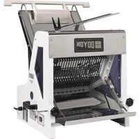
| Product type | Electronic water dispenser with thermostatic mixer |
| Brand | Doyon |
| Model | Domix 35 |
| Power supply | 208-240 V AC or 110-127 V AC, 50/60 Hz |
| Power consumption | 25 VA |
| Power fuse | T250 mA delayed @ 230 V, T630 mA delayed @ 115 V |
| Pump remote fuse | 250 V – 6.3 A |
| Protection rating | IP 42 |
| Installation category | II |
| Ambient temperature range | 5 °C to 50 °C (40 °F to 120 °F) |
| Relative humidity | 0% to 95% (non-condensing) |
| Water connections | 1/2" (threaded) |
| Max water pressure | 5 bar (72.5 psi) |
| Min water pressure | 1 bar (14.5 psi) |
| Max inlet water temperature | 65 °C (149 °F) |
| Temperature adjustment range | 2 °C to 60 °C (36 °F to 140 °F), precision ±1 °C |
| Water flow (at 1 bar, 20 °C) | 18 L/min (55 lb/min) |
| Water flow (at 5 bar, 20 °C) | 40 L/min (121 lb/min) |
| Maximum dispensing capacity | 999.9 L / 99 lb + 15 oz / 999.9 lb (depending on unit) |
| Dispensing accuracy | ±1% (min. discharge 5 L) |
| Internal probe | PT1000 Class A thermistor |
| Discharge hose | Ø 16 mm, food-grade plastic |
| Main functions | Accurate dispensing with memory, thermostatic mixing, manual stop, free discharge, self-diagnosis |
| Maintenance and cleaning | Clean the external filter regularly, clean the exterior with a soft sponge and mild soap, do not direct water jets, clean the internal diaphragm of the solenoid valve every 6 months |
| Safety | Prohibited for use by children or unassisted disabled persons, disconnect before cleaning or opening, mandatory grounding |
| Spare parts and repairability | Original spare parts available (ball valve, filter, flow meter, probe, solenoid valve, mixer, etc.); repair by manufacturer or authorized distributor |
| General information | 1-year warranty, installation by qualified personnel, recycling according to WEEE |
Frequently Asked Questions - Domix 35 Doyon
User questions about Domix 35 Doyon
0 question about this device. Answer the ones you know or ask your own.
Ask a new question about this device
Download the instructions for your Measuring equipment in PDF format for free! Find your manual Domix 35 - Doyon and take your electronic device back in hand. On this page are published all the documents necessary for the use of your device. Domix 35 by Doyon.
USER MANUAL Domix 35 Doyon
natural_image
Pure electrical circuit lines without any symbolsFIG. 4

natural_image
Pure electrical circuit lines without any symbolsFIG. 5
natural_image
Pure electrical circuit lines without any symbolsFIG. 6
Fig. 2 (Layout collegamentl idraulici; Layout hydraulic connections; connexions hydrauliques)
Manual Code 2600103
flowchart
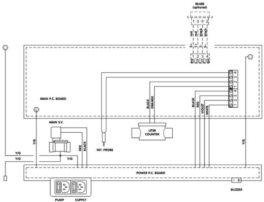
Electrical wiring diagram showing connections between main P.C. board, power P.C. board, and buzzer with labeled components like LITER COUNTER and black/red lines.text_image
[6,65] 169Manual Code 2600103
natural_image
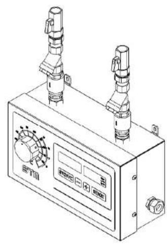
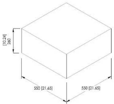
Technical line drawing of a mechanical device with two vertical ports and a control panel (no text or symbols visible)Fig. 4 (Dimensioni; Dimensions; Dimensions)
text_image
[10.24] 260 550 [21.65] 550 [21.65]INDICE / INDEX
1- TECHNICAL FEATURES....9
1.1. DESCRIPTION 9
2- MANUAL INTERPRETATION .... 10
3- PRELIMINARY INSPECTION 10
4- BASIC RULES OF SAFETY 10
5- MANUFACTURER DECLARATION .... 11
5.1. WARRANTY 11
5.2. UNPACKING 11
5.3.STORAGE 11
6- INSTALLATION 12
| Power supply (see machine rating plate) 208-24 | 0V AC or 110-127V AC |
| Mains frequency 50/60 Hz | |
| Total absorbed power 25 VA | |
| Installation category II | |
| Environmental conditions Indoor use only | Temperature range 5 ÷ 50^ ( 40 ÷ 120^ )Relative humidity range 0 ÷ 95% |
| Hydraulic inlet connections 1/2" | |
| Hydraulic outlet connections 16 mm diameter | |
| Maximum temperature at inlet 65^ ( 149^ ) | |
| Operating regulation range | 2 ÷ 60^ ( 36 ÷ 140^ ) precision +/- 1^ |
| Maximum inlet pressure 5 bar (72,5 psi) | |
| Minimum inlet pressure 1 bar (14,5 psi) | |
| Max ratio between the two entry pressures 1 : 5 | |
| Maximum batch 999,9 L; 99 lb + 15 oz; 999,9 lb | |
| Dosing precision | ± 1% (min batch: 5 L) |
| Flow rate at 1 bar and 20^ 18 L/min (40 lb/min) | |
| Flow rate at 5 bar and 20^ 40 L/min (88 lb/min) | |
| Internal probe | Thermo-resistor PT1000 typeA |
| Supply fuse | 250 V – T250 mA retarded @ 208-240 V250 V – T630 mA retarded @ 110-127 V |
| Pump control fuse | 250 V – F6,3 A |
| Protection Rating | IP 42 |
1.1. DESCRIPTION
(See Fig. 1)
- Ball-taps with OR gasket.
- OR gasket-type unions for an easier installation.
- Stainless steel double mesh filters for water impurities.
- No-return valves.
- Regulation knob for temperature setting, with reference scale.
- [STOP/C] key, for manual stopping or memory resetting.
- [+] and [-] keys for setting the quantity.
- [START] key, for starting or resuming a delivery.
- Supply plug, with fuse and spare, and remote pump control plug, with fuse and spare.
- 2,5 m delivery hose with stainless steel terminals.
- Series of function control lights.
- Digital display of electronic internal thermometer, showing ^ C with tenths or ^ F.
- Digital display showing the water quantity selected, still to be delivered (during the dosing), or already delivered (after pressing [STOP/C]).
2- MANUAL INTERPRETATION
All parts of the text that are important to the safety of people and objects are written in bold. The purpose of this manual is to provide the user, the installer and the maintenance technician with all the technical information required for the installation, use and ordinary maintenance operations to guarantee a long machine life.
Should any spare parts be required, only original components should be used. Requests for SPARE PARTS or INFORMATION relating to the unit must be made to the distributor or the nearest technical assistance centre, quoting the MODEL and MACHINE SERIAL NUMBER shown on the technical characteristics label.
The meaning of this symbol (used both on the machine and in this manual) is: Danger, electric shock risk.

The meaning of this symbol (used both on the machine and in this manual) is: Caution, please refer to attached documentation.

The meaning of this symbol (used both on the machine and in this manual) is: Operation prohibited.
3- PRELIMINARY INSPECTION
Inspect the unit as soon as it has been received.
Carefully check that all the components are on the packing list or invoice.
Promptly advise of any damage caused during transportation and send a claim to the courier without delay.
VERY IMPORTANT: the manufacturer shall not be held liable for whatever damage to the unit during transportation.
4- BASIC RULES OF SAFETY
The use of the device is prohibited for children and persons with disabilities who are not assisted.
It is prohibited to touch the device if you are barefoot and with body parts wet or damp.
Any cleaning operation is prohibited before it has disconnected the unit from the mains.
Not modify the safety devices or setting without the manufacturer permission.
It is prohibited detach, twist the wires even if it is disconnected from the mains.
It is prohibited to open it without having previously disconnected from the mains.
It is prohibited to disperse and leave to the reach of children the packaging. It can be potentially dangerous.
5- MANUFACTURER DECLARATION
THE MANUFACTURER DECLINES ANY LIABILITY WHATEVER FROM ANY DAMAGE DERIVING FROM IMPROPER USE OF THE MACHINE AND/OR USE OF THE MACHINE IN ENVIRONMENTAL CONDITIONS THAT ARE NOT ADMITTED.
5.1. WARRANTY
The manufacturer, through its authorised distributors, warrants the repair or free replacement of any part of this product that happens to break down due to defective material or workmanship within one year from delivery thereof, but not from improper or incorrect use, in compliance with the conditions outlined here below.
Materials that are subject to normal wear and tear such as pipes and tubing are excluded from this warranty. Any faulty products must be returned to the manufacturer, or to an authorised distributor at the customer's expense following agreement for the goods to be collected by courier. Any repairs or modifications must be carried out solely by the manufacturer or its authorised distributors or following explicit authorisation by the manufacturer or its authorised distributors. Any products that have been subjected to improper or incorrect use or have been purposely or accidentally damaged or overloaded are excluded from this warranty. The manufacturer shall not be held responsible for any warranty whatever given by anyone, including its distributors, in the name and on behalf of the manufacturer that does not fall within the terms outlined in this warranty clause, unless otherwise specifically approved in writing by the manufacturer.
5.2. UNPACKING
Unpack all parts with care and check the presence and good condition of all components.
Store the packaging so that it can be used to return the component, if necessary.
At the end of the equipment's life, dispose of the packaging material in compliance with local regulations. Pay particular attention to the expanded polystyrene protections. The outer box is in corrugated cardboard and can be recycled.
5.3. STORAGE
This product has a long shelf-life. Nevertheless, after storage care must still be taken to make sure that all parts function correctly.
6- INSTALLATION

Fundamental operations relating to lifting, transportation, installation, start-up, maintenance and repair work must be carried out only by qualified personnel.

Disconnect the electrical power supply when carrying out any of the above.
2 fuses, for the pump and logic board, are also fitted on the logic board and can also be replaced when needed only by qualified personnel.
The installation must be carried out by skilled personnel under the supervision of a qualified person. All electrical connections must comply with the local requirements at the place of installation. The machine must be earthed and protected against short circuits and overloads.
In case of hard water (with high lime scale content = hardness in French degrees higher than 25 ÷ 30 , or 250 ÷ 300 ppm) it is necessary to employ an ion exchange water softener. This unit must be calibrated so as to maintain a residual hardness ranging between 5 and 10 French degrees ( 50 ÷ 100 ppm). The use of electronic water softeners is not advised, since their efficacy has not been proved yet.
Fix the doser-mixer to the wall at 1350 ÷ 1550 mm height from the floor, using the two wall plugs supplied. The 90^ wall plug hook is supplied to provide support for the water delivery outlet elbow.

Do not place other machines below the device.
Arrange the water inlet tubings, mounting the ball taps (1) at their ends.
Provide to insulate thermically the inlet pipes to obtain the best performances.
It is recommended to perform links as short as possible from the chiller / boiler to the DOMIX, avoiding going through the pipes near sources of heat such as the ovens.
Perform a purge of all pipes to eliminate waste processing, which could damage the equipment.
Connect the doser to the ball taps using connectors (2).
Connect the delivery tube (10) to the machine.

Check that the voltage and frequency correspond to those shown on the unit data tag. Make sure that the electrical installation complies with the local electrical connections and safety regulations.
Connect to the proper power supply using the supplied flying socket, fitted with a three core cable min. section 3x1,5mm ^2 . An external switch is helpful.
For the eventual pump remote control, use the supplied flying socket to connect the remote control switch of the pump(s). The use of such a pump is necessary when one of the two inlet pressures in less than 1 bar, for example when using unpressurized water heaters or refrigerators.
NOTICE: in the case of water chiller equipped with a surge tank with pressure switch, this must be by-passed and the pump must be controlled directly by the Domix, through a power relay.
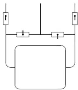
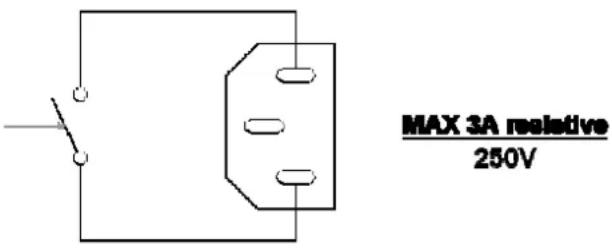
The pump command plug on the device has the following wiring diagram (clean contact, digital output, no tension output):
text_image
MAX 3A resistive 250VFig. 5 (pump control wiring diagram)
This is a normally open (NO) clean contact that closes when the unit requires chilled water. So it doesn't supply any tension.
It is recommended to use it to cut phases with current not higher than the amperage indicated in the figure.

7- UNIT OPERATION
Switch on the doser-mixer using the external switch (or by plugging in the flying socket). The first displays appearing at the switching on refer to the self-test. The displays show the model and the microprocessor software version.
At the end of the self-test the display show:
– The quantity of the last discharge.
- Internal temperature.
Set desired water quantity using [+] and [-] keys. Setting appears on display (13). Increases/decreases may be obtained in three different ways:
step by step: pressing once [+] and [-] keys
continuous: keeping constant pressure on [+] and [-] keys
fast: 3 seconds after keeping constant pressure on [+] and [-] keys.
Press [START] key to execute the batch.
Water delivery may be stopped at any time by pressing [STOP/C] key. Quantity of water delivered will then flash on display (13).
To resume delivery of remaining water press [START] key.
Press [STOP/C] key and the original litre setting will reappears on display. Press [STOP/C] key again to clear memory.
Quantity in memory is retained at the end of each dosing. Simply press [START] key if identical successive dosing is desired. Memory is protected against power failure; pre-set dosing can be resumed pressing [START] key when power is restored. In this case the display shows the message "TensFAI". At the first pressure of the [STOP/C] key the machine shows the discharged quantity till it was stopped, the operator may now cancel the discharge by pressing again the [STOP/C] key, or to resume by pressing [START].
Water temperature is selected by turning the temperature regulation knob: the temperature is shown on the electronic thermometer display. When regulating the water temperature wait a few seconds between adjustments so as to allow the temperature to stabilize.
To ensure optimum operation the warm water temperature must be at least 10^ C higher than the required delivery water temperature and the cold water should be at least 5^ C lower.
ATTENTION: the graduated scales are indicative. They suffer from the temperature of the water input. The scale "red" indicates the temperature of the mixed output when you use NETWORK+HOT. The scale "blue" indicates the temperature of the mixed output when you use CHILLED+NETWORK.
Low temperatures (below 10 ÷ 15^ ) may be obtained only when using a refrigerator.
The scales have been obtained with temperatures of 3^ C (refrigerated), 18^ C (net) and 65^ C (warm).
7.1. Free batch special function
It is possible to perform a special recipe controlling only the temperature (press [STOP] and [-] together to enter).
On the left display appears [FrEE], the right display shows the water temperature.
With the [START] and [STOP/C] keys the solenoid-valve opens and closes.
To exit, press [STOP] and [-] together.
This function may be useful also in case of a liter-counter failure.

8- ERRORS
All error messages are shown by flashing messages and an intermittent led signalling in the litres display. The last one can be stopped with the [STOP/C] key. Using the [START] key the error message is cancelled and the delivery starts again. On the contrary, the double [STOP/C] command cancels the delivery. The possible error messages are listed here below.
8.1. Litres-counter error
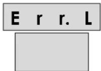
DISPLAY 1
If no pulses come from the litre counter, after 15" the message "Err.L" appears on the display. The message is cancellable with the [STOP/C] key and the machine turns into a temporary state where on the upper display is shown the delivered quantity. By pressing the [START] key the delivery continues, by pressing the [STOP/C] the machine turns into idle state.
For relative troubleshooting see paragraph 12-.
8.2. Probe Error
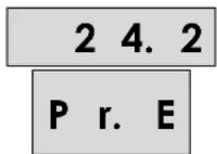
DISPLAY 2
The "Pr.E" message appears on the display referred to the damaged or wrongly connected probe. The machine is not blocked and it's possible to be operated. For relative troubleshooting see paragraph 12-.
8.3. Power Fail
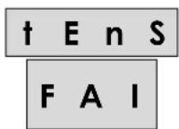
DISPLAY 3
If there is a tension fall during a water delivery, at the following switch-on the message “†EnS FAI” appears on the display. The message is cancellable with the [STOP/C] key and the machine turns into a temporary state where on the upper display is shown the delivered quantity. By pressing the [START] key the delivery continues, by pressing the [STOP/C] the machine turns into idle state.
8.4. Solenoid valve leaking
LEAK
E. V.
DISPLAY 4
It could happen that the solenoid valve doesn't close properly with some water leaking. In this case the following message appears: "LEAk E.V." This kind of error doesn't lock the device. The user can operate the machine, but if the problem is not solved the alarm will appear again.
To cancel the alarm the [STOP/C] key must be pressed.
For relative troubleshooting see paragraph 12-.
In the installer parameters it is also possible to deactivate the control.
9- MAINTENANCE INSTRUCTIONS
- Perform periodic cleaning of the external filters (3). The frequency depends on the impurities present in the pipes.
- To clean the external surface of the doser-mixer, use a soft sponge and water or a neutral detergent; for more resistant grime, use alcohol or turpentine.
- No direct jets of water on the device.
- When switching off the doser-mixer, set always the temperature regulation knob (5) to its mid position, to allow a minimum number of moves in the mixer valve, particularly when deliveries at the same temperature are carried out.
- Clean the internal membrane of solenoid valve regularly (6 months), particularly if the water contains a high quantity of lime-scale.
- Check periodically the litre-counter error, using a high precision scale.

The use of non-original spare parts is strictly prohibited.
The code for the spare parts are located in the Tab. 1
10- USELESS DEVICE DISPOSAL
The used package may be disposed through regular disposal treatment centres. It is made only of non polluting materials, recyclable as secondary prime materials. The device, accessories and batteries included, does not belong to the domestic disposals category, due it's made of valued materials which could be recycled and reused. The European Directory 2002/96/CE about electric and electronic devices disposal (RAEE) prescribes the separate collection of the electric and electronic devices respect to the mixed urban disposals for their further recovery, reuse and recycle. Don't dispose the electric and electronic devices together with domestic disposals or through the regular disposals collection services. The EU countries require the use of separate collection services. Be informed about your local separate collection services for electric and electronic devices disposal showing this symbol:
natural_image
Symbol of a trash bin crossed with a diagonal line, no text or numbers present11- CERTIFICATIONS

12- TROUBLESHOOTING
| PROBLEM CAUSE SOLUTION | ||
| The unit doesn't switch on | The power fuse in the logic board is burnt. | Disconnect the power and replace the fuse. |
| "Err.L" Internal terminal block or wires disconnected. | Disconnect the power, open the box and check the connections. | |
| "Liter-counter damaged. Replace the liter-counter. | ||
| "Pr.E" in the temperature display. | Internal terminal block or wires disconnected. | Disconnect the power, open the box and check the connections. |
| Temperature probe broken. Disconnect the power and replace the temperature probe. | ||
| "LEAk E.V." EV leaking. Discharge the pressure on the hydraulic circuit. Disconnect the power, and clean the EV. | ||
| "Serr.Err." (only if the optional serial port is present) | Communication port error. Check the power wires. Switch off and then on the machine. | |
1- CARACTERISTIQUES TECHNIQUES
text_image
MAX 3A resistive 250Vnatural_image
Symbol of a trash bin crossed with a diagonal line and a horizontal bar below (no text or labels)11- CERTIFICATIONS
CE
12- DEFAULTS DE FONCTIONNEMENT ET SOLUTIONS