VT8601 - Mirror V-TAC - Free user manual and instructions
Find the device manual for free VT8601 V-TAC in PDF.
| Brand | V-TAC |
| Model | VT8601 |
| Product type | LED wall mirror with integrated demister |
| Usage | Indoor only, bathroom (zone 2) |
| Power supply | 240V ~ 50Hz |
| Protection rating | IP44 |
| Installation zone | Zone 2 and outdoor areas (excluding zones 0 and 1) |
| Main functions | LED lighting, demister, ON/OFF switch (normal switch) |
| Control | Normal switch (non-touch for this model) |
| Color temperature | Not adjustable (fixed white) |
| Material | Glass frame and back housing |
| Wiring | 3 conductors (L, N, Earth) |
| Installation | By certified electrician, drilling for cable passage and wall mounting |
| Maintenance | Wipe with a soft cloth, do not use solvents |
| Warranty | 2 years (from date of purchase) |
| Repairability | Spare parts not specified; warranty does not cover damage from incorrect installation |
| Safety | Disconnect power before servicing, do not modify the product |
Frequently Asked Questions - VT8601 V-TAC
User questions about VT8601 V-TAC
0 question about this device. Answer the ones you know or ask your own.
Ask a new question about this device
Download the instructions for your Mirror in PDF format for free! Find your manual VT8601 - V-TAC and take your electronic device back in hand. On this page are published all the documents necessary for the use of your device. VT8601 by V-TAC.
USER MANUAL VT8601 V-TAC
WEEE Number: 80133970
INSTALLATION INSTRUCTION MIRROR LIGHTS
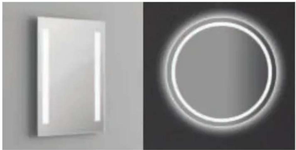
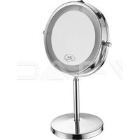
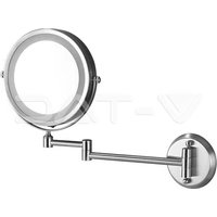
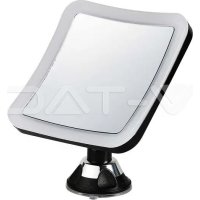
natural_image
Two minimalist wall-mounted screens: one with a white rectangular panel and the other with a glowing circular light source (no text or symbols)2 YEARS WARRANTY*
TECHNICAL DATA:

Anti-fog
| MODEL | WATTS | LUMENS | BEAM ANGLE | CRI | VOLTAGE/FREQUENCY | UNIT SIZE | IP RATING | DEMISTER PAD | BODY TYPE |
| VT-8505 | 17W | 600LM | 120° | >80 | AC:200–240V, 50/60Hz | H500xW390xD35mm | IP44 | 330×160mm | Iron |
| VT-8700 | 30W | 750LM | 120° | >80 | AC:200–240V, 50/60Hz | H700xW500xD35mm | IP44 | 450×250mm | Iron |
| VT-8701 | 25W | 750LM | 120° | >80 | AC:200–240V, 50/60Hz | H700xW500xD35mm | IP44 | 450×250mm | Iron |
| VT-8800 | 38W | 700LM | 120° | >80 | AC:200–240V, 50/60Hz | H800xW600xD35mm | IP44 | 560×330mm | Iron |
| VT-8601 | 25W | 750LM | 120° | >80 | AC:200–240V, 50/60Hz | øD:600xD35mm | IP44 | Dia360mm | Iron |
| VT-8602 | 25W | 750LM | 120° | >83 | AC:220–240V, 50Hz | øD:600xD35mm | IP44 | Dia360mm | Iron |
WARNING!
- Please make sure to turn off the power before starting the installation.
- Proper grounding should be ensured throughout the installation.
- The light source of this luminaire is not replaceable, when the light source reaches its end of life the whole luminaire should be replaced.
- Installation should only be done by a certified electrician.

This marking indicates that this product should not be disposed of with other household wastes.
Caution, risk of electric shock.
(FR) INTRODUCTION & GARANTIE
(PL) WSTĘP I GWARANCJAD
(RO) INTRODUCERE, GARANTIA
Thank you for selecting and buying V-TAC product. V-TAC will serve you the best. Please read these instructions carefully before starting the installation and keep this manual handy for future reference. If you have any another query, please contact our dealer or local vendor from whom you have purchased the product. They are trained and ready to serve you at the best. The warranty is valid for 2 years from the date of purchase. The warranty does not apply to damage caused by incorrect installation or abnormal wear and tear. The company gives no warranty against damage to any surface due to incorrect removal and installation of the product. The products are suitable for 10-12 Hours Daily operation. Usage of product for 24 Hours a day would void the warranty. This product is warranted for manufacturing defects only.

Multi-Language Manual QR CODE
Please scan the QR code to access the manual in multiple languages.
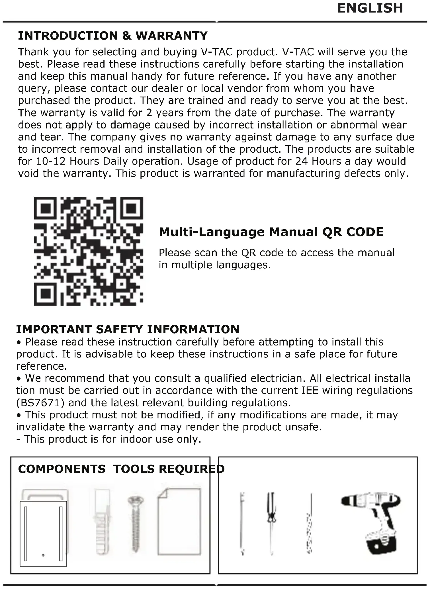
IMPORTANT SAFETY INFORMATION
- Please read these instruction carefully before attempting to install this product. It is advisable to keep these instructions in a safe place for future reference.
- We recommend that you consult a qualified electrician. All electrical installation must be carried out in accordance with the current IEE wiring regulations (BS7671) and the latest relevant building regulations.
- This product must not be modified, if any modifications are made, it may invalidate the warranty and may render the product unsafe.
- This product is for indoor use only.

natural_image
Illustration of four different types of electrical probes: a straight rod, a cylindrical component with a handle, a variable resistor, and a handheld device (no text or symbols present)SAFETY INSTRUCTIONS
- Installation should only be done by a certified electrician.
- Before commencing installation or maintenance, isolate the main electrical supply for appropriate circuit at the fuse board.
- This product is only suitable for connecting to a 240V 50Hz supply.
- The mirror light should be mounted onto a secure surface.
- When installing, please take care to avoid water pipes, joints, and electrical cables.
- This product has a rating of IP44.
- Do not exceed or stretch cables.
PRODUCT OVERVIEW
- This illuminated LED mirror is a sleek addition to any bathroom, providing beautiful lighting.
- The mirror light features stylish soft-edge corners, as well as an illuminated front face, which is perfect for everyday tasks.
- The mirror light is built-in with demister pad which guarantees that the mirror light will always stay perfectly clear.
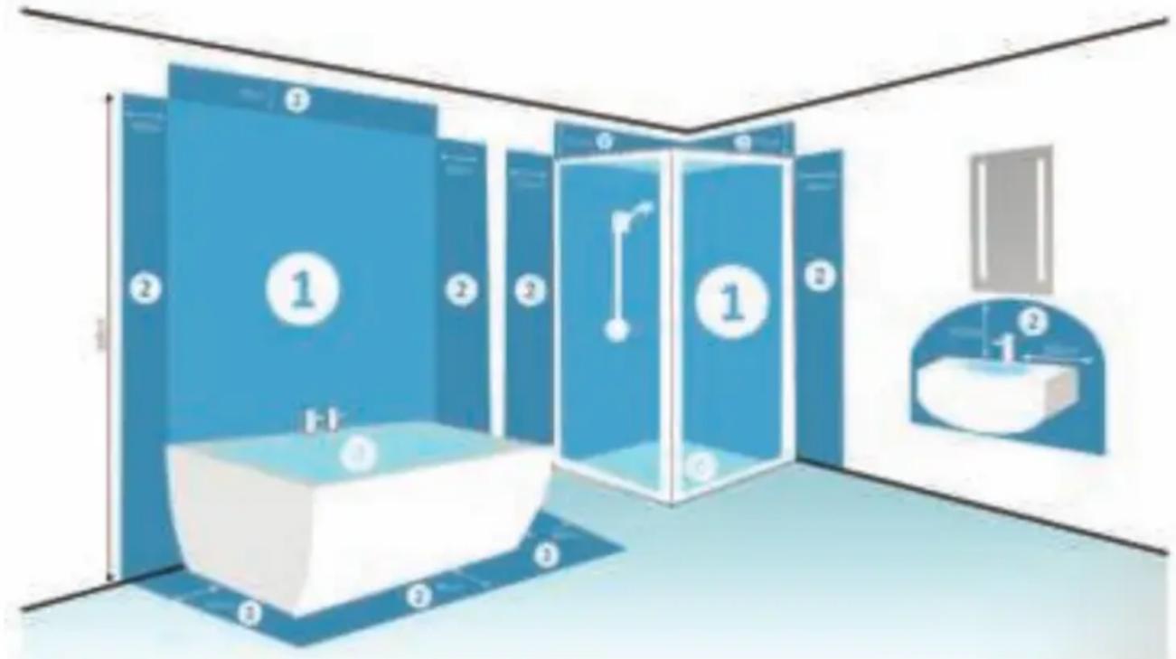
TYPES OF BATHROOM LIGHTING ZONES:
0 - Inside the bath or shower. Must be SELV (12V Max) due to water submersion. Minimum rating of IP67.
1 - 225cm above the bath or shower. Minimum rating of IP44.
2 - The area stretching to 60cm outside the bath or shower, and 60cm from the water outlet of the sink. An IP Rating of at least IP44 is required.
Outside Zones - Anywhere outside zones 0, 1 and 2, where water jets are not used for cleaning purposes, the general rules of BS7671 apply.
NOTE: V-TAC Mirror Lights are IP44 rated and suitable for installation in zone 2 and the outside zones ONLY.
INSTALLATION INSTRUCTIONS
natural_image
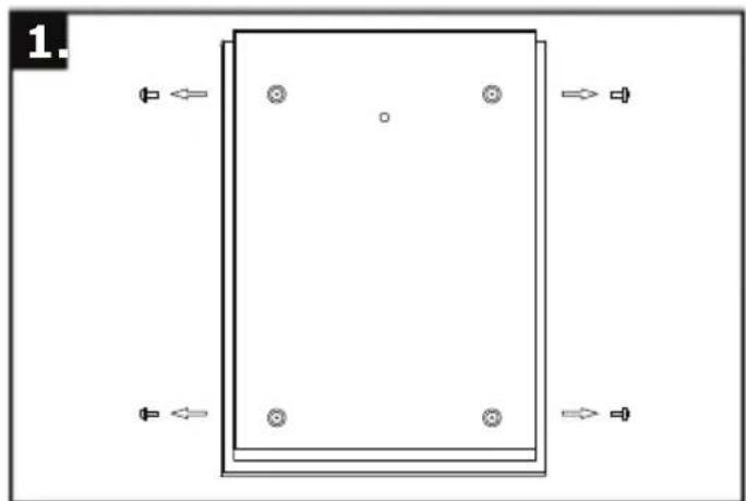
Pure diagram of a rectangular frame with four circular holes and directional arrows, no text or symbols present.Step 1: Lay the mirror face down and remove the screws with a Philips head screw driver.
Note: Be careful to lay the mirror on a padded surface, that will not cause any scratches or abrasions.
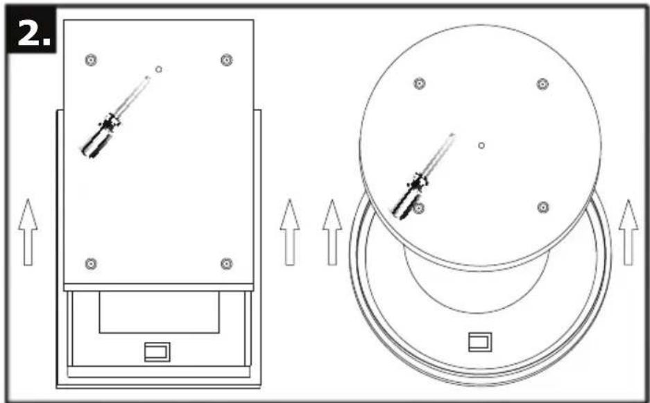
Step 2: Carefully separate the back box from the glass mirror and pierce the rubber grommet.
Note: The rubber grommet will isolate and trap any steam to ensure the mirror remains protected.
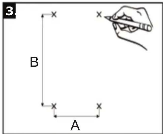
| ITEM NO | A(mm) | B(mm) |
| VT-8505 | 200 300 | |
| VT-8700VT-8701 | 300 500 | |
| VT-8800 | 400 600 | |
| VT-8601VT-8602 | 268 268 |
Note: Be careful before drilling to avoid any wiring or water pipes.
Step 3: Carefully mark your desired position for the mirror using the dimensions shown above. Then proceed to drill the holes for the Rawl plugs and screws.
natural_image
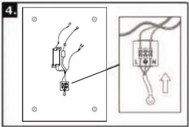
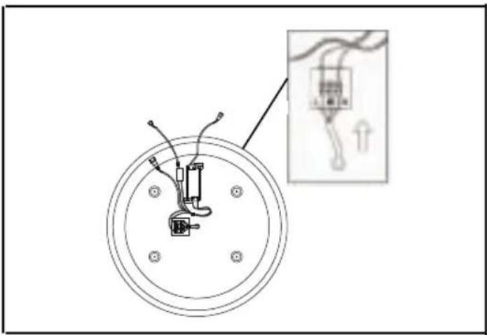
Diagram of a circular electrical component with wires and a magnified inset showing internal wiring (no text or symbols)Step 4: Thread a 3-core mains cable through the rubber grommet in the back box and connect it to the junction box.
Note: Please refer to the wiring diagram as shown below.
WIRING DIAGRAM
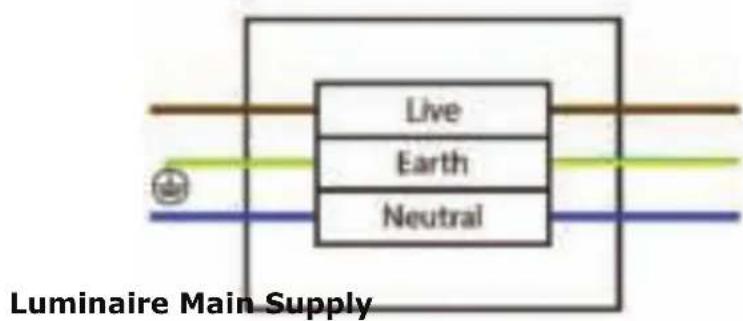
Live Supply can be Red or Brown. Earth Supply is Green and Yellow. Neutral Supply can be Blue or Black.
natural_image
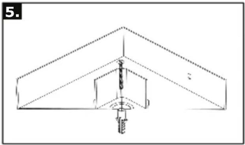
Pure technical line drawing of a structural support system without any text, numbers, or symbolsStep 5: Insert the Rawl plugs into the pre-drilled holes and then secure the back box to the wall using the four screws provided.
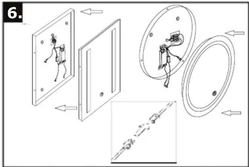
Step 6: Connect the male and felmale connectors for the demister pad and LED, proceed to slot the glass panel over the back box. Finally, re-insert the screw to fasten the two parts together.
TOUCH SWITCH AND CCT CHANGING OPERATIONS: (Applicable only for Model No.VT-8701 & VT-8602)
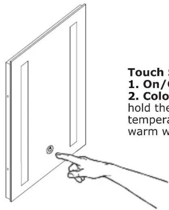
Touch Sensor
- On/Off - Touch to turn the light ON/OFF
- Colour Temperature - Press and hold the bottom to change the colour temperature between cool white and warm white.
Note: The touch switch and CCT changing operation is only designed for VT-8701 and VT-8602. The other models [VT-8505, VT-8700, VT-8800, VT-8601] work with a normal switch.
MAINTENANCE & CAREFULLY
- Ensure that the power is disconnected prior to cleaning.
- To keep the finish of this product, wipe out with soft cloth periodically.
- Do not use harsh chemical solvents, this may dis-colour or damage the finish.
- Do not over-tighten screw on the terminal block