DN170111 - Uninterruptible power supply Digitus - Free user manual and instructions
Find the device manual for free DN170111 Digitus in PDF.
User questions about DN170111 Digitus
0 question about this device. Answer the ones you know or ask your own.
Ask a new question about this device
Download the instructions for your Uninterruptible power supply in PDF format for free! Find your manual DN170111 - Digitus and take your electronic device back in hand. On this page are published all the documents necessary for the use of your device. DN170111 by Digitus.
USER MANUAL DN170111 Digitus
DIGITUS® All in One UPS system
natural_image
Exterior view of a black rectangular electronic device with ventilation slots and ports (no visible text or symbols)User Manual
DN-170110 • DN-170111
Safety Warning
-
The UPS utilizes voltages that may be hazardous. Do not attempt to disassemble the unit. The unit contains no user serviceable parts. Only factory service personnel may perform repairs.
-
Internal battery voltage is 12Vdc. sealed, lead-acid, 6 cells battery.
-
Connection to any other type of receptacle other than a two-pole, three-wire grounded receptacle may result in shock hazard as well as violating to local electrical codes.
-
In the event of an emergency, press the OFF button and disconnect the power cord from the AC power supply to properly disable the UPS.
-
Do not allow liquids or any external objects to enter the UPS. Do not place beverages or any other liquid-containing vessels on or near the unit.
-
This unit is designed for installation in a controlled environment (temperature controlled, indoor are free of conductive contaminants). Avoid installing the UPS in locations where there is static or flowing water, or excessive humidity.
-
Do not plug the UPS input into its own output.
-
Do not attach a power strip or surge suppressor to the UPS.
-
Do not connect non-computer-related items, such as medical equipment, life-support equipment, microwave ovens, or vacuum cleaners to UPS.
-
To reduce the risk of overheating the UPS, do not cover the UPS cooling vents and avoid exposing the unit to direct sunlight or installing the unit near heat emitting appliance such as air heaters or furnaces.
-
Unplug the UPS prior to cleaning and do not use liquid or spray detergent.
-
Do not dispose the batteries into fire as they may explode.
-
Do not open or mutilate the battery or batteries. Released electrolyte is harmful to the skin and eyes. It may be toxic.
-
A battery can present a risk of electrical shock and high short circuit current. The following precautions should be observed when working on batteries:
-
Remove watches, rings, or other metal objects from the hands.
- Use tools with insulted handles.
- Wear rubber gloves and boots.
- Do not lay tools or metal parts on the top of batteries.
-
Disconnect charging source prior to connecting or disconnecting batteries terminals.
-
Servicing of batteries should be performed or supervised by personnel knowledgeable of batteries and the required precautions. Keep unauthorized personnel away from batteries.
-
When replacing batteries, replace with the same number and type of sealed lead-acid battery. The maximum ambient temperature rating is 40^ C.
-
This pluggable type A equipment with battery already installed by the supplier is operator installable and may be operated by laymen.
-
During the installation of this equipment it should be assured that the sum of the leakage currents of the UPS and the connected loads does not exceed 3.5mA.
-
Beware of possibility of electric shock when disconnecting of this unit from the mains, hazardous voltage still may be accessible through supply from battery. The battery supply should be therefore disconnected from the plus and minus pole of the battery when maintenance or service work inside the UPS is necessary.
-
The mains socket outlet that supplies the UPS shall be installed near the UPS and shall be easily accessible.
INTRODUCTION
This UPS is specially designed for Personal Computer with multi-functions. Its light weight, compact design perfect fits to the limited working environment. The line of UPS is equipped with boost and buck AVR to stabilize input voltage range. It is also built-in with DC start function. This function enables the UPS to be started up without AC power supplied. Although it's a small UPS, the main features of UPS are listed below:
- Microprocessor control guarantees high reliability
• Equipped with boost and buck AVR - Green Power Function for energy saving is for optional
- DC start function
• Auto restart while AC recovery - Compact size, light wright
- Provides AC overload protection
PACKAGE CONTENT
- Main unit: UPS
- UPS quick installation guide
- Software CD
• Power cord (Input and output)
SPECIFICATION
| Capacity VA 600VA 800VA | |||
| Input | Voltage | 220VAC/230VAC/240VAC | |
| Voltage Range 162-290VAC | |||
| Output | Voltage Regulation (Batt. Mode) | +/- 10% | |
| Frequency 50Hz or 60Hz | |||
| Frequency Regulation (Batt. Mode) | +/- 1Hz | ||
| Output Waveform | Simulated Since Wave | ||
| Battery | Battery Type | 12V/7.0 AHx1 | 12V/9.0 AHx1 |
| Recharge Time | 6-8 hours to 90% after complete discharge | ||
| Transfer Time | Typical | 2-6 ms | |
| USB Charger | Typical | 5.0V/2.0A Max. | |
| Indicator | AC Mode Green LED lighting | ||
| Battery Mode Yellow LED lighting | |||
| Fault Mode | Red LED lighting | ||
| Audible alarm | Backup Mode Sounding every 10 seconds | ||
| Low Battery | Sounding every 1 second | ||
| Overload Sounding every 0.5 second | |||
| Fault | Continuously Sounding | ||
| Protection | Full Protection | Discharge, overcharge, and overload protection | |
| Physical | Dimension (mm), L x W x H | 293 x 202 x 93 | |
| Weight | 4.5 kg | 5.2 kg | |
| Environment | Operating Environment | 0-90% RH @ 0-40°C (non-condensing) | |
| Noise Level | Less than 40dB | ||
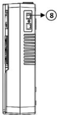
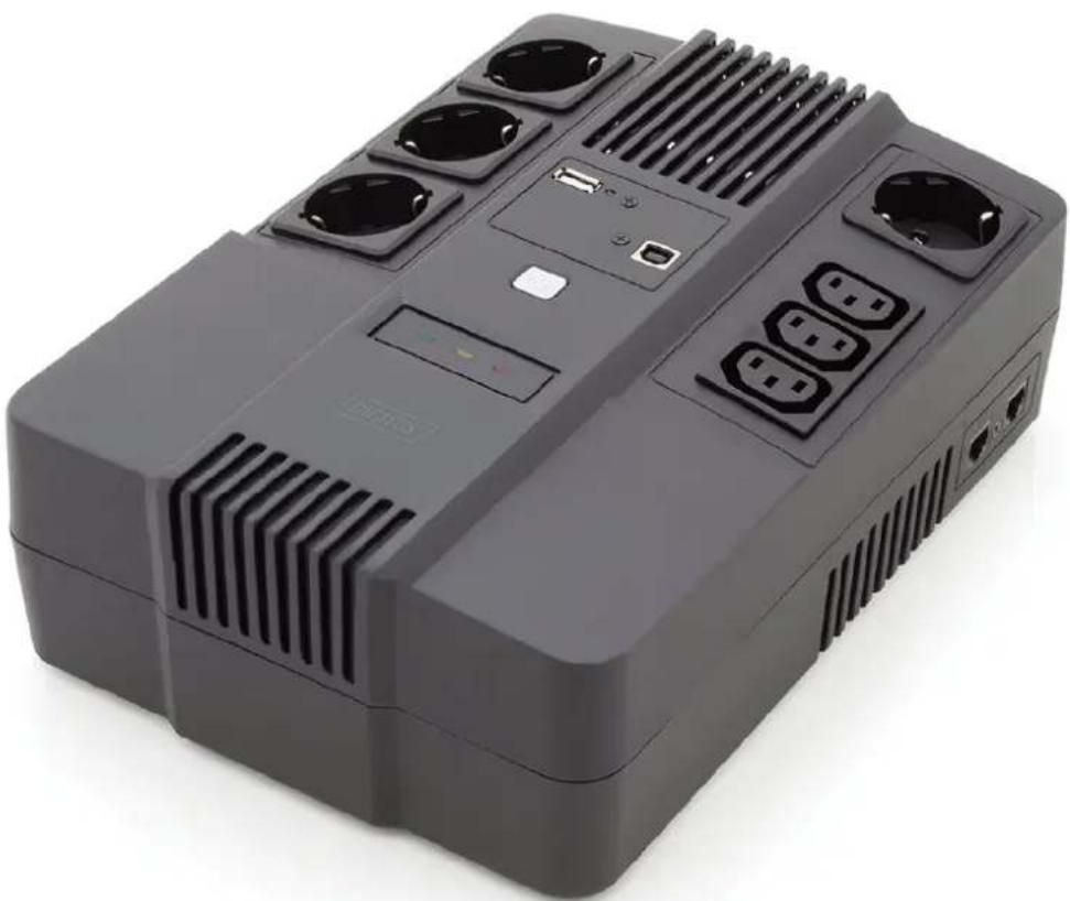
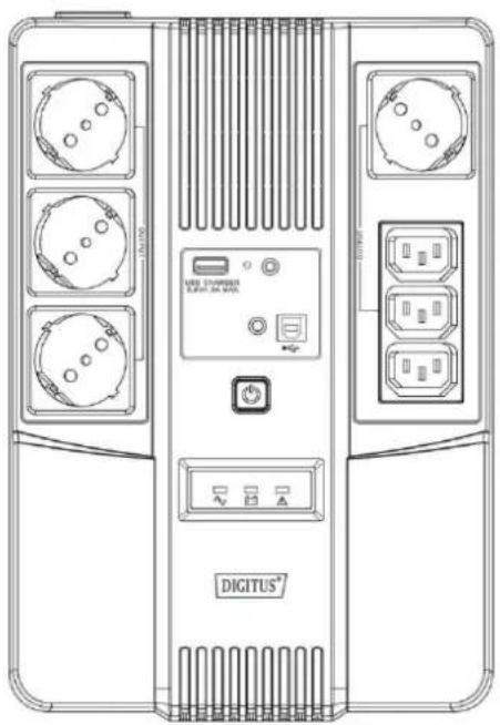
SYSTEM DESCRIPTION
Product Overview:
- Power Switch
- LED indicator
- USB Charger
- USB Port
- Input
- Bypass
- Output
- RJ45 Port
- Mounting Hole
- Battery Cover
natural_image
Technical line drawing of a device rear panel with labeled ports and connectors (no readable text or symbols beyond branding)
natural_image
Diagram of a device rear panel with internal components and a labeled pin (no text or symbols beyond the number 5)
text_image
Diagram of a device rear panel with labeled components and numbered parts (9, 10)
natural_image
Line drawing of a vertical cylindrical device with internal heat exchanger and side panel (no text or symbols)
text_image
⑦ ③ ① ② ⑥ ⑦ ④
natural_image
Line drawing of a rectangular electronic device with ports and a label pointing to the number 8 (no text or symbols on the device itself)LED Indicators:
• AC Mode: Green - LED lighting
• Battery Mode: Yellow - LED flashing
- Fault Mode: Red - LED lighting
1. Inspection
Remove the UPS from its packaging and inspect it for damage that may have occurred during shipping. If any damage is discovered, repack the unit and return it to the place of purchase.
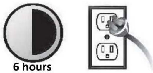
2. Charging
This unit is shipped from the factory with its internal battery fully charged. However, some charge may be lost during shipping and the battery should be recharged prior use. Turn on the UPS, plug the unit into an appropriate power supply and allow the UPS to charge fully by leaving it plugged in for at least 6 hrs with no load (no electrical devices such as computers, monitors, etc.) connected.
text_image
6 hours3. Placement
Install the UPS unit in any protected environment that provides adequate airflow around the unit, and is free from excessive dust, corrosive fumes and conductive contaminants. Do not operate your UPS in an environment where the ambient temperature or humidity is high.

natural_image
Three symbolic icons: a sun with explosion, a smokestack with flame, and an explosion with smoke (no text or labels)On the other hand, place the UPS away from the monitor at least 20cm to avoid interference.
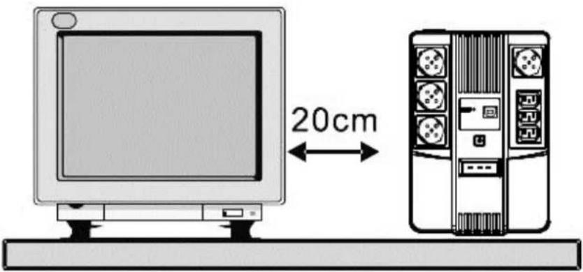
text_image
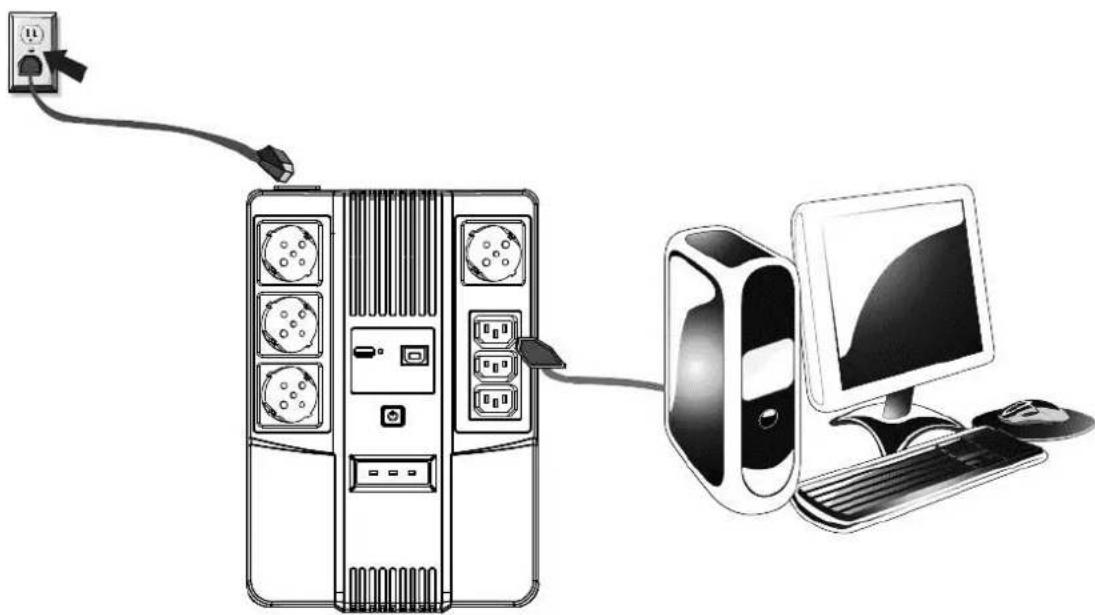
20cm4. Connection
Plug the UPS into a 2-pole, 3-wire grounded receptacle. Then connect one computer-related device into each of the power receptacles supplied on the back of the UPS.
natural_image
Illustration of a desktop computer setup with a server, tower, and monitor connected via cable (no text or symbols)5. Turn On/Off
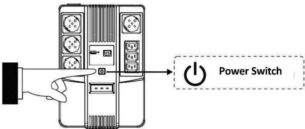
To turn on the UPS unit, press the power switch lightly. To turn off the UPS unit, press the power switch again
text_image
Power Switch6. DC start
All series are equipped with DC Start. To start UPS when AC utility power is not available, simply press the power switch.
TROUBLE SHOOTING
| Symptom Possible Cause Proposed Action | ||
| No LED display on the front panel | 1. Battery weak | 1. Charge battery up to 8 hours |
| 2. Battery defect | 2. Replace with the same type of battery | |
| 3. Power switch is not pressed | 3. Press the power switch again | |
| Alarm buzzer beeps continuously when AC supply is normal | Overload of the UPS | Verify that the load matches the UPS capability specified in the specs |
| When power failure, back-up time is shorten | 1. Overload of the UPS | 1. Remove some non-critical load |
| 2. Battery voltage is too low | 2. Charge battery 8 hours or more | |
| 3. Battery defect | due to high temperature operation environment, or improper operation to battery | 3. Replace with the same type of battery |
| Mains normal but yellow LED is flashing | Power cord is loose Reconnect the power cord properly | |
The manual content may be changed. Please also refer to the latest version on the web shop.
This is a Class A product. In home environment, this product may cause radio interference. In this case, the user may be required to take appropriate measures.
Hereby Assmann Electronic GmbH, declares that the Declaration of Conformity is part of the shipping content. If the Declaration of Conformity is missing, you can request it by post under the below mentioned manufacturer address.
www.assmann.com
Assmann Electronic GmbH
Auf dem Schüffel 3
58513 Lüdenscheid
Germany
text_image
CEDIGITUS®
DIGITUS® All-in-One USV-Anlage

natural_image
Exterior view of a black industrial electronic device with ventilation slots and ports (no visible text or symbols)Benutzerhandbuch
DN-170110 • DN-170111
Sicherheitshinweise
natural_image
Diagram of a device rear panel with internal components and a labeled pin (no text or symbols beyond the number 5)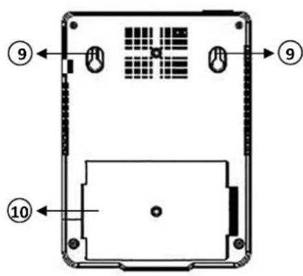
text_image
Diagram of a device rear panel with labeled components and numbered parts (9, 10)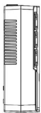
natural_image
Line drawing of a vertical cylindrical device with internal heat exchanger and side panel (no text or symbols)
text_image
⑦ ③ ① ② ⑥ ⑦ ④
natural_image
Line drawing of a vertical electronic device with labeled ports and a numbered arrow pointing to the top-right corner (no text or symbols on the device itself)LED-Anzeigen:
natural_image
Three symbolic icons: a sun with explosion, a smokestack with smoke, and a crossed-out cloud with raindrops (no text or labels)natural_image
Diagram showing a desktop computer connected to a server tower and monitor, with a power outlet and cable (no text or symbols present)natural_image
Black industrial electronic device with multiple power outlets and ventilation slots (no visible text or symbols)natural_image
Diagram of a device rear panel with a highlighted internal component (no text or symbols)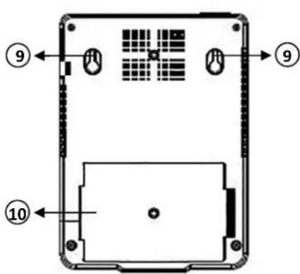
text_image
Diagram of a device rear panel with labeled components and numbered parts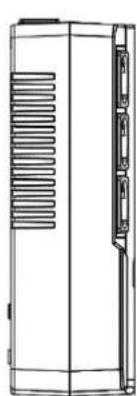
natural_image
Line drawing of a rectangular electronic device with ventilation slots and a side panel (no text or symbols)
text_image
Diagram of a server rack with numbered components and labeled ports, showing internal layout and connections.
natural_image
Line drawing of a rectangular electronic device with ports and a labeled component (no text or symbols beyond the number 8)Voyant LED :
natural_image
Three symbolic icons: a sun with smoke, a factory chimney, and an explosion with raindrops (no text or labels)natural_image
Diagram showing a desktop computer connected to a server tower and monitor, with a power outlet and cable (no text or symbols present)5. Allumer/éteindre
natural_image
Exterior view of a black rectangular electronic device with ventilation slots and ports (no visible text or symbols)Manuale dell'utente
DN-170110 • DN-170111
natural_image
Technical line drawing of a dual-chamber electronic device with labeled ports and connectors (no readable text or symbols beyond branding)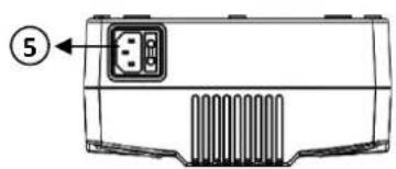
natural_image
Diagram of a device rear panel with internal components and a labeled pin (no text or symbols beyond the number 5)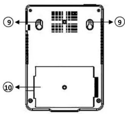
text_image
Diagram of a device rear panel with labeled components and numbered parts (9, 10)
natural_image
Technical line drawing of a vertical cylindrical device with internal heat exchanger and side panel (no text or symbols)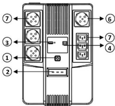
text_image
⑦ ③ ① ② ⑥ ⑦ ④
natural_image
Line drawing of a rectangular electronic device with ports and a labeled section (8), no text or symbols present.Indicatori LED:
natural_image
Three symbolic icons: a sun with explosion, a smokestack with flame, and an explosion with smoke (no text or labels)natural_image
Diagram showing a desktop computer connected to a server tower and monitor, with a power outlet and cable (no text or symbols present)natural_image
Exterior view of a black rectangular electronic device with ventilation slots and ports (no visible text or symbols)Manual de usuario
DN-170110 • DN-170111
natural_image
Diagram of a device rear panel with a labeled component (no text or symbols beyond the number 5)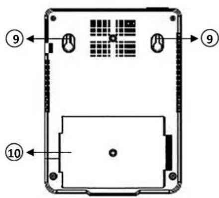
text_image
Diagram of a device rear panel with labeled components and numbered parts
natural_image
Technical line drawing of a vertical cylindrical device with internal heat exchanger and side panel (no text or symbols)
text_image
Diagram of a server rack with numbered ports and labeled connectors
natural_image
Line drawing of a rectangular electronic device with ports and ventilation slots, labeled with number 8 (no text or symbols on the device itself)Indicadores LED:
natural_image
Three symbolic icons: a sun with a lightning bolt, a smokestack with flames, and an explosion with a cross (no text or labels)natural_image
Diagram showing a desktop computer connected to a server tower and monitor, with a power outlet and cable (no text or symbols present)5. Encender/apagar
natural_image
Black industrial electronic device with multiple ports and ventilation slots (no visible text or symbols)natural_image
Diagram of a device rear panel with ports and ventilation slots (no text or symbols)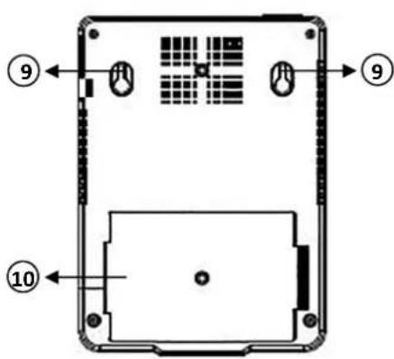
text_image
Diagram of a device rear panel with labeled components and numbered parts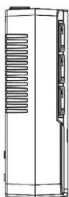
natural_image
Line drawing of a vertical cabinet with ventilation grilles and a side panel (no text or symbols)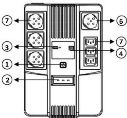
text_image
⑦ ③ ① ② ⑥ ⑦ ④